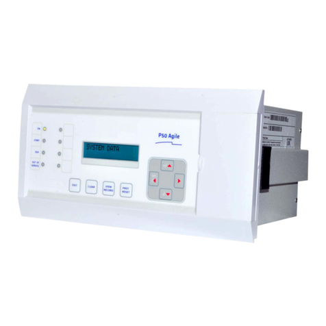
GE D90 Plus Use and care manual

GE
Grid Solutions
Product version: 1.9x
GE publication code: 1601-9070-F4 (GEK-113469D)
D90Plus
Line Distance Protection System
Communications Guide
1601-9070-F4
IISO 9001
G
N
E
I
L
M
I
U
T
L
T
E
S
I
R
G
E
E
D
R

Copyright © 2016 GE Multilin Inc. All rights reserved.
D90Plus Line Distance Protection System Communications Guide for version 1.9x.
D90Plus, EnerVista, EnerVista Launchpad, EnerVista URPlus Setup, FlexLogic, FlexMatrix,
FlexAnalog, Multilin, and GE Multilin are trademarks or registered trademarks of GE Multilin
Inc.
The contents of this manual are the property of GE Multilin Inc. This documentation is
furnished on license and may not be reproduced in whole or in part without the permission
of GE Multilin. The content of this manual is for informational use only and is subject to
change without notice.
Part number: 1601-9070-F4 (October 2016)

D90PLUS LINE DISTANCE PROTECTION SYSTEM – COMMUNICATIONS GUIDE iii
D90Plus Line Distance Protection System
Table of contents
1 INTRODUCTION Safety symbols and definitions....................................................................................1
For further assistance ...................................................................................................1
2MODBUS
COMMUNICATION
Modbus protocol overview ...........................................................................................3
Physical layer....................................................................................................................................................3
Data link layer ..................................................................................................................................................4
CRC-16 algorithm...........................................................................................................................................4
Modbus function codes .................................................................................................5
Read actual values ........................................................................................................................................5
Execute command.........................................................................................................................................6
Exception responses.....................................................................................................................................7
Modbus settings .............................................................................................................8
Modbus protocol.............................................................................................................................................8
Modbus user map ..........................................................................................................................................8
Modbus memory map....................................................................................................9
Modbus data formats............................................................................................................................. 156
3DNP
COMMUNICATION
DNP device profile ..................................................................................................... 197
DNP v3.00 device profile document ................................................................................................ 197
DNP v3.00 implementation document........................................................................................... 199
DNP protocol settings............................................................................................................................. 208
DNP points .................................................................................................................. 212
Binary input points................................................................................................................................... 212
Binary and control relay output points ..........................................................................................212
Binary and frozen counter points ..................................................................................................... 213
Analog input points ................................................................................................................................. 214
DNP user point list settings.................................................................................................................. 214
INDEX

iv D90PLUS LINE DISTANCE PROTECTION SYSTEM – COMMUNICATIONS GUIDE
TABLE OF CONTENTS

D90PLUS LINE DISTANCE PROTECTION SYSTEM – COMMUNICATIONS GUIDE 1
D90Plus Line Distance Protection System
Chapter 1: Introduction
Introduction
This document outlines the communications protocols for the D90Plus Line Distance
Protection System. It is intended for customers who need detailed knowledge of the
D90Plus implementation of the communications protocols, for example to design a client or
to troubleshoot an interoperability issue. Use this guide with the Instruction Manual for the
product.
This chapter outlines safety and technical support information.
Safety symbols and definitions
Before attempting to install or use the device, review all safety indicators in this document
to help prevent injury, equipment damage, or downtime.
The following safety and equipment symbols are used in this document.
DANGER
Indicates a hazardous situation which, if not avoided, will result in death or serious
injury.
WARNING
Indicates a hazardous situation which, if not avoided, could result in death or serious
injury.
CAUTION
Indicates a hazardous situation which, if not avoided, could result in minor or
moderate injury.
NOTICE
Indicates practices not related to personal injury.
For further assistance
For product support, contact the information and call center as follows:
GE Grid Solutions
650 Markland Street
Markham, Ontario
Canada L6C 0M1

2D90
PLUS LINE DISTANCE PROTECTION SYSTEM – COMMUNICATIONS GUIDE
FOR FURTHER ASSISTANCE CHAPTER 1: INTRODUCTION
Worldwide telephone: +1 905 927 7070
Europe/Middle East/Africa telephone: +34 94 485 88 54
North America toll-free: 1 800 547 8629
Fax: +1 905 927 5098
Website: http://www.gegridsolutions.com/multilin

D90PLUS LINE DISTANCE PROTECTION SYSTEM – COMMUNICATIONS GUIDE 3
D90Plus Line Distance Protection System
Chapter 2: Modbus communication
Modbus communication
This chapter outlines the Modbus protocol. Use the memory map at the end of the chapter
when designing a client to access the D90Plus device using Modbus.
Modbus protocol overview
Modbus is a standard protocol for communication among devices. Modbus is available via
serial links (Modbus remote terminal unit, or RTU) or Ethernet (Modbus/TCP). The D90Plus
supports Modbus RTU.
The D90Plus acts as a slave device. It listens and responds to requests issued by a master
computer. It never initiates communications.
The following description is intended for users who want to develop their own
communication drivers and applies to the serial Modbus RTU protocol.
Physical layer
The Modbus RTU protocol is hardware-independent, allowing the physical layer to be any
standard hardware configuration. The D90Plus includes a front USB port and rear
communications ports that can be configured as RS485, 10/100Base-T, or 100Base-F.
Data flow is auto-negotiated to half-duplex or full-duplex in all configurations.
Each data byte is transmitted in an asynchronous format consisting of one start bit, eight
data bits, one stop bit, and possibly one parity bit. This produces a 10 or 11-bit data frame.
This can be important for transmission through modems at high bit rates (11 bit data
frames are not supported by many modems at baud rates greater than 300).
The baud rate and parity are independently programmable for each communications port.
Baud rates of 300, 1200, 2400, 4800, 9600, 14400, 19200, 28800, 33600, 38400, 57600, or
115200 bps are available. Even, odd, and no parity are available.
The master device in any system must know the address of the slave device for
communication. The relay does not act on a request from a master if the address in the
request does not match the relay slave address, unless the address is the broadcast
address.

4D90
PLUS LINE DISTANCE PROTECTION SYSTEM – COMMUNICATIONS GUIDE
MODBUS PROTOCOL OVERVIEW CHAPTER 2: MODBUS COMMUNICATION
Data link layer
Communication takes place in packets that are groups of asynchronously framed byte
data. The master transmits a packet to the slave and the slave responds with a packet. The
end of a packet is marked by dead-time on the communications line. The table shows the
general format for both transmit and receive packets.
Table 1: Modbus packet format
The slave address indicates the address of the slave device intended to receive the packet
sent by the master and to perform the required action. Each slave device on a
communications bus must have a unique address to prevent bus contention. The D90Plus
slave address is programmable from 1 to 254. Only the slave addressed responds to a
packet that starts with its address. Note that the faceplate USB port is an exception to this
rule; it acts on a message containing any slave address.
A master transmit packet with slave address 0 indicates a broadcast command. All slaves
on the communication link take action based on the packet, but none respond to the
master. Broadcast mode is only recognized when associated with function code 05h. For
any other function code, a packet with broadcast mode slave address 0 is ignored.
The function code tells the slave which action to perform. An exception response from the
slave is indicated by setting the high order bit of the function code in the response packet.
The data format is a variable number of bytes depending on the function code. This can
include actual values or addresses sent by the master to the slave or by the slave to the
master.
The CRC is a two-byte error checking code. Modbus RTU includes a 16-bit cyclic
redundancy check (CRC-16) with every packet. This is an industry standard method used
for error detection. If a Modbus slave device receives a packet in which an error is
indicated by the CRC, the slave device does not act upon or respond to the packet. This
prevents erroneous operations.
A packet is terminated when no data is received for a period of 3.5 byte transmission times
(about 15 ms at 2400 bps, 2 ms at 19200 bps, and 300 µs at 115200 bps). Consequently,
the transmitting device must not allow gaps between bytes longer than this interval. Once
the dead time has expired without a new byte transmission, all slaves start listening for a
new packet from the master except for the addressed slave.
CRC-16 algorithm
The 16-bit cyclic redundancy check (CRC-16) algorithm treats the entire data stream (data
bits only; start, stop, and parity ignored) as one continuous binary number. This number is
shifted left 16 bits and then divided by a characteristic polynomial (11000000000000101B).
The 16-bit remainder of the division is appended to the end of the packet, MSByte first. The
resulting packet including CRC, when divided by the same polynomial at the receiver, gives
a zero remainder if no transmission errors have occurred. This algorithm requires the
characteristic polynomial to be reverse-bit ordered. The most significant bit of the
characteristic polynomial is dropped, since it does not affect the value of the remainder.
A C programming language implementation of the CRC algorithm is provided upon
request. The algorithm is as follows:
Description Size
Slave address 1 byte
Function code 1 byte
Data 1 or more bytes
CRC 2 bytes
Dead time 3.5 bytes transmission time

CHAPTER 2: MODBUS COMMUNICATION MODBUS FUNCTION CODES
D90PLUS LINE DISTANCE PROTECTION SYSTEM – COMMUNICATIONS GUIDE 5
1. FFFF (hex) --> A
2. 0 --> i
3. 0 --> j
4. Di (+) Alow --> Alow
5. j + 1 --> j
6. shr (A)
7. Is there a carry?
If No: go to 8;
If Yes: G (+) A --> A and continue
8. Is j = 8?
If No: go to 5;
If Yes: continue
9. i + 1 --> i
10.Is i = N?
If No: go to 3;
If Yes: continue
11. A --> CRC
where
--> is data transfer
Ais 16-bit working register
Alow is low order byte of A
Ahigh is high order byte of A
CRC is 16-bit CRC-16 result
i, jare loop counters
(+) is logical exclusive-OR operator
Nis total number of data bytes
Di is the i-th data byte (i= 0 to N–1)
Gis 16-bit characteristic polynomial = 1010000000000001 (binary) with MSbit dropped and
bit order reversed
shr (x) is right-shift operator (the LSbit of xis shifted into a carry flag, a "0" is shifted into
the MSbit of x, all other bits are shifted right one location)
Modbus function codes
While the Modbus protocol defines function codes from 1 to 127, only a small subset
generally is needed. The table outlines the functions supported by the D90Plus.
Table 2: Modbus function codes supported
Read actual values
The read actual values function codes (04h) allow the master to read one or more
consecutive data registers (actual values) from a D90Plus device. Data registers are always
16-bit (two-byte) values transmitted with the high-order byte first. The maximum number
of registers that can be read in a single packet is 125. See the Modbus Memory Map table
for details on the data registers.
Function code Modbus definition GE Grid Solutions definition
Hex Decimal
03 3 Read holding registers Read settings
04 4 Read input registers Read actual values
05 5 Force single coil Execute command

6D90
PLUS LINE DISTANCE PROTECTION SYSTEM – COMMUNICATIONS GUIDE
MODBUS FUNCTION CODES CHAPTER 2: MODBUS COMMUNICATION
The following tables show the format of the master and slave packets. The example shows
a master device requesting three register values starting at address 4050h from slave
device 11h (17 decimal); the slave device responds with the values 40, 300, and 0 from
registers 4050h, 4051h, and 4052h, respectively.
Table 3: Master transmission packet example, function code 04h
Table 4: Slave response packet example, function code 04h
Execute command
The execute command function allows the master to perform operations in the relay. The
following table outlines the operations available.
Table 5: Summary of operation codes for function 05h
The following tables illustrate the format of the master and slave packets for function code
05h. The example shows a master device requesting the slave device 11h (17 decimal) to
perform a reset. The high and low code value bytes always have the values “FF” and “00”
respectively and are a remnant of the original Modbus definition of this function code.
Packet format Example (hex)
Slave address 11
Function code 04
Data starting address - high order byte 40
Data starting address - low order byte 50
Number of registers - high order byte 00
Number of registers - low order byte 03
CRC - low order byte A7
CRC - high order byte 4A
Packet format Example (hex)
Slave address 11
Function code 04
Byte count 06
Data byte 1 - high order byte 00
Data byte 1 - low order byte 28
Data byte 2 - high order byte 01
Data byte 2 - low order byte 2C
Data byte 3 - high order byte 00
Data byte 3 - low order byte 00
CRC - low order byte 0D
CRC - high order byte 60
Operation code Definition Description
0000h NO OPERATION Does not do anything
0001h RESET Performs the same function as the Reset command
0005h CLEAR EVENT RECORDS Performs the same function as the Clear Event
Records command
0006h CLEAR OSCILLOGRAPHY Clears all oscillography records
1000h to 103Fh VIRTUAL IN 1 to 64 ON/OFF Sets the states of virtual inputs 1 to 64 either “ON”
or “OFF”

CHAPTER 2: MODBUS COMMUNICATION MODBUS FUNCTION CODES
D90PLUS LINE DISTANCE PROTECTION SYSTEM – COMMUNICATIONS GUIDE 7
Table 6: Master transmission packet example, function code 05h
Table 7: Slave response packet example, function code 05h
Exception responses
Operation errors usually occur because of illegal data in a packet. These errors result in an
exception response from the slave. The slave detecting one of these errors sends a
response packet to the master with the high order bit of the function code set to 1.
The following tables illustrate the format of the master and slave packets for an exception
response. The example shows a master device sending the unsupported function code
39h to slave device 11.
Table 8: Exception response packet example, transmission
Table 9: Exception response packet example, reception
Packet format Example (hex)
Slave address 11
Function code 05
Operation code - high order byte 00
Operation code - low order byte 01
Code value - high order byte FF
Code value - low order byte 00
CRC - low order byte DF
CRC - high order byte 6A
Packet format Example (hex)
Slave address 11
Function code 05
Operation code - high order byte 00
Operation code - low order byte 01
Code value - high order byte FF
Code value - low order byte 00
CRC - low order byte DF
CRC - high order byte 6A
Packet format Example (hex)
Slave address 11
Function code 39
CRC - low order byte CD
CRC - high order byte F2
Packet format Example (hex)
Slave address 11
Function code B9
Error code 01
CRC - low order byte 93
CRC - high order byte 95

8D90
PLUS LINE DISTANCE PROTECTION SYSTEM – COMMUNICATIONS GUIDE
MODBUS SETTINGS CHAPTER 2: MODBUS COMMUNICATION
Modbus settings
This section outlines configuration settings from the instruction manual.
Modbus protocol
The Modbus server can simultaneously support one client over serial RS485 and four
clients over Ethernet. The server is capable of reporting any indication or measurement
and operating any output present in the device. A user-configurable input and output map
also is implemented.
The D90Plus operates as a Modbus slave device only.
In the EnerVista software, select the Settings > Communications > Modbus > Protocol
menu to open the Modbus protocol configuration window.
Figure 1: Modbus protocol configuration settings
The following settings are available.
Modbus Slave Address
Range: 1 to 254 in steps of 1
Default: 254
This setting specifies the Modbus slave address for the D90Plus. Each device must have a
unique address from 1 to 254. Address 0 and addresses from 248 and up are reserved by
the Modbus protocol specification, and so their use here is not recommended. Address 0
is the broadcast address to which all Modbus slave devices listen. Addresses do not have
to be sequential, but no two devices can have the same address or conflicts resulting in
errors occur. Generally, starting at 1, set each device added to the link to the next higher
address.
Modbus TCP Port Number
Range: 1 to 65535 in steps of 1
Default: 502
Modbus over TCP/IP can also be used on any of the Ethernet ports. This setting specifies
the Modbus TCP port number for Ethernet communications. Power to the D90Plus must
be cycled for changes to this setting to take effect.
NOTE
Do not set more than one protocol to the same TCP/UDP port number, as this results in
unreliable operation of those protocols.
Modbus user map
The Modbus user map provides read-only access for up to 256 registers. To obtain a
memory map value, enter the address in the Parameter field (this value must be converted
from hexadecimal to decimal format). The corresponding value (if programmed) displays in
the Value field. A value of “0” in subsequent register Address lines automatically returns

CHAPTER 2: MODBUS COMMUNICATION MODBUS MEMORY MAP
D90PLUS LINE DISTANCE PROTECTION SYSTEM – COMMUNICATIONS GUIDE 9
values for the previous Address lines incremented by 1. An address value of “0” in the initial
register means "none" and values of “0” displays for all registers. Different address values
can be entered as required in any of the register positions.
Select the Settings > Communications > Modbus > User Map menu to open the Modbus
user map configuration window.
Figure 2: Modbus user map configuration settings
The following settings are available for each of the 256 registers.
Modbus Type
Range: None, Settings, Actuals
Default: None
This setting indicates if the Modbus user map address represents a setting or an actual
value.
Parameter
Range: Modbus memory map address in decimal representation
Default: 0
This setting represents the value of the programmed Modbus memory map address.
Modbus memory map
The table outlines the user-accessible features of the D90Plus Modbus memory map. Those
present depend on order code.
The memory map is also viewable in a web browser. In the browser, enter the IP address of
the D90Plus.
The memory map is also provided as a .ini file. See the SYS_ModbusMemoryMap.ini file
provided on the CD.
See the Modbus data formats section that follows for details on the Format codes for each
register, for example F001.

10 D90PLUS LINE DISTANCE PROTECTION SYSTEM – COMMUNICATIONS GUIDE
MODBUS MEMORY MAP CHAPTER 2: MODBUS COMMUNICATION
Table 10: Modbus memory map
Address Description Range Units Step Format Default
Product Information (Read Only)
0000 UR Product Type 0 to 65535 --- 1 F001 0
0002 Product Version 0 to 655.35 --- 0.01 F001 110
Product Information (Read Only - Written by Factory)
0010 Serial Number --- --- --- F203 “0”
0020 Manufacturing Date 0 to 4294967295 --- 1 F050 0
0022 Modification Number 0 to 65535 --- 1 F001 0
Product Information (Read Only Non-Volatile)
0023 Operating Time 0 to 4294967295 --- 1 F050 0
Product Information (Read Only - Written by Factory)
0040 Order Code --- --- --- F204 “Order Code
x”
0090 Ethernet MAC Address --- --- --- F072 0
0093 Reserved (13 items) --- --- --- F001 0
Communications Actual Values (Read Only)
0128 Modbus Available TCP/IP Connections 0 to 65535 --- --- F001 0
0129 MMS Available TCP/IP Connections 0 to 65535 --- --- F001 0
012A PMU Available TCP/IP Connections 0 to 65535 --- --- F001 0
012B IEC Available TCP/IP Connections 0 to 65535 --- --- F001 0
012C DNP Available TCP/IP Connections 0 to 65535 --- --- F001 0
0130 Port 1 Ethernet Actual Mode 0 to 2 --- 1 F192 0 (10/100
BASE-TX)
0131 Port 1 Ethernet Duplex 0 to 1 --- 1 F171 0 (Half
Duplex)
0132 Port 1 Ethernet Speed 0 to 1 --- 1 F170 0 (10 Mps)
0133 Port 1 Ethernet Link Status 0 to 1 --- 1 F155 0 (Offline)
0134 Port 2 Ethernet Actual Mode 0 to 2 --- 1 F192 0 (10/100
BASE-TX)
0135 Port 2 Ethernet Duplex 0 to 1 --- 1 F171 0 (Half
Duplex)
0136 Port 2 Ethernet Speed 0 to 1 --- 1 F170 0 (10 Mps)
0137 Port 2 Ethernet Link Status 0 to 1 --- 1 F155 0 (Offline)
0138 Port 3 Ethernet Actual Mode 0 to 2 --- 1 F192 0 (10/100
BASE-TX)
0139 Port 3 Ethernet Duplex 0 to 1 --- 1 F171 0 (Half
Duplex)
013A Port 3 Ethernet Speed 0 to 1 --- 1 F170 0 (10 Mps)
013B Port 3 Ethernet Link Status 0 to 1 --- 1 F155 0 (Offline)
013C Configure IP Network Status 0 to 19 --- 1 F173 0 (OK)
013D Active Port 1 IP Address 0 to 4294967295 --- 1 F003 0
013F Active Port 1 IP Subnet Mask 0 to 4294967295 --- 1 F003 0
0141 Active Port 1 Gateway IP Address 0 to 4294967295 --- 1 F003 0
0143 Active Port 2 IP Address 0 to 4294967295 --- 1 F003 0
0145 Active Port 2 IP Subnet Mask 0 to 4294967295 --- 1 F003 0
0147 Active Port 2 Gateway IP Address 0 to 4294967295 --- 1 F003 0
0149 Active Port 3 IP Address 0 to 4294967295 --- 1 F003 0
014B Active Port 3 IP Subnet Mask 0 to 4294967295 --- 1 F003 0
014D Active Port 3 Gateway IP Address 0 to 4294967295 --- 1 F003 0

CHAPTER 2: MODBUS COMMUNICATION MODBUS MEMORY MAP
D90PLUS LINE DISTANCE PROTECTION SYSTEM – COMMUNICATIONS GUIDE 11
014F IEC Protocol Function 0 to 1 --- 1 F126 0 (No)
0150 IEC 61850 Available 0 to 1 --- 1 F126 0 (No)
Settings Notification (Read/Write)
0150 Settings Notification Function 0 to 3 --- 1 F010 3 (N_IDLE)
Settings Notification Actual Values (Read Only)
0151 Settings Notification in Progress 0 to 3 --- 1 F010 0 (N_Clear)
0152 Settings Notification Status 0 to 2 --- 1 F134 0 (N/A)
0153 Settings Notification Load Diagram 0 to 1 --- 1 F102 0 (Disabled)
Settings Notification Commands (Read/Write Command)
0154 Settings Notification Diagram Acknowledge 0 to 2 1 F134 0 (N/A)
Virtual Input Commands (Read/Write Commands) (64 Modules)
0400 Virtual Input 1 Command 0 to 1 --- 1 F108 0 (Off)
0401 Virtual Input 2 Command 0 to 1 --- 1 F108 0 (Off)
0402 Virtual Input 3 Commands 0 to 1 --- 1 F108 0 (Off)
0403 Virtual Input 4 Commands 0 to 1 --- 1 F108 0 (Off)
0404 Virtual Input 5 Commands 0 to 1 --- 1 F108 0 (Off)
0405 Virtual Input 6 Commands 0 to 1 --- 1 F108 0 (Off)
0406 Virtual Input 7 Commands 0 to 1 --- 1 F108 0 (Off)
0407 Virtual Input 8 Commands 0 to 1 --- 1 F108 0 (Off)
0408 Virtual Input 9 Commands 0 to 1 --- 1 F108 0 (Off)
0409 Virtual Input 10 Commands 0 to 1 --- 1 F108 0 (Off)
040A Virtual Input 11 Commands 0 to 1 --- 1 F108 0 (Off)
040B Virtual Input 12 Commands 0 to 1 --- 1 F108 0 (Off)
040C Virtual Input 13 Commands 0 to 1 --- 1 F108 0 (Off)
040D Virtual Input 14 Commands 0 to 1 --- 1 F108 0 (Off)
040E Virtual Input 15 Commands 0 to 1 --- 1 F108 0 (Off)
040F Virtual Input 16 Commands 0 to 1 --- 1 F108 0 (Off)
0410 Virtual Input 17 Commands 0 to 1 --- 1 F108 0 (Off)
0411 Virtual Input 18 Commands 0 to 1 --- 1 F108 0 (Off)
0412 Virtual Input 19 Commands 0 to 1 --- 1 F108 0 (Off)
0413 Virtual Input 20 Commands 0 to 1 --- 1 F108 0 (Off)
0414 Virtual Input 21 Commands 0 to 1 --- 1 F108 0 (Off)
0415 Virtual Input 22 Commands 0 to 1 --- 1 F108 0 (Off)
0416 Virtual Input 23 Commands 0 to 1 --- 1 F108 0 (Off)
0417 Virtual Input 24 Commands 0 to 1 --- 1 F108 0 (Off)
0418 Virtual Input 25 Commands 0 to 1 --- 1 F108 0 (Off)
0419 Virtual Input 26 Commands 0 to 1 --- 1 F108 0 (Off)
041A Virtual Input 27 Commands 0 to 1 --- 1 F108 0 (Off)
041B Virtual Input 28 Commands 0 to 1 --- 1 F108 0 (Off)
041C Virtual Input 29 Commands 0 to 1 --- 1 F108 0 (Off)
041D Virtual Input 30 Commands 0 to 1 --- 1 F108 0 (Off)
041E Virtual Input 31 Commands 0 to 1 --- 1 F108 0 (Off)
041F Virtual Input 32 Commands 0 to 1 --- 1 F108 0 (Off)
0420 Virtual Input 33 Commands 0 to 1 --- 1 F108 0 (Off)
0421 Virtual Input 34 Commands 0 to 1 --- 1 F108 0 (Off)
0422 Virtual Input 35 Commands 0 to 1 --- 1 F108 0 (Off)
0423 Virtual Input 36 Commands 0 to 1 --- 1 F108 0 (Off)
Address Description Range Units Step Format Default

12 D90PLUS LINE DISTANCE PROTECTION SYSTEM – COMMUNICATIONS GUIDE
MODBUS MEMORY MAP CHAPTER 2: MODBUS COMMUNICATION
0424 Virtual Input 37 Commands 0 to 1 --- 1 F108 0 (Off)
0425 Virtual Input 38 Commands 0 to 1 --- 1 F108 0 (Off)
0426 Virtual Input 39 Commands 0 to 1 --- 1 F108 0 (Off)
0427 Virtual Input 40 Commands 0 to 1 --- 1 F108 0 (Off)
0428 Virtual Input 41 Commands 0 to 1 --- 1 F108 0 (Off)
0429 Virtual Input 42 Commands 0 to 1 --- 1 F108 0 (Off)
042A Virtual Input 43 Commands 0 to 1 --- 1 F108 0 (Off)
042B Virtual Input 44 Commands 0 to 1 --- 1 F108 0 (Off)
042C Virtual Input 45 Commands 0 to 1 --- 1 F108 0 (Off)
042D Virtual Input 46 Commands 0 to 1 --- 1 F108 0 (Off)
042E Virtual Input 47 Commands 0 to 1 --- 1 F108 0 (Off)
042F Virtual Input 48 Commands 0 to 1 --- 1 F108 0 (Off)
0430 Virtual Input 49 Commands 0 to 1 --- 1 F108 0 (Off)
0431 Virtual Input 50 Commands 0 to 1 --- 1 F108 0 (Off)
0432 Virtual Input 51 Commands 0 to 1 --- 1 F108 0 (Off)
0433 Virtual Input 52 Commands 0 to 1 --- 1 F108 0 (Off)
0434 Virtual Input 53 Commands 0 to 1 --- 1 F108 0 (Off)
0435 Virtual Input 54 Commands 0 to 1 --- 1 F108 0 (Off)
0436 Virtual Input 55 Commands 0 to 1 --- 1 F108 0 (Off)
0437 Virtual Input 56 Commands 0 to 1 --- 1 F108 0 (Off)
0438 Virtual Input 57 Commands 0 to 1 --- 1 F108 0 (Off)
0439 Virtual Input 58 Commands 0 to 1 --- 1 F108 0 (Off)
043A Virtual Input 59 Commands 0 to 1 --- 1 F108 0 (Off)
043B Virtual Input 60 Commands 0 to 1 --- 1 F108 0 (Off)
043C Virtual Input 61 Commands 0 to 1 --- 1 F108 0 (Off)
043D Virtual Input 62 Commands 0 to 1 --- 1 F108 0 (Off)
043E Virtual Input 63 Commands 0 to 1 --- 1 F108 0 (Off)
043F Virtual Input 64 Commands 0 to 1 --- 1 F108 0 (Off)
Breaker Actual Values (Read Only) (6 Modules)
06B0 Breaker 1 SCADA AddCause 0 to 65535 --- 1 F500 0
06B1 Breaker 1 HMI AddCause 0 to 65535 --- 1 F500 0
06B8 ...Repeated for Breaker 2
06C0 ...Repeated for Breaker 3
06C8 ...Repeated for Breaker 4
06D0 ...Repeated for Breaker 5
06D8 ...Repeated for Breaker 6
Breaker Actual Values (Read Only Non-Volatile States) (6 Modules)
06B2 Breaker 1 Operations A 0 to 4294967295 --- 1 F003 0
06B4 Breaker 1 Operations B 0 to 4294967295 --- 1 F003 0
06B6 Breaker 1 Operations C 0 to 4294967295 --- 1 F003 0
06BA Breaker 2 Operations A 0 to 4294967295 --- 1 F003 0
06BC Breaker 2 Operations B 0 to 4294967295 --- 1 F003 0
06BE Breaker 2 Operations C 0 to 4294967295 --- 1 F003 0
06C2 Breaker 3 Operations A 0 to 4294967295 --- 1 F003 0
06C4 Breaker 3 Operations B 0 to 4294967295 --- 1 F003 0
06C6 Breaker 3 Operations C 0 to 4294967295 --- 1 F003 0
06CA Breaker 4 Operations A 0 to 4294967295 --- 1 F003 0
Address Description Range Units Step Format Default

CHAPTER 2: MODBUS COMMUNICATION MODBUS MEMORY MAP
D90PLUS LINE DISTANCE PROTECTION SYSTEM – COMMUNICATIONS GUIDE 13
06CC Breaker 4 Operations B 0 to 4294967295 --- 1 F003 0
06CE Breaker 4 Operations C 0 to 4294967295 --- 1 F003 0
06D2 Breaker 5 Operations A 0 to 4294967295 --- 1 F003 0
06D4 Breaker 5 Operations B 0 to 4294967295 --- 1 F003 0
06D6 Breaker 5 Operations C 0 to 4294967295 --- 1 F003 0
06DA Breaker 6 Operations A 0 to 4294967295 --- 1 F003 0
06DC Breaker 6 Operations B 0 to 4294967295 --- 1 F003 0
06DE Breaker 6 Operations C 0 to 4294967295 --- 1 F003 0
Breaker Commands (Read/Write Command) (6 Modules)
06E0 Breaker 1 SCADA Command 0 to 15 --- 1 F107 0 (None)
06E1 Breaker 1 HMI Command 0 to 15 --- 1 F107 0 (None)
06E2 ...Repeated for Breaker 2
06E4 ...Repeated for Breaker 3
06E6 ...Repeated for Breaker 4
06E8 ...Repeated for Breaker 5
06EA ...Repeated for Breaker 6
Disconnect Actual Values (Read Only) (30 Modules)
06F0 Disconnect 1 SCADA AddCause 0 to 65535 --- 1 F500 0
06F1 Disconnect 1 HMI AddCause 0 to 65535 --- 1 F500 0
06F4 ...Repeated for Disconnect 2
06F8 ...Repeated for Disconnect 3
06FC ...Repeated for Disconnect 4
0700 ...Repeated for Disconnect 5
0704 ...Repeated for Disconnect 6
0708 ...Repeated for Disconnect 7
070C ...Repeated for Disconnect 8
0710 ...Repeated for Disconnect 9
0714 ...Repeated for Disconnect 10
0718 ...Repeated for Disconnect 11
071C ...Repeated for Disconnect 12
0720 ...Repeated for Disconnect 13
0724 ...Repeated for Disconnect 14
0728 ...Repeated for Disconnect 15
072C ...Repeated for Disconnect 16
0730 ...Repeated for Disconnect 17
0734 ...Repeated for Disconnect 18
0738 ...Repeated for Disconnect 19
073C ...Repeated for Disconnect 20
0740 ...Repeated for Disconnect 21
0744 ...Repeated for Disconnect 22
0748 ...Repeated for Disconnect 23
074C ...Repeated for Disconnect 24
0750 ...Repeated for Disconnect 25
0754 ...Repeated for Disconnect 26
0758 ...Repeated for Disconnect 27
075C ...Repeated for Disconnect 28
0760 ...Repeated for Disconnect 29
Address Description Range Units Step Format Default

14 D90PLUS LINE DISTANCE PROTECTION SYSTEM – COMMUNICATIONS GUIDE
MODBUS MEMORY MAP CHAPTER 2: MODBUS COMMUNICATION
0764 ...Repeated for Disconnect 30
Disconnect Operations Actual Values (Read Only Non-Volatile States) (30 Modules)
06F2 Disconnect 1 Operations 0 to 4294967295 --- 1 F003 0
06F6 Disconnect 2 Operations 0 to 4294967295 --- 1 F003 0
06FA Disconnect 3 Operations 0 to 4294967295 --- 1 F003 0
06FE Disconnect 4 Operations 0 to 4294967295 --- 1 F003 0
0702 Disconnect 5 Operations 0 to 4294967295 --- 1 F003 0
0706 Disconnect 6 Operations 0 to 4294967295 --- 1 F003 0
070A Disconnect 7 Operations 0 to 4294967295 --- 1 F003 0
070E Disconnect 8 Operations 0 to 4294967295 --- 1 F003 0
0712 Disconnect 9 Operations 0 to 4294967295 --- 1 F003 0
0716 Disconnect 10 Operations 0 to 4294967295 --- 1 F003 0
071A Disconnect 11 Operations 0 to 4294967295 --- 1 F003 0
071E Disconnect 12 Operations 0 to 4294967295 --- 1 F003 0
0722 Disconnect 13 Operations 0 to 4294967295 --- 1 F003 0
0726 Disconnect 14 Operations 0 to 4294967295 --- 1 F003 0
072A Disconnect 15 Operations 0 to 4294967295 --- 1 F003 0
072E Disconnect 16 Operations 0 to 4294967295 --- 1 F003 0
0732 Disconnect 17 Operations 0 to 4294967295 --- 1 F003 0
0736 Disconnect 18 Operations 0 to 4294967295 --- 1 F003 0
073A Disconnect 19 Operations 0 to 4294967295 --- 1 F003 0
073E Disconnect 20 Operations 0 to 4294967295 --- 1 F003 0
0742 Disconnect 21 Operations 0 to 4294967295 --- 1 F003 0
0746 Disconnect 22 Operations 0 to 4294967295 --- 1 F003 0
074A Disconnect 23 Operations 0 to 4294967295 --- 1 F003 0
074E Disconnect 24 Operations 0 to 4294967295 --- 1 F003 0
0752 Disconnect 25 Operations 0 to 4294967295 --- 1 F003 0
0756 Disconnect 26 Operations 0 to 4294967295 --- 1 F003 0
075A Disconnect 27 Operations 0 to 4294967295 --- 1 F003 0
075E Disconnect 28 Operations 0 to 4294967295 --- 1 F003 0
0762 Disconnect 29 Operations 0 to 4294967295 --- 1 F003 0
0766 Disconnect 30 Operations 0 to 4294967295 --- 1 F003 0
Disconnect SCADA Commands (Read/Write Commands) (30 Modules)
0770 Disconnect 1 SCADA Command 0 to 15 --- 1 F107 0 (None)
0771 Disconnect 1 HMI Command 0 to 15 --- 1 F107 0 (None)
0772 ...Repeated for Disconnect 2
0774 ...Repeated for Disconnect 3
0776 ...Repeated for Disconnect 4
0778 ...Repeated for Disconnect 5
077A ...Repeated for Disconnect 6
077C ...Repeated for Disconnect 7
077E ...Repeated for Disconnect 8
0780 ...Repeated for Disconnect 9
0782 ...Repeated for Disconnect 10
0784 ...Repeated for Disconnect 11
0786 ...Repeated for Disconnect 12
0788 ...Repeated for Disconnect 13
Address Description Range Units Step Format Default

CHAPTER 2: MODBUS COMMUNICATION MODBUS MEMORY MAP
D90PLUS LINE DISTANCE PROTECTION SYSTEM – COMMUNICATIONS GUIDE 15
078A ...Repeated for Disconnect 14 0 to 15 --- 1 F107 0 (None)
078C ...Repeated for Disconnect 15 0 to 15 --- 1 F107 0 (None)
078E ...Repeated for Disconnect 16 0 to 15 --- 1 F107 0 (None)
0790 ...Repeated for Disconnect 17 0 to 15 --- 1 F107 0 (None)
0792 ...Repeated for Disconnect 18 0 to 15 --- 1 F107 0 (None)
0794 ...Repeated for Disconnect 19 0 to 15 --- 1 F107 0 (None)
0796 ...Repeated for Disconnect 20 0 to 15 --- 1 F107 0 (None)
Disconnect SCADA commands (read/write commands, 30 modules)
0770 Disconnect 1 SCADA command 0 to 15 --- 1 F107 0 (None)
0772 Disconnect 2 SCADA command 0 to 15 --- 1 F107 0 (None)
0774 Disconnect 3 SCADA command 0 to 15 --- 1 F107 0 (None)
0776 Disconnect 4 SCADA command 0 to 15 --- 1 F107 0 (None)
0778 Disconnect 5 SCADA command 0 to 15 --- 1 F107 0 (None)
077A Disconnect 6 SCADA command 0 to 15 --- 1 F107 0 (None)
077C Disconnect 7 SCADA command 0 to 15 --- 1 F107 0 (None)
077E Disconnect 8 SCADA command 0 to 15 --- 1 F107 0 (None)
0780 Disconnect 9 SCADA command 0 to 15 --- 1 F107 0 (None)
0782 Disconnect 10 SCADA command 0 to 15 --- 1 F107 0 (None)
0784 Disconnect 11 SCADA command 0 to 15 --- 1 F107 0 (None)
0786 Disconnect 12 SCADA command 0 to 15 --- 1 F107 0 (None)
0788 Disconnect 13 SCADA command 0 to 15 --- 1 F107 0 (None)
078A Disconnect 14 SCADA command 0 to 15 --- 1 F107 0 (None)
078C Disconnect 15 SCADA command 0 to 15 --- 1 F107 0 (None)
078E Disconnect 16 SCADA command 0 to 15 --- 1 F107 0 (None)
0790 Disconnect 17 SCADA command 0 to 15 --- 1 F107 0 (None)
0792 Disconnect 18 SCADA command 0 to 15 --- 1 F107 0 (None)
0794 Disconnect 19 SCADA command 0 to 15 --- 1 F107 0 (None)
0796 Disconnect 20 SCADA command 0 to 15 --- 1 F107 0 (None)
0798 Disconnect 21 SCADA command 0 to 15 --- 1 F107 0 (None)
079A Disconnect 22 SCADA command 0 to 15 --- 1 F107 0 (None)
079C Disconnect 23 SCADA command 0 to 15 --- 1 F107 0 (None)
079E Disconnect 24 SCADA command 0 to 15 --- 1 F107 0 (None)
07A0 Disconnect 25 SCADA command 0 to 15 --- 1 F107 0 (None)
07A2 Disconnect 26 SCADA command 0 to 15 --- 1 F107 0 (None)
07A4 Disconnect 27 SCADA command 0 to 15 --- 1 F107 0 (None)
07A6 Disconnect 28 SCADA command 0 to 15 --- 1 F107 0 (None)
07A8 Disconnect 29 SCADA command 0 to 15 --- 1 F107 0 (None)
07AA Disconnect 30 SCADA command 0 to 15 --- 1 F107 0 (None)
0798 ...Repeated for Disconnect 21 0 to 15 --- 1 F107 0 (None)
079A ...Repeated for Disconnect 22 0 to 15 --- 1 F107 0 (None)
079C ...Repeated for Disconnect 23 0 to 15 --- 1 F107 0 (None)
079E ...Repeated for Disconnect 24 0 to 15 --- 1 F107 0 (None)
07A0 ...Repeated for Disconnect 25 0 to 15 --- 1 F107 0 (None)
07A2 ...Repeated for Disconnect 26 0 to 15 --- 1 F107 0 (None)
07A4 ...Repeated for Disconnect 27 0 to 15 --- 1 F107 0 (None)
07A6 ...Repeated for Disconnect 28 0 to 15 --- 1 F107 0 (None)
07A8 ...Repeated for Disconnect 29 0 to 15 --- 1 F107 0 (None)
Address Description Range Units Step Format Default

16 D90PLUS LINE DISTANCE PROTECTION SYSTEM – COMMUNICATIONS GUIDE
MODBUS MEMORY MAP CHAPTER 2: MODBUS COMMUNICATION
07AA ...Repeated for Disconnect 30 0 to 15 --- 1 F107 0 (None)
Inter Relay Transceiver Actual Values (Read Only) (4 Modules)
07B0 Channel 1 Transmit Bias Current 0 to 65535 µA 1 F001 0
07B1 Channel 1 Transmit Power Level -3276.8 to 3276.7 Dbm 0.1 F002 0
07B2 Channel 1 Receive Power Level -3276.8 to 3276.7 Dbm 0.1 F002 0
07B3 Channel 1 Transceiver Voltage 0 to 6.5535 V 0.0001 F001 0
07B4 Channel 1 Transceiver Temperature -99.99 to 300 °C 0.01 F002 0
07B5 Channel 1 Transceiver Diagnostic Trouble 0 to 1 --- 1 F108 0 (Off)
07B6 Channel 1 Receive Power Trouble 0 to 1 --- 1 F108 0 (Off)
07B7 Channel 1 Transmit Power Trouble 0 to 1 --- 1 F108 0 (Off)
07B8 Channel 1 Transceiver Temperature Trouble 0 to 1 --- 1 F108 0 (Off)
07B9 Channel 1 Transmit Bias Current Trouble 0 to 1 --- 1 F108 0 (Off)
07BA Channel 1 Voltage Trouble 0 to 1 --- 1 F108 0 (Off)
07BB Channel 1 Transmitter Tx Fault 0 to 1 --- 1 F108 0 (Off)
07BC Channel 1 Soft Tx Disable Status 0 to 1 --- 1 F108 0 (Off)
07BD Channel 1 Yellow Bit Alarm 0 to 1 --- 1 F108 0 (Off)
07BE Channel 1 Loss of Signal 0 to 1 --- 1 F108 0 (Off)
07BF ...Repeated for Channel 2
07C1 ...Repeated for Channel 2
07C9 ...Repeated for Channel 2
07CA ...Repeated for Channel 2
07CC ...Repeated for Channel 2
07CD ...Repeated for Channel 2
07CE ...Repeated for Channel 3
07D0 ...Repeated for Channel 3
07D2 ...Repeated for Channel 3
07D4 ...Repeated for Channel 3
07D6 ...Repeated for Channel 3
07D7 ...Repeated for Channel 3
07D8 ...Repeated for Channel 3
07DA ...Repeated for Channel 3
07DC ...Repeated for Channel 3
07DD ...Repeated for Channel 4
07DF ...Repeated for Channel 4
07E1 ...Repeated for Channel 4
07E3 ...Repeated for Channel 4
07E4 ...Repeated for Channel 4
07E6 ...Repeated for Channel 4
07E7 ...Repeated for Channel 4
07E9 ...Repeated for Channel 4
07EB ...Repeated for Channel 4
Inter Relay Settings (Read/Write Setting) (4 Modules)
07B0 Channel 1 Inter Relay Application 0 to 5 --- 1 F088 0 (NONE)
07B1 Channel 1 Inter Relay Baud Rate 64 to 128 --- 64 F001 64
07B2 Channel 1 Protocol Encoding 0 to 7 --- 1 F150 0 (Default)
07B3 ...Repeated for Channel 2
07B5 ...Repeated for Channel 2
Address Description Range Units Step Format Default
Other manuals for D90 Plus
4
Table of contents
Other GE Relay manuals