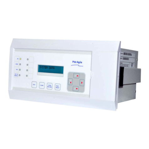
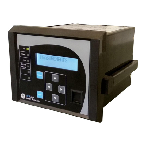
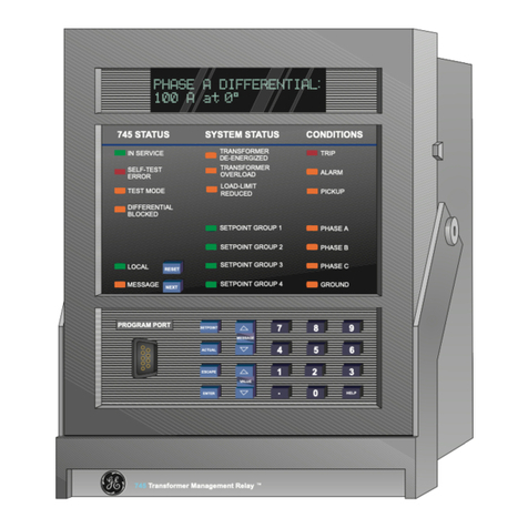
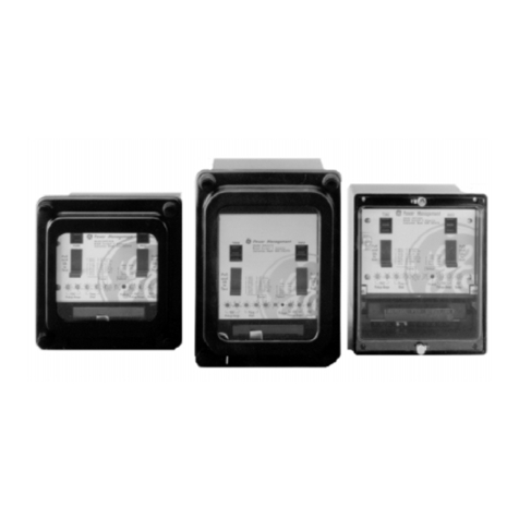
GE DFF1000 Series User manual

ÿ
GE Power Management
DFF series 1000
Instructions
InstructionsInstructions
Instructions
GEK 106166B
GEK 106166BGEK 106166B
GEK 106166B
Digital Frequency Relay
Digital Frequency RelayDigital Frequency Relay
Digital Frequency Relay

*(3RZHU0DQDJHPHQW
$Q\WKLQJ\RXFDQ·WILQG"
$Q\WKLQJQRWFOHDUHQRXJK"
,) <28 +$9( $1< &200(17 21 7+( &217(176 2) 7+(
35(6(17 0$18$/ .,1'/< )$; 86 $ &23< 2) 7+,6 3$*(
72*(7+(5 :,7+ $ &23< 2) 7+( 3$*( :+(5( <28 +$9(
)281' 7+( 352%/(0 72 7+( )$; 180%(5
),//,1*,17+(48(67,21$,5(%(/2::(:,//%(+$33<72
62/9( <285 '28%76 $1' :( 7+$1. <28 )25 +(/3,1* 86
,03529(7+,60$18$/
&RPSDQ\
1DPH
$GGUHVV
3KRQH
)D[
(PDLO
'HVFULSWLRQRI\RXUTXHVWLRQRUVXJJHVWLRQ
0DQXDO*(.FRGH


GEK – 106166B
1
TABLE OF CONTENTS
TABLE OF CONTENTSTABLE OF CONTENTS
TABLE OF CONTENTS
1. GENERAL DESCRIPTION AND APPLICATION 5
2. OPERATING PRINCIPLES 7
2.1 PROTECTION FUNCTIONS 7
2.1.1 FREQUENCY UNITS 7
2.1.2 VOLTAGE UNITS 9
2.2 INTERNAL STATUS 10
2.3 MONITORING AND REGISTERING FUNCTIONS 12
2.3.1 MEASUREMENT 12
2.3.2 LED SIGNALIZATION 12
2.3.3 SELF-CHECKING AND DIAGNOSIS 13
2.4 ANALYSIS FUNCTIONS 13
2.4.1 EVENT REGISTER 13
2.4.2 OSCILLOGRAPHY REGISTER.13
2.5 SETTING TABLES 14
2.6 INPUTS AND OUTPUTS 15
2.6.1 DIGITAL INPUTS 15
2.6.2 OUTPUTS 15
2.7 MAN MACHINE INTERFACE (MMI). 16
2.8 REMOTE COMMUNICATIONS 16
3. SETTINGS 17
4. EQUIPMENT CONFIGURATION 21
4.1 INPUTS CONFIGURATION 21
4.2 OUTPUTS CONFIGURATION 22
4.3 LEDSCONFIGURATION 22
5. TECHNICAL CHARACTERISTICS 23
5.1 MODEL LIST 23
5.2 TECHNICAL CHARACTERISTICS 24
6. HARDWARE DESCRIPTION 27
6.1 MECHANICAL CONSTRUCTION 27
6.1.1 BOX CONSTRUCTION.27
6.1.2 ELECTRICAL CONNECTIONS.27
6.1.3 INTERNAL CONSTRUCTION.27
6.1.4 IDENTIFICATION.29
6.1.5 MAGNETIC MODULE.29
6.1.6 PROTECTION CPU MODULE 29
6.1.7 COMMUNICATIONS CPU MODULE.30
6.1.8 INPUTS MODULE. 30
6.1.9 OUTPUTS MODULE.30
6.1.10 POWER SUPPLY.30
6.2 RECEPTION,OPERATION AND STORAGE.31
6.3 INSTALLATION 31

GEK – 106166B
2
7. ACCEPTANCE TESTS 33
7.1 CONNECTION AND NECESSARY EQUIPMENT 33
7.2 VISUAL CHECK 33
7.3 INSULATION TESTS.33
7.4 POWER SUPPLY 34
7.5 VOLTAGE MEASUREMENT 34
7.6 FREQUENCY MEASUREMENT.35
7.7 DIGITAL INPUTS CHECKING.35
7.8 OUTPUTS CHECKING.35
7.9 COMMUNICATIONS PORTS CHECKING.36
7.10 KEYPAD,DISPLAY AND LEDSCHECKING.36
7.11 CONTROL OPERATIONS.37
7.12 INHIBITION VOLTAGE CHECKING.37
7.13 VOLTAGE FUNCTIONS CHECKING.37
7.14 FREQUENCY UNITS CHECKING.38
8. INSTALLATION AND MAINTENANCE 39
8.1 INSTALLATION 39
8.2 GROUND CONNECTION FOR SAFETY AND PERTURBATION REMOVAL.39
8.3 MAINTENANCE 39
9. KEYPAD AND DISPLAY 41
9.1 TREE MENUS. 42
9.2 SETTINGS GROUP. 42
9.3 INFORMATION GROUP. 46
9.4 CONTROL OPERATIONS GROUP.47
9.5 SINGLE KEY OPERATIONS.47
9.6 CONFIGURATION UNIT.48

GEK – 106166B
3
TABLE LIST
TABLE LISTTABLE LIST
TABLE LIST
Table I : Communication internal states ................................................................................................................10
Table II : Protection internal states ........................................................................................................................11
Table III : Common settings to all tables ...............................................................................................................18
Table IV : Independent settings to each table ......................................................................................................19
FIGURE LIST
FIGURE LISTFIGURE LIST
FIGURE LIST
Fig. 1 : External connections for model DFF1000.................................................................................................49
Fig. 2 : External connections for model DFF1001.................................................................................................50
Fig. 3 : External connections for model DFF1002.................................................................................................51
Fig. 2 : Panel mounting..........................................................................................................................................52
Fig. 3 : RS-232 connection ....................................................................................................................................53
Fig. 4 : Dimensions................................................................................................................................................54
Fig. 5 : Front view ..................................................................................................................................................55
Fig. 6 : Rear view...................................................................................................................................................56

GEK – 106166B
4

GEK – 106166B
5
1.
1.1.
1. GENERAL DESCRIPTION AND
GENERAL DESCRIPTION ANDGENERAL DESCRIPTION AND
GENERAL DESCRIPTION AND
APPLICATION
APPLICATIONAPPLICATION
APPLICATION
During the last years new technologies have allowed a significant advance in the concept of integration between
different components of the electrical system. The reasons for such integration are several:
-Reduce the investment in new equipment.
-Optimize the use of the existing installations.
-Improve the energy management system.
This integration of functions not only includes the switchgear protection and control devices, but also the
monitoring elements, the alarm signalling equipment (with its associated treatment) and finally the analysis off all
the available information (events, alarms, oscillography, load and demand profiles, etc.).
The DFF is a microprocessor based protection relay used for frequency supervision in an electrical system. It
allows to create a customer-defined load shedding scheme.
Frequency variations are originated by unbalance conditions between generation and load. The main reasons for
this condition are:
•Inadequate load forecast or deficient generation capacity programming.
•Busbars, generator group or interconnection feeders trip.
•System split in different portions.
When the frequency variation is small, the unbalance condition will be corrected by the generator’s regulator. On
the contrary, in case of big frequency variations the regulator is not able to correct them itself, and the frequency
value will decrease with the danger of losing the generation capacity because of underfrequency tripping.
If this underfrequency condition is not corrected on time a general blackout may occur.
In case of shortage of generation capacity, the only possible way of recovering the stability of the system is
through a selective load shedding scheme. The load disconnection is done when the frequency goes down bellow
certain thresholds in order to provide reaction time to the generators, by means of the primary speed regulators.
It is important to point out that when the frequency decreases quickly the underfrequency condition is not enough
to recover stability. In this case the load shedding scheme must also take into account the frequency change rate.
This is done by calculating the frequency derivative over time. Loads are “shed” based not only on an absolute
(static) underfrequency threshold, but also on the dynamic frequency change rate.
The DFF is mainly used in medium voltage and distribution substations in order to implement a selective non-
critical load shedding scheme. By doing so, frequency recovers stability and we avoid potentially dangerous
situations that might affect generators or other parts of the electrical system.
The DFF available functions are:
a) Protection
•Eight underfrequency units, programmable as absolute or change rate values.
•Voltage unit to supervise frequency units.
•Undervoltage unit (Note: All protection functions use phase B for calculation).
•Overvoltage unit (Note: All protection functions use phase B for calculation).
GEK – 106166B
6
b) Monitorization and Register
•Phase and ground voltage measurement.
•Frequency measurement.
•Frequency change rate (derivative) measurement.
•17 LED indicators (16 of them user configurable).
•Self-checking and monitoring.
c) Analysis
•Events recording.
•Oscillography waveform capture.
•Alarm register.
d) Interfaces and Communications
The DFF has two communications ports. The front port is RS232 while the rear port can be RS232, RS485, plastic
or glass fiber optics.
The DFF associated software is the following:
•Communication software GE-LOCAL, that allows the user to view and modify the protection settings, alarms,
internal status etc.
•Configuration software GE-INTRO, that allows the user to configure the inputs, outputs, alarms and LEDs.
•Oscillography software GE-OSC, that allows the user to view and analyze waveform captured data.
These software packages are integral part of GE-NESIS software (General Electric NEtwork Substation
Integration System).

GEK – 106166B
7
2.
2.2.
2. OPERATING PRINCIPLES
OPERATING PRINCIPLESOPERATING PRINCIPLES
OPERATING PRINCIPLES
2.1 PROTECTION FUNCTIONS
2.1.1 FREQUENCY UNITS
The DFF relay incorporates 8 underfrequency units. Each unit can be independently set as ABSOLUTE
THRESHOLD or as DERIVATIVE. All frequency units are supervised by a voltage unit that disables the frequency
unit’s operation in case the voltage value decreases below the adjusted threshold. The available settings are:
Name Limits Default Step
FUNCTION TYPE FREC. or dF/dT FREC. N/A
81 PICKUP 40.00 - 70 Hz 50 Hz 0.01 Hz
TIME DELAY 0.00 - 60.00 s 1.00 s 0.01 s
dF/dT -10.00 to -0.10 Hz/s - 0.75
Hz/s 0.01 Hz/s
RESET TIME 0.00 - 600.00 s 0.00 s 0.01 s
NOTE: The measuring resolution of the DFF equipment is always better than 5 mHz. However, because of
esthetical reasons (in order to avoid fluctuations on the display) measures are displayed in steps of 10 mHz.
Nevertheless, the measurements in 5 mHz steps are reflected on the oscillogram.
•The FUNCTION TYPE setting allows to adjust the operation of the frequency unit as ABSOLUTE
THRESHOLD or DERIVATIVE
•The 81 PICKUP is the pickup value for both the underfrequency and the change rate units.
•The TIME DELAY is the time during which the fault condition must be present for the unit to trip.
•dF/dT is the instantaneous value of the frequency derivative over time that will cause a trip.
•RESET TIME is the time the frequency units maintain the tripping contacts closed, once the trip command has
been issued, and the condition that caused the trip has disappeared.
If we want to adjust a unit as change rate we will select the setting FUNCTION TYPE as dF/dT. In this case the
time delay setting is ignored and the trip is instantaneous (only the “number of semi-cycles” setting is taken into
account, this setting is common for all units. Please refer to the General Settings section).
In order to issue a trip in this operating mode the frequency has to be lower than the adjusted value in setting 81
PICKUP and also the frequency change rate over time must be higher than the setting value of dF/dT. We have to
take into account too that when frequency decreases the dF/dT value is negative and then the trip will be
instantaneous.
If we want a unit to operate as absolute frequency then we will select the setting FUNCTION TYPE as FREC.
Operating this way the adjusted value of dF/dT is ignored. The operating value of this unit would depend on the
adjusted value of TIME DELAY. The pickup will occur once the adjusted “number of semi-cycles” expire, (this is a
common setting for all units), and the trip will take place when the time delay ends (note that tripping conditions
should persist during all the time delay).
If we want one frequency unit producing two trips: one instantaneous and another time delayed, then we need to
address one output to the unit pickup and another independent output to the unit trip.
By doing so, as an example, if we have one unit adjusted as absolute underfrequency with a time delay of 10
seconds, the pickup will occur as soon as the frequency goes below the setting value during the adjusted number
of semi-cycles. Trip will take place after the 10 seconds' time delay. If the delay is adjusted to 0 seconds, then
pickup and trip will take place at the same time.

GEK – 106166B
8
If we want to adjust the unit as change rate, we will select the FUNCTION TYPE setting as dF/dT. The following
conditions are necessary for the unit to pickup in this mode:
•The frequency value must be under the set value for 81 PICKUP during the “number of semi-cycles” set for
GENERAL SETTINGS.
•The variation of frequency related to time must be higher (in absolute value) than the set value for dF/dT during
seven (7) semi-cycles less than the number of semi-cycles set in SEMY-CYCLES (General Settings)
If these conditions are present during the time set for TIME DELAY, the unit will trip.
In the following diagram, the operation mode for the dF/dT function is illustrated:
For the function set as absolute step, the bottom branch of the figure would always be active.
Comments:
nThe set number of semi-cycles is common for all the frequency units
nThe substracted semi-cycles in the dF/dT case, are due to the fact that for calculating the frequency, only one
cycle is need, while for calculating the dF/dT, we need at least 5 cycles.
nIf the voltage is under the value set for the inhibition unit, all the frequency units will be cancelled, but not the
voltage units.
nThe frequency, voltage, or frequency and voltage units can be disabled using the configurable inputs.
nOnce the fault condition has occurred, we must wait for a number of semi-cycles, adjusted in the No
SEMICYCLES of the General Settings, before starting the protection function. It may occur that the fault
condition disappears during this time; for example, if the dF/dT should be under -0.7Hz/s, and for a moment it
is only -0.65Hz/s. In this case, we may not want the protection function to be reset if the time during which the
fault condition disappears is very small. That's what the SEMICYCLES RESET setting is for. It allows the
semi-cycles counter to "freeze" without resetting during an adjustable time when the fault condition
disappears.
F < 81 Pickup
dF/dT < dF/dT Setting
Nº semi-cycles 0
Nº semi-cycles -70
Time Delay
Reset TRIP

GEK – 106166B
9
2.1.2 VOLTAGE UNITS
The DFF has 3 voltage units.
Inhibition voltage unit :
This unit supervises the phase voltage used for frequency calculation (in this case phase B). This unit is adjusted
as a percentage of the nominal voltage. The range goes from 40 to 110 % of the nominal voltage (also
adjustable). If the voltage measured in phase B goes below the setting, all frequency units will be inhibited.
Undervoltage unit :
This unit is applied only to phase B, that measures the frequency. The settings are as follows:
Name Limits Default Step
27P PICKUP 20 - 110 Vac 50 Vac 0.01 Vac
27P OPERATION t 0.00 - 30.00 s 5 s 0.01 s
27P RESET t 0 - 1200 s 0 s 1s
•The 27P PICKUP setting is the voltage operating value. If phase B measured voltage value goes below this
setting, the unit picks up.
•The 27P OPERATION t setting is the associated time delay for the undervoltage unit. The unit’s trip takes
place only after this time expires, taking into account that the voltage level should be lower than the setting
during the course of the time delay.
•The setting 27P RESET t is the time that the unit maintains the tripping contacts closed once the trip command
has been issued. Regardless the trip condition disappears or not, the contact will remain closed until the
expiration of this time.
Overvoltage units :
This unit is applied only to phase B, that measures frequency. The settings are the following:
Name Limits Default Step
PICKUP 59 F 50 - 220 Vac 80 Vac 0.01 Vac
59P OPERATION t 0.00 - 30.00 s 5 s 0.01 s
59P RESET t 0.00 - 30.00 s 0 s 0.01 s
•The PICKUP 597F setting is the voltage operating value. If phase B measured voltage value goes below this
setting the unit picks up.
•The 59P OPERATION t setting is the associated time delay for the overvoltage unit. The unit’s trip takes place
only after this time expires, taking into account that the voltage level should be higher than the setting during
the course of the time delay.
•The t. RESET 59F setting is the time that the unit maintains the tripping contacts closed once the trip
command has been issued. Regardless the trip condition disappears or not the contact will remain closed until
the expiration of this time.

GEK – 106166B
10
2.2 INTERNAL STATUS
The DFF is a microprocessor based relay that samples analog inputs, processes them by means of internal
algorithms and activates outputs accordingly. Most of the relay information may be accessed by the user in order
to create specific configurations for each application. With all this information the end-user can configure outputs,
inputs, LEDs and define alarms. All the programmable logic is based on AND, OR and NOT gates.
The DFF presents all this information as “Internal Status”. This is nothing but logical Boolean states of all the
internal variables available inside the relay. Each variable may be a “0” or a “1”. As an example, one internal state
is the pickup of a frequency unit. If this unit operates as underfrequency, its internal state will be “1”. This value
can be addressed to an output contact, an alarm or a LED.
By the same procedure if one digital input is activated, its “internal state” goes to “1”, and it can be addressed also
to an output contact, to an alarm or to a LED.
Programmable AND, OR and NOT logic can be done through the internal states information. For example,
activating one output when there is a pickup condition plus a digital input activation.
By adequate use of this “internal states” logic all kind of sophisticated load shedding schemes may be
implemented.
The DFF device has two different types of internal states:
•Protection internal states.
•General and communication internal states.
All those available communication internal states are shown in the following table:
TABLE I. COMMUNICATIONS INTERNAL STATES
Internal States Internal
States Internal States Internal
States
0 Mode: Remote (1)
Local (0) 20 40 60
1 Rear Connection 21 41 61
2 Front Connection 22 42 62
3234363
424Protection
link 44 64 LED 1
5 25 Control
link 45 65 LED 2
6264666LED3
7274767LED4
8284868LED5
9294969LED6
10 30 50 70 LED 7
11 31 51 71 LED 8
12 32 New
events 52 72 LED 9
13 33 53 73 LED 10
14 34 54 74 LED 11
15 35 55 75 LED 12
16 Time/date alarm 36 56 76 LED 13
17 37 57 77 LED 14
18 Serial EEPROM
alarm 38 58 78 LED 15
19 System Settings 39 59 79 LED 16

GEK – 106166B
11
All those available protection internal states are shown in the following table:
TABLE II. PROTECCION INTERNAL STATES
Internal States Internal
States Internal States Internal
States
0 Program Initiation 40 F1Trip 80 Output 13 120
1 Settings change 41 F2Trip 81 Output 14 121
2 42 F3Trip 82 Output 15 122
3 Configuration
change 43 F4Trip 83 Output 16 123
4 External trigger 44 F5Trip 84 Output 17 124
5 Communications
trigger 45 F6Trip 85 Output 18 125
6 46 F7Trip 86 Output 19 126
7 47 F8Trip 87 Output 20 127
8 48 27 Pickup 88 Output 21 128
9 49 59 Pickup 89 Output 22 129
10 50 90 Output 23 130
11 51 91 Output 24 131
12 52 92 Output 25 132
13 53 93 Output 26 133
14 54 94 Output 27 134
15 55 95 Output 28 135
16 Input 14 56 27 Trip 96 136
17 Input 13 57 59 Trip 97 Parallel E2PROM
Alarm 137
18 Input 12 58 98 Serial E2PROM
Alarm 138
19 Input 11 59 99 Out of order 139
20 Input 10 60 100 Default general
settings 140
21 Input 9 61 101 Table 1 default
settings 141
22 Input 8 62 102 Table 2 default
settings 142
23 63 103 Table 3 default
settings 143
24 Input 7 64 Output 1 104 Trip contact 144 AND1
25 Input 6 65 Output 2 105 Table 1 active 145 AND2
26 Input 5 66 Output 3 106 Table 2 active 146 AND3
27 Input 4 67 Output 4 107 Table 3 active 147 AND4
28 Input 3 68 Output 5 108 Trips disabled 148 AND5
29 Input 2 69 Output 6 109 149 AND6
30 Input 1 70 110 150 AND7
31 71 111 New events 151 AND8
32 F1 Pickup 72 Output 7 112 152 AND9
33 F2 Pickup 73 Output 8 113 153 AND10
34 F3 Pickup 74 Output 9 114 154 AND11
35 F4 Pickup 75 Output 10 115 155 AND12
36 F5 Pickup 76 Output 11 116 156 AND13
37 F6 Pickup 77 Output 12 117 157 AND14
38 F7 Pickup 78 118 158 AND15
39 F8 Pickup 79 119 159 AND16
NOTE: This table shows the internal states for model DFF1000, with 14 inputs and 33 outputs. Models DFF1001
(7 inputs and 25 outputs) and DFF1002 (7 inputs and 13 outputs) will show the associated states in blank.

GEK – 106166B
12
2.3 MONITORING AND REGISTERING FUNCTIONS
2.3.1 MEASUREMENT
The DFF provides measurement values for the following magnitudes:
•Three phase and ground voltages
•Frequency
•Frequency change rate over time
The DFF calculates RMS values for each phase. Measurement can be accessed through the local front display or
also from the GE_LOCAL communications software under the measurement screen. All the values are affected
by the external transformers´ ratio (PT PHASE RATIO and PT GROUND RATIO defined in the General Settings
Category).
2.3.2 LED SIGNALIZATION
The relay status provides information about all units inside the equipment (inputs, pickups, alarms, etc.). The
available signals in the status are packed together in groups of 16. In the status there are 10 of these groups; the
last group corresponds to the 16 configurable AND gates programmable through GE-INTRO software. To this last
group AND1....AND16 we can address the internal signals or also the output of another group’s AND.
In the DFF we have a total of 17 LEDs available, one bicolor (not configurable) for the internal alarm function plus
16 red. These 16 LEDs form a single column, and all of them are configurable using GE-INTRO software.
All events (32 originated by protection and 16 by communications), or an OR combination of them (maximum 16
inputs coming out from the same group) may be addressed to the LEDs.
Also we can select LED by LED whether we want memory on them or not. This impacts the way LEDs will operate
after a loss of the power supply. If they have memory, once the relay is powered up again the LEDs will recover
their previous states regardless the condition that made them operate still persists or not.
Also we can program the LEDs to blink just after the power up.
There is also a test facility for the LEDs, by pressing the TARGET RESET button all them will be lit. The same
button allows the reset of the LEDs signalling by pressing continuously during three seconds.
The default configuration of the DFF is the following:
LED DESCRIPTION LED DESCRIPTION
1 Frec. Pickup Function. 1 9 Frec. Trip Function. 1
2 Frec. Pickup Function. 2 10 Frec. Trip Function. 2
3 Frec. Pickup Function. 3 11 Frec. Trip Function. 3
4 Frec. Pickup Function 4 12 Frec. Trip Function. 4
5 Frec. Pickup Function. 5 13 Frec. Trip Function. 5
6 Frec. Pickup Function. 6 14 Frec. Trip Function. 6
7 Frec. Pickup Function. 7 15 Frec. Trip Function. 7
8 Frec. Pickup Function. 8 16 Frec. Trip Function. 8

GEK – 106166B
13
2.3.3 SELF-CHECKING AND DIAGNOSIS
The DFF includes (due to its numerical technology) self-checking and autodiagnosis. These functions guarantee
proper operation, signalization in case of internal failure and disable the operation of the protection functions.
These tests are performed not only during the power-up process of the relay but also during normal operation
(making use of the so called “background free time”). They check the situation of the power supply, ROM memory,
RAM memory, oscillography memory and the EEPROM memory.
Additionally a hardware check for the signalling LEDs is incorporated. By pressing the TARGET RESET button all
of them will be lit up.
2.4 ANALYSIS FUNCTIONS
2.4.1 EVENT REGISTER
The DFF relay has a cyclic register of the last 144 events, each event stores the following information: date and
time (1 msec time tag), type of event, the voltage, frequency, and dF/dT measurement values at the time event
happened and equipment status.
The events are stored in non-volatile EEPROM memory (the events are maintained even in the case of power
supply loss).
The generated events are associated with the internal states of protection and communications.
2.4.2 OSCILLOGRAPHY REGISTER.
There are two types of oscillos, selectable by the OSCILLO TYPE setting, between NORMAL or FREC.
NORMAL Type
The DFF unit can store up to 4 oscillography records, with a resolution of 16 samples per cycle. Each record has a
maximum capacity of 99 cycles, and the number of pre-fault cycles is selectable between 2 and 10. Each record
includes the following information:
•Instantaneous values of voltage inputs (VA,V
B
,V
C, VN):
•Frequency value
•Digital information (status of protection functions).
•Date and time
•Causes for the oscillography record.
•Active settings table in the moment of the record.
FREC Type
The DFF unit stores up to 4 oscillography records, with a resolution of 2 samples per cycle. Each record has a
maximum capacity of 1584 cycles, and the number of pre-fault cycles is selectable between 2 and 80. Each
record includes the following information:
•Frequency value
•Digital information (status of protection functions).
•Date and time.
•Causes for the oscillography record.
•Active settings table in the moment of the record.

GEK – 106166B
14
The trigger conditions for the waveform capture are:
Trigger through Input
Trigger through communications
81 Pickup Unit 1
81 Pickup Unit 2
81 Pickup Unit 3
81 Pickup Unit 4
81 Pickup Unit 5
81 Pickup Unit 6
81 Pickup Unit 7
81 Pickup Unit 8
81 Trip Unit 1
81 Trip Unit 2
81 Trip Unit 3
81 Trip Unit 4
81 Trip Unit 5
81 Trip Unit 6
81 Trip Unit 7
81 Trip Unit 8
27P Pickup
59P Pickup
Trigger Input
Trigger Communications
27P Trip
59P Trip
There is a configurable mask that defines what functions or internal trips can initiate the oscillography capture.
The available options are: configurable digital input, communications or local keypad.
The waveform captures registered are stored in COMTRADE format files by using GE-LOCAL communications
software. They can be viewed through GE-OSC software, any program that can read COMTRADE files or also as
a text file (using for example Microsoft EXCEL). Finally by means of an external format converter they will be
accepted by GLOBAL-LAB (a well known mathematical and signal analysis software package).
2.5 SETTING TABLES
The DFF provides three independent setting tables, stored in a non-volatile EEPROM memory. Only one table is
active at a time, and it is the one the relay uses.
Of all the settings available in the relay there are some of them common for the three setting tables (General
Settings, Active Table, Oscillography Masks and Functions’ Enabling). The rest of settings are independent for
each table.
There is a setting called “ACTIVE TABLE” that allows to define which is the active table at a certain time.
There is another way of changing the active table. By using two digital inputs, called “TABLE 0 SELECTION” and
“TABLE 1 SELECTION” up to four different (0 to 3) combinations are possible. To do this, those inputs must be
programmed to perform such function. In applications that require only two different tables only one digital input is
needed (leaving the second input free for other uses).
The selected combination is obtained from the following table:
Number Input 1 Input 0 Active Table
0 0 0 Selected by setting
10 1 1
21 0 2
31 1 3
NOTE: If any of these two digital inputs is active, the selection will have priority over the “ACTIVE TABLE” setting.
That setting will have no meaning.

GEK – 106166B
15
2.6 INPUTS AND OUTPUTS
2.6.1 DIGITAL INPUTS
The DFF1000 has 14 digital inputs (two groups of 7 Inputs each with a common terminal for each), being all of
them user-configurable through GE-INTRO software program. Models DFF1001 and DFF1002 have only 7 inputs.
Every input may have one of the following values:
- Input non-active
- External Trigger ( Pulse )
- Table 0 selection ( Level )
- Table 1 selection ( Level )
- Frequency trips block ( Level)
- Voltage trips block ( Level )
- Complete protection trips block ( Level )
The external connections diagrams, in figures 1, 2, and 3, show the default inputs configuration.
2.6.2 OUTPUTS
The DFF1000 provides 33 Outputs, five of them are not configurable (four of them are assigned to the protection
functions and one of them is for the internal alarm). The rest of the available outputs, 28, are configurable through
GE-INTRO software. Models DFF1001 and DFF1002 provide 25 (20 configurable, 5 fixed) and 13 (8 configurable,
5 fixed) outputs each.
The technical characteristics of the outputs are described in chapter 5.
The configurable outputs may be programmed through a logic based on the internal states of the relay (pickups,
trips, alarms, etc.). The DFF has 132 different internal states, all of them can be combined through NOT, AND and
OR logic gates providing huge flexibility.
The programmable logic is done at different levels. At the first level AND gates (of up to 16 inputs previously
grouped, see 2.2.3) can be done. The output of this AND gate is incorporated to a state bit, that can be also
incorporated to another AND gate of, again, up to 16 Inputs. This “star-connection” process can be repeated until
finishing the 16 bits of the predefined status for this function.
Once finished the AND gates configuration process a second level can be implemented using OR gates of also up
to 16 Inputs. In this case the inputs are limited to the previously created bytes groups.
In the external connection drawings (Figures 1, 2, and 3) the default output configurations are shown.

GEK – 106166B
16
2.7 MAN MACHINE INTERFACE (MMI).
The DFF relay includes a 20-button keypad with a two-line screen (16 characters per line). The screen has
background light by LED diodes (the brightness can be adjusted through a power meter accessible at the back of
the front board).
Through this interface, the user can change settings, visualize actual values, access the stored information, etc.
The description of how to perform these operations is described in the KEYPAD AND DISPLAY section of this
book.
2.8 REMOTE COMMUNICATIONS
The relay has two serial communications ports. Port 1 is accessible at the relay front through a DB9 connector 1
(PORT1). Port 2 is accessed at the relay back through another connector (PORT 2).
There are different models depending on the physical media of connector PORT 2 (RS-232, RS-485 or fiber
optics). In models “only RS232” all connectors are RS232. For models “RS232 and fiber optics” or “RS-232 and
RS-485”, connector PORT1 is RS232 while PORT2 is either a fiber optics connector or a RS-485 one.
Connector for PORT1 has priority above connector PORT2 and is selected once DCD signal (Data Carrier
Detect) is activated. In figure 3 there is a sketch of how to make a connection to a personal computer.
Ports 1 and 2 are fully independent and can be used at the same time.
The relay is in local communication when we are using either the MMI or the front port and in remote
communication every time we use the rear port.
Both types of communication can be active at the same time, however the possibility of changing settings or
performing control operations is limited only to the communication mode with higher priority (local mode). The
other channel then will only have access to the information.
Once the local communication is interrupted, either by the disconnection of PORT 1 connector or by returning the
MMI to the initial screen (done on purpose or automatically after 15 minutes without any button being pressed), the
remote communication mode recovers its lost privileges of being able to change settings or perform control
operations.

GEK – 106166B
17
3.
3.3.
3. SETTINGS
SETTINGSSETTINGS
SETTINGS
The following tables contain a complete list of the DFF settings, with their associated ranges, units and steps. The
column called DEFAULT shows the factory default settings.
Setting can be viewed and modified in different ways: through keypad and display or through a computer
connected to any of the two available serial ports. In order to modify settings manually please refer to section 9
“KEYPAD AND DISPLAY”. To modify settings through a computer the following steps should be followed:
•Make sure the connection cable corresponds to the one described in figure 3, either for DB9 or DB25.
•Connect the cable between the relay (or modem) and the computer serial port.
•Execute GE-LOCAL software. For more information about GE-LOCAL software check with the instruction
manual GEK 105595.
•Make sure the configuration parameters of the relay and the ones of the software match. Those settings are :
- UNIT NUMBER
- PASSWORD
- BAUD RATE (different settings for local and remote communications )
- STOP BIT (different settings for local and remote communications )
To view or modify the configuration settings please go to the configuration menu, please refer to section 9
“KEYPAD AND DISPLAY”
The DFF relay has three independent setting tables stored in non-volatile EEPROM memory. Those tables are
selectable through settings or configurable inputs. the following categories contain the common settings to the
three tables:
GENERAL SETTINGS
ACTIVE TABLE SETTINGS
OSCILLOGRAPHY MASK
FUNCTION ENABLING
The rest of categories, indicated here below, contain the settings that can be selected independently for every
table:
•Undervoltage unit 27P
•Overvoltage unit 59P
•Underfrequency unit or dF/dT 81 U1
•Underfrequency unit or dF/dT 81 U2
•Underfrequency unit or dF/dT 81 U3
•Underfrequency unit or dF/dT 81 U4
•Underfrequency unit or dF/dT 81 U5
•Underfrequency unit or dF/dT 81 U6
•Underfrequency unit or dF/dT 81 U7
•Underfrequency unit or dF/dT 81 U8
It is important to mention that in order to simplify the menu and also for safety reasons, all settings connected to
configuration (I/O, LEDs, events) have been taken out from the keypad.
This manual suits for next models
3
Table of contents
Other GE Relay manuals