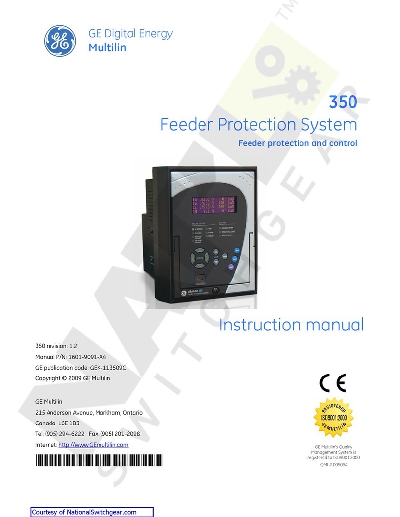
GE Multilin DFF User manual

GE Multilin
215 Anderson Avenue
L6E 1B3 Markham, ON -CANADA
Tel: (905) 294 6222 Fax: (905) 294 8512
E-mail: [email protected]
Internet: www.GEMultilin.com
Copyright © 2004 GE Multilin
DFF
Digital Frequency Relay
Instruction manual
GEK-106166E
GE Multilin
Avda. Pinoa, 10
48170 Zamudio SPAIN
Tel: +34 94 485 88 00 Fax: +34 94 485 88 45
E-mail: [email protected]
gGE Consumer & Industrial
Multilin

TABLE OF CONTENTS
GEK-106166E DFF Digital Feeder Relay 1
1. GENERAL DESCRIPTION AND APPLICATION 5
2. OPERATING PRINCIPLES AND SETTINGS 7
2.1 PROTECTION FUNCTIONS 8
2.1.1 FREQUENCY UNITS 8
2.1.2 VOLTAGE UNITS 10
2.2 STATUS AND ACTUAL VALUES 11
2.2.1 MEASUREMENT 11
2.2.2 TARGET LEDS 11
2.2.3 SELF-CHECKING AND DIAGNOSIS 12
2.3 ANALYSIS FUNCTIONS 12
2.3.1 EVENT LOGS 12
2.3.2 OSCILLOGRAPHY 12
2.4 SETTING TABLES 13
2.5 INPUTS AND OUTPUTS 14
2.5.1 DIGITAL INPUTS 14
2.5.2 OUTPUTS 14
2.6 MAN MACHINE INTERFACE (MMI). 14
2.7 REMOTE COMMUNICATIONS 14
3. SETTINGS 15
4. EQUIPMENT CONFIGURATION 19
4.1 INPUTS CONFIGURATION 22
4.2 OUTPUTS CONFIGURATION 22
4.3 LEDS CONFIGURATION 23
5. TECHNICAL CHARACTERISTICS 25
5.1 MODEL LIST / ORDERING CODE 25
5.2 TECHNICAL CHARACTERISTICS 26
6. HARDWARE DESCRIPTION 29
6.1 MECHANICAL CONSTRUCTION 29
6.1.1 CASE CONSTRUCTION. 29
6.1.2 ELECTRICAL CONNECTIONS. 29
6.1.3 INTERNAL CONSTRUCTION. 29
6.1.4 IDENTIFICATION. 31
6.1.5 MAGNETIC MODULE. 31
6.1.6 PROTECTION CPU MODULE 31
6.1.7 COMMUNICATIONS CPU MODULE. 32
6.1.8 INPUT MODULE. 32
6.1.9 OUTPUT MODULE. 32
6.1.10 POWER SUPPLY. 32
7. ACCEPTANCE TESTS 33
7.1 VISUAL CHECK 33
7.2 CONNECTION AND NECESSARY EQUIPMENT 33
7.3 INSULATION TESTS. 34
7.4 POWER SUPPLY 35

TABLE OF CONTENTS
2 DFF Digital Feeder Relay GEK-106166E
7.5 VOLTAGE MEASUREMENT 35
7.6 FREQUENCY MEASUREMENT. 36
7.7 DIGITAL INPUT CHECKS. 36
7.8 OUTPUT CHECKS. 36
7.9 COMMUNICATIONS PORTS CHECKS. 37
7.10 KEYPAD, DISPLAY AND LED CHECKS. 38
7.11 CONTROL OPERATIONS. 39
7.12 INHIBIT VOLTAGE CHECK. 39
7.13 VOLTAGE FUNCTION CHECKS. 40
7.14 FREQUENCY UNITS CHECKS. 41
8. INSTALLATION AND MAINTENANCE 43
8.1 RECEPTION, OPERATION AND STORAGE. 43
8.2 INSTALLATION 43
8.3 GROUND CONNECTION FOR SAFETY AND PERTURBATION REMOVAL. 43
8.4 MAINTENANCE 43
9. KEYPAD AND DISPLAY 45
9.1 TREE MENUS. 46
9.2 SETTINGS MENU GROUP. 47
9.2.1 ENTERING SETTINGS MANUALLY 54
9.3 INFORMATION GROUP. 54
9.4 CONTROL OPERATIONS GROUP. 56
9.5 SINGLE KEY OPERATIONS. 57
9.6 COMMUNICATIONS MENU. 57
10. FIGURES 59

TABLE OF CONTENTS
GEK-106166E DFF Digital Feeder Relay 3
TABLE LIST
Table I: Communication internal states.................................................................................................................10
Table II: Protection internal states ........................................................................................................................11
Table III: Common settings to all tables................................................................................................................20
Table IV: Independent settings to each table .......................................................................................................21
FIGURE LIST
Fig. 1: External connections for DFF1000 model .................................................................................................56
Fig. 2: External connections for DFF1001 model .................................................................................................57
Fig. 3: External connections for DFF1002 model .................................................................................................58
Fig. 4: External connections for DFF1003 model .................................................................................................59
Fig. 5: External connections for DFF 1012 model ................................................................................................60
Fig. 6: External connections for DFF 1011 model ................................................................................................61
Fig. 7: Panel mounting for 19” rack models..........................................................................................................62
Fig. 8: RS232 connection......................................................................................................................................63
Fig. 9: Dimensions diagram for 19” rack models ..................................................................................................64
Fig. 10: Dimensions diagram for ½ rack models ..................................................................................................65
Fig. 11: Front view for 19” rack models.................................................................................................................66
Fig. 12: Rear view for 19” rack models.................................................................................................................67
Fig. 13: Front view for ½ rack models...................................................................................................................68
Fig. 14: Rear view for ½ rack models ...................................................................................................................69

TABLE OF CONTENTS
4 DFF Digital Feeder Relay GEK-106166E

GENERAL DESCRIPTION AND APPLICATION
GEK-106166E DFF Digital Feeder Relay 5
1. GENERAL DESCRIPTION AND APPLICATION
New technology has allowed a significant advance in the concept of integration between different components of the
electrical system. The reasons for such integration are several:
• Reduce the investment in new equipment.
• Optimize the use of the existing installations.
• Improve the energy management system.
This integration of functions not only includes the switchgear protection and control devices, but also the monitoring
elements, the alarm signalling equipment (with its associated treatment) and finally the analysis of all the available
information (events, alarms, oscillography, load and demand profiles, etc.).
The DFF is a multi-microprocessor based protection relay used for frequency supervision in an electrical system.
Frequency variations originate from unbalance conditions between generation and load. The main reasons for this
condition are:
• Inadequate load forecast or deficient generation capacity programming.
• Busbars, generator group or interconnection feeders trip.
• System splits into islands.
When the frequency variation is small, the unbalance condition will be corrected by the generator’s regulator. In the
case of big frequency variations, the regulator is not able to correct itself, and the frequency value will decrease with
the danger of losing generation capacity.
If this underfrequency condition is not corrected, then a general blackout may occur.
In case of a shortage of generation capacity, the only possible way of recovering the stability of the system is through
a selective load shedding scheme. The load disconnection is done when the frequency goes down below certain
thresholds in order to provide adequate reaction time for the generators to recover via their speed regulators.
It is important to point out that when the frequency decreases quickly, relays operation based on the detection of
underfrequency condition may not be enough to recover stability. In this case the load shedding scheme must also
take into account the rate of change of frequency. This is done by calculating the frequency derivative over time.
Loads are “shed” based not only on an absolute (static) underfrequency threshold, but also on the dynamic rate of
change of frequency.
The DFF is mainly used in medium voltage and distribution substations as a selective load shedding scheme. By
doing so, frequency recovers stability and potentially dangerous situations that might affect generators in other parts
of the electrical system are avoided.

GENERAL DESCRIPTION AND APPLICATION
6 DFF Digital Feeder Relay GEK-106166E
The DFF available functions are:
a) Protection
• Eight underfrequency units, settable as absolute or rate of change.
• Voltage unit to supervise frequency units.
• Undervoltage unit.
• Overvoltage unit.
b) Status/Actual Values
• Phase and ground voltage measurement.
• Frequency measurement.
• Frequency rate of change measurement.
• 17 LED indicators (16 of them user configurable).
• Self-checking and monitoring.
c) Post-Event Analysis
• Events Log.
• Oscillography: Waveform Capture or Frequency Trending.
d) Interfaces and Communications
The DFF has three communications ports:
• RS232 on the front panel
• RS232 on the rear
• Fiber Optic/RS485 option on the rear (selected by order code).
DFF support Software:
• Communication software GE-LOCAL and DFFPC (view and modify the protection settings, alarms,
internal status, measurements, etc.)
• Configuration software GE-INTRO (configure the inputs, outputs, alarms and LEDs.)
• Oscillography software GE-OSC (view and analyze waveform captured data.) The oscillography is
stored in a file in COMTRADE format (IEEE C37.111-1991 Standard).
These software packages are integral part of GE-NESIS software (General Electric NEtwork Substation Integration
System).

OPERATING PRINCIPLES
GEK-106166E DFF Digital Feeder Relay 7
2. OPERATING PRINCIPLES AND SETTINGS
DFF relay measures frequency by detecting the voltage zero crossings and measuring the time between them. When
the frequency is detected to be below the setting, the relay starts counting for how many consecutive half-periods
(semi cycles) it continues below the setting. There is a setting called “SEMICYCLES SET” to adjust the number of
half-periods for the unit to pickup.
It is possible that the frequency transiently restores and goes above the underfrequency threshold. If this occurs, the
DFF freezes the counter to pickup and starts counting the number of semi cycles to reset the unit. If the count of semi
cycles to reset reaches the value set in the setting “SEMICYCLES RESET” then the unit is reset. On the other hand,
if the frequency goes again below the threshold, the DFF will continue the count of semi cycles to set, from where it
was left.
If the “SEMI CYCLES SET” count is reached the pickup signal of the unit is activated and the relay starts the count of
the time delay set independently for each frequency unit.
When the time delay expires, the trip signal of the unit is activated.
The “SEMICYCLES SET” and “SEMICYCLES RESET” settings are common for the eight frequency units.
The time delay (TIME DELAY and RESET TIME) are independent for each one of the eight units.
The relay provides the PICKUP signal and the TRIP signal for each one of the eight units as internal digital signals, to
allow the user to configure the output contacts as required for each application.
GE INTRO software must be used to change the factory default configuration of output contacts or LEDs.
The following functional block diagram shows the operation of the relay, as described above, and shows the PICKUP
and TRIP signals for each unit.
Drawing: 301A8000
FIGURE 2.1. DFF FUNCTIONAL BLOCK DIAGRAM

OPERATING PRINCIPLES
8 DFF Digital Feeder Relay GEK-106166E
2.1 PROTECTION FUNCTIONS
2.1.1 FREQUENCY UNITS
The DFF relay incorporates 8 underfrequency units. All frequency units are supervised by a voltage unit that inhibits
the frequency units in case the voltage decreases below the threshold.
The main settings for the frequency elements are:
GENERAL SETTINGS GROUP (Common to all Protection Functions of the relay)
Name Limits Default Step
RELAY STATUS NO SERV / IN SERV NO SERV N/A
FREQUENCY 50 / 60 Hz 50 N/A
NOMINAL VOLTAGE 90 – 220 Vac 90 1
INHIBIT V 40 – 110 % 40 % 1
SEMICYCLES SET 3 – 20 3 1
SEMICYCLES RESET 0 – 4 0 1
PHASE VT RATIO 1 – 4000 1000 1
GROUND VT RATIO 1 – 4000 1000 1
SETTINGS FOR EACH INDIVIDUAL FREQUENCY ELEMENT (for example 81 N1)
Name Limits Default Step
FUNCTION TYPE FREQ. Or dF/dT FREQ. N/A
81 PICKUP 40.00 – 70.00 Hz 50 Hz 0.01 Hz
TIME DELAY 0.00 - 60.00 s 1.00 s 0.01 s
dF/dT -10.00 to -0.10 Hz/s - 0.75 Hz/s 0.01 Hz/s
RESET TIME 0.00 - 600.00 s 0.00 s 0.01 s
NOTE: The measuring resolution of the DFF equipment is always better than 5 mHz. However to avoid fluctuations
on the LCD display, the frequency is displayed in steps of 10 mHz. Measurements in 5 mHz steps are reflected on
the oscillogram.

OPERATING PRINCIPLES
GEK-106166E DFF Digital Feeder Relay 9
GENERAL SETTINGS DESCRIPTION
• RELAY STATUS: The relay can be switched in or out of service (NO SERV / IN SERV)
• FREQUENCY: Defines the nominal frequency of the network ( 50 Hz / 60 Hz )
• NOMINAL VOLTAGE: Defines the secondary phase-phase Vac nominal voltage applied to the relay.
• INHIBIT V: The relay incorporates an inhibit voltage element with a user settable threshold INHIBIT V.
• SEMICYCLES SET: The DFF includes a counter that increments in semi cycles during an underfrequency
situation. For example 5 semi cycles of 50Hz is equivalent to 50ms delay. This acts as a time delay to filter
spurious variations in the input signal to the frequency unit. The counter is initially frozen if the frequency restores
and it is reset by the operation of the SEMICYCLES RESET counter. This counter activates the Frequency
Element pick up signal when the count exceeds the SEMICYCLES SET threshold.
• SEMICYCLES RESET: The DFF includes a counter that increments in semi cycles when the frequency restores.
This counter resets the SEMICYCLES SET counter when the count exceeds the SEMICYCLES RESET
threshold.
• PHASE VT RATIO: Defines the ratio of the HV phase voltage transformer.
• GROUND VT RATIO: Defines the ratio of the HV zero sequence voltage transformer.
SETTINGS FOR EACH INDIVIDUAL FREQUENCY ELEMENT (for example 81 N1)
• The FUNCTION TYPE setting adjusts the operation of the frequency unit as absolute frequency or rate of change
of frequency (df/dt).
• The 81 PICKUP is the pickup value for the unit if it is set as FREQ and for the underfrequency supervision
element if it is set as df/dt.
• The TIME DELAY is the intentional time delay of the unit to produce a trip after pick up.
• dF/dT is the instantaneous value of the rate of change of frequency that will produce a trip if the FUNCTION
TYPE is set as df/dt, and the supervision elements have operated.
• RESET TIME is the time the frequency units maintain the tripping signal after the condition that caused the trip
has disappeared.
OPERATION IN FREQ MODE:
Select the setting FUNCTION TYPE as FREQ. (The setting value of dF/dT is now ignored). The operation time of
this unit will depend on the setting of TIME DELAY. The pickup will occur once the adjusted “number of semi-cycles”
expire, (common setting for all units), and the trip will take place when the time delay ends (note that tripping
conditions should persist during all the time delay).
OPERATION IN DF/DT MODE:
To adjust a unit as rate of change select the setting FUNCTION TYPE as dF/dT.
In order to issue a trip in this operating mode the frequency has to be lower than the adjusted value in setting 81
PICKUP AND the rate of change of frequency must be more negative than the setting value of dF/dT.

OPERATING PRINCIPLES
10 DFF Digital Feeder Relay GEK-106166E
2.1.2 VOLTAGE UNITS
The DFF has 3 voltage units.
Inhibit voltage unit :
This unit supervises the phase voltage used for frequency calculation (phase B, of ABC). This unit is adjusted in the
GENERAL SETTINGS menu as described above. It is set as a percentage of the nominal voltage. The range goes
from 40 to 110 % of the nominal voltage (also adjustable). If the voltage measured in phase B goes below the setting,
all frequency units will be inhibited.
Undervoltage unit :
This unit measures phase B voltage. The settings are as follows:
Name Limits Default Step
27P PICKUP 20.00 – 110.00 Vac 50 Vac 0.01 Vac
TIME DELAY 27P 0.00 - 30.00 s 5 s 0.01 s
RESET TIME 27P 0 - 1200 s 0 s 1 s
• The 27P PICKUP setting is the voltage operating value. If phase B measured voltage value goes below this
setting, the unit picks up.
• The TIME DELAY 27P setting is the associated time delay for the undervoltage unit. The unit’s trip takes place
only after this time expires, taking into account that the voltage level must be lower than the setting during the
course of the time delay.
• The RESET TIME 27P setting is the time that the unit maintains the tripping contacts closed once the trip
command has been issued and the undervoltage condition has disappeared.
Overvoltage units :
This unit measures phase B voltage. The settings are as follows:
Name Limits Default Step
PICKUP 59P 50.00 – 220.00 Vac 80 Vac 0.01 Vac
TIME DELAY 59P 0.00 – 30.00 s 5 s 0.01 s
RESET TIME 59P 0.00 – 30.00 s 0 s 0.01 s
• The PICKUP 59P setting is the voltage operating value. If phase B measured voltage value goes above this
setting the unit picks up.
• The TIME DELAY 59P setting is the associated time delay for the overvoltage unit. The trip takes place only after
this time expires. The voltage level must be higher than the setting during the course of the time delay.
• The RESET TIME 59P setting is the time that the unit maintains the tripping contacts closed once the trip
command has been issued and the overvoltage condition has disappeared.

OPERATING PRINCIPLES
GEK-106166E DFF Digital Feeder Relay 11
STATUS AND ACTUAL VALUES
2.2.1 MEASUREMENT
The DFF provides measurement values for:
• Three phase voltages
• One ground voltage
• Frequency
• Rate of change of frequency
The DFF calculates the fundamental frequency RMS voltage phasor for each phase and for ground. Measurement
can be accessed through the local front display and from the GE_LOCAL or DFFPC communications software. All
the values are affected by the external transformers´ ratio (PHASE VT RATIO and GROUND VT RATIO defined in
GENERAL SETTINGS).
2.2.2 TARGET LEDS
In the DFF, a total of 17 LEDs are available, one bicolor LED (red/green)for the internal alarm function plus 16 red
LED’s configured as the table shown below.
LEDs configured for trip indication (9 to 16) include a memory feature, and they remain lit until the user presses the
TARGET RESET button for 3 seconds.
The memory feature covers also for lost of Vdc auxiliary power.
There is a test facility for the LEDs, by pressing the TARGET RESET button for less than 3 seconds, all LED’s will be
lit without being reset.
The factory default configuration of the DFF is the following:
LED DESCRIPTION MEMORY LED DESCRIPTION MEMORY
1 Pickup L1 NO 9 Trip L1 YES
2 Pickup L2 NO 10 Trip L2 YES
3 Pickup L3 NO 11 Trip L3 YES
4 Pickup L4 NO 12 Trip L4 YES
5 Pickup L5 NO 13 Trip L5 YES
6 Pickup L6 NO 14 Trip L6 YES
7 Pickup L7 NO 15 Trip L7 YES
8 Pickup L8 NO 16 Trip L8 YES

OPERATING PRINCIPLES
12 DFF Digital Feeder Relay GEK-106166E
2.2.3 SELF-CHECKING AND DIAGNOSIS
The DFF includes self-checking and auto-diagnosis.
These tests are performed during the power-up process of the relay and during normal operation. They check the
status of the power supply, ROM memory, RAM memory, oscillography memory and the EEPROM memory.
In case of an internal failure these functions detect the failure, disable the operation of the protection functions and
warn the user by operating the ALARM contact (terminals C9-D9).
2.3 ANALYSIS FUNCTIONS
2.3.1 EVENT LOGS
The DFF relay has a circular log of the latest 144 events. Each event stores the following information:
• Date and time (1 msec resolution)
• Type of event
• Voltage
• Frequency
• dF/dT measurement
• Status of all internal digital signals (trips, pickups, inputs, outputs, etc.).
The events are stored in non-volatile EEPROM memory.
2.3.2 OSCILLOGRAPHY
There are two types of record selectable by the OSCILLO TYPE setting: NORMAL or FREQ.
NORMAL Type
The DFF unit can store up to 4 oscillography records, with a resolution of 16 samples per cycle. Each record has a
maximum capacity of 99 cycles, and the number of pre-fault cycles is selectable between 2 and 10. Each record
includes the following information:
• Waveforms of instantaneous samples of AC voltage inputs (VA, VB, VC, VN):
• Frequency value at instant of trigger.
• Digital channels indicating status of protection functions.
• Date and time.
• Trigger source.
• Active settings.

OPERATING PRINCIPLES
GEK-106166E DFF Digital Feeder Relay 13
FREQ Type
The DFF unit stores up to 4 oscillography records, with a resolution of 2 samples per cycle. Each record has a
maximum capacity of 1584 cycles, and the number of pre-fault cycles is selectable between 2 and 80. Each record
includes the following information:
• Frequency trend computed every semi-cycle.
• Digital channels indicating status of protection functions.
• Date and time.
• Trigger source.
• Active settings.
To start an oscillography record, the user can set up to 24 signals that will act as a trigger. For details see Chapter 2
-LIST OF SETTINGS.
The waveforms are stored in a file in COMTRADE format (IEEE C37.111-1991 Standard).The oscillography record
must be retrieved from the DFF relay by using GE-LOCAL or DFFPC communications software. They can be viewed
through GE-OSC software or any program that can read COMTRADE files. They can also be imported from
Microsoft EXCEL.
2.4 SETTING TABLES
The DFF provides three independent setting tables, TABLE 1, TABLE 2, TABLE 3, stored in non-volatile EEPROM
memory. Only one table is active at one time.
There are some settings that are common for the three setting tables: GENERAL SETTINGS, ACTIVE TABLE,
OSCILLOGRAPHY MASK and FUNCTION PERMIT. The rest of settings are independent for each table.
There is a setting called ACTIVE TABLE that defines which table is being applied.
There is another way of changing the active table. By using up to two digital inputs, called “TABLE 0 SELECTION”
and “TABLE 1 SELECTION” up to four different (0 to 3) combinations are possible.
The selected combination is obtained from the following table:
Number TABLE 1 SELECTION TABLE 0 SELECTION TABLE APPLIED
0 0 0
ACTIVE TABLE setting
1 0 1 1
2 1 0 2
3 1 1 3
NOTE: If any of the two digital inputs is active the “ACTIVE TABLE” setting is ignored

OPERATING PRINCIPLES
14 DFF Digital Feeder Relay GEK-106166E
2.5 INPUTS AND OUTPUTS
2.5.1 DIGITAL INPUTS
The DFF family of relays can have a variety of digital inputs. For details see ordering code in section 5 - MODEL
LIST. The minimum number of inputs is 7 and the maximum is 14 (two groups of 7 Inputs each with a common
terminal for each group). See chapter 4 for details on advanced configuration options.
2.5.2 OUTPUTS
The DFF family of relays provides a variety of digital outputs. For details see ordering code in section 5 - MODEL
LIST. The minimum number of outputs is 13 and the maximum is 33. Four outputs are pre-assigned to the protection
function trips and one for the internal alarm. See chapter 4 for details on advanced configuration options.
2.6 MAN MACHINE INTERFACE (MMI).
The DFF relay includes a 20-button keypad with a two-line LCD display (16 characters per line). The background of
the LCD is back lit by LEDs. The contrast can be adjusted through a trimmer accessible behind the front board.
Through this interface, the user can change settings, visualize actual values, etc. Refer to KEYPAD AND DISPLAY
section.
2.7 REMOTE COMMUNICATIONS
The relay has up to 3 serial communications ports. PORT 1 is accessible at the front of the relay PORTs 2 and 3 are
accessed at the rear of the relay.
There are different models depending on the physical media of connector PORT 2 (RS-232, RS-485 or fiber optics).
See ordering code at section 5 - MODEL LIST.
The connector for PORT1 has priority over connector port2 and is selected once DCD signal (Data Carrier Detect) is
activated. See figure 8 for required connections. Use the cable configuration described in the figure or use a standard
direct RS-232 cable (no crossings) and a standard Null-Modem adaptor.
PORTS 1 and 2 are fully independent and can be used at the same time. PORT 3 is switched with PORT 1.
The relay is in local communication when using either the MMI or the front port.
Both local and remote communication can be active at the same time, however the possibility of changing settings or
performing control operations is limited only to the communication mode with higher priority (local mode). The other
channel then will only have access to read the information.
Once the local communication is interrupted, either by the disconnection of port 1 connector or by returning the MMI
to the initial screen (done manually pressing CLR key or automatically after 15 minutes without any button being
pressed), the remote communication mode recovers its lost privileges of being able to change settings or perform
control operations.

SETTINGS
GEK-106166E DFF Digital Feeder Relay 15
3. SETTINGS
Setting can be viewed and modified in different ways: through the keypad and display or through a computer
connected to a serial port. In order to modify settings manually please refer to section 9 “KEYPAD AND DISPLAY”.
The DFF relay has three independent setting tables, TABLE 1, TABLE 2, TABLE 3, stored in non-volatile EEPROM
memory. The active table is selected through the ACTIVE TABLE setting or with the TABLE 0 SELECTION or
TABLE 1 SELECTION digital inputs. The following groups of settings are common to the three tables:
• GENERAL SETTINGS
• ACTIVE TABLE SETTING
• OSCILLOGRAPHY MASK
• FUNCTION PERMIT
The settings that can be selected independently for each table are:
• 27P - Undervoltage unit
• 59P - Overvoltage unit
• 81N1 - Underfrequency unit or dF/dT
• 81 N2 - Underfrequency unit or dF/dT
• 81N3 - Underfrequency unit or dF/dT
• 81N4 - Underfrequency unit or dF/dT
• 81N5 - Underfrequency unit or dF/dT
• 81N6 - Underfrequency unit or dF/dT
• 81N7 - Underfrequency unit or dF/dT
• 81N8 - Underfrequency unit or dF/dT
The following tables contain a complete list of the DFF settings common for the three tables, with their associated
ranges, units and steps. The column called DEFAULT shows the factory default settings:

SETTINGS
16 DFF Digital Feeder Relay GEK-106166E
Table III . Common settings for all tables
Setting type DESCRIPTION RANGE Factory Default Step
GENERAL SETTINGS
RELAY STATUS Put the relay IN or OUT
of service NO SERV / IN SERV NO SERV N/A
FREQUENCY Nominal frequency 50 / 60 Hz 50 Hz N/A
IDENTIFICATION (can
only be changed via a
PC)
Alphanumeric string of
20 characters N/A Identification N/A
NOMINAL VOLTAGE Nominal ph-ph voltage 90 - 220 Vac 90 Vac 1 V
INHIBIT V voltage inhibition of
frequency functions 40 - 110 % 40 % 1 %
SEMICYCLES SET Number of semi-cycles
for the frequency units
operation
3 - 20 3 1
SEMICYCLES RESET Number of reset cycles
for the frequency units
reset
0-4 01
PHASE VT RATIO VT phase ratio 1 - 4000 1000 1
GROUND VT RATIO VT ground ratio 1 - 4000 1000 1
ACTIVE TABLE
SETTING DESCRIPTION RANGE Factory Default Step
ACTIVE TABLE Activates a table of
settings 1 - 3 1 1
FUNCTION PERMIT DESCRIPTION RANGE Factory Default Step
27P FUNCTION To enable 27P Enabled / Disabled Disabled N/A
59P FUNCTION To enable 59P Enabled / Disabled Disabled N/A
81N1 FUNCTION To enable 81N1 Enabled / Disabled Disabled N/A
81N2 FUNCTION To enable 81N2 Enabled / Disabled Disabled N/A
81N3 FUNCTION To enable 81N3 Enabled / Disabled Disabled N/A
81N4 FUNCTION To enable 81N4 Enabled / Disabled Disabled N/A
81N5 FUNCTION To enable 81N5 Enabled / Disabled Disabled N/A
81N6 FUNCTION To enable 81N6 Enabled / Disabled Disabled N/A
81N7 FUNCTION To enable 81N7 Enabled / Disabled Disabled N/A
81N8 FUNCTION To enable 81N8 Enabled / Disabled Disabled N/A
27P TRIP To enable 27P TRIP YES/NO YES N/A
59P TRIP To enable 59P TRIP YES/NO YES N/A
81N1 TRIP To enable 81N1 TRIP YES/NO YES N/A
81N2 TRIP To enable 81N2 TRIP YES/NO YES N/A
81N3 TRIP To enable 81N3 TRIP YES/NO YES N/A
81N4 TRIP To enable 81N4 TRIP YES/NO YES N/A
81N5 TRIP To enable 81N5 TRIP YES/NO YES N/A
81N6 TRIP To enable 81N6 TRIP YES/NO YES N/A
81N7 TRIP To enable 81N7 TRIP YES/NO YES N/A
81N8 TRIP To enable 81N8 TRIP YES/NO YES N/A
OSCILLOGRAPHY
MASK DESCRIPTION RANGE Factory Default Step
TYPE OF OSCILLO Define type of oscillo.
Voltage
Waveforms/Frequency
Trending
NORMAL/FREQ NORMAL N/A

SETTINGS
GEK-106166E DFF Digital Feeder Relay 17
Setting type DESCRIPTION RANGE Factory Default Step
PREFAULT CYCLES Number of prefault
cycles 2- 10 (NORMAL)
2-80 (FREQ) 4 1
81N1 PICKUP 81N1 PU triggers
oscillography YES/NO YES N/A
81N2 PICKUP 81N2 PU triggers
oscillography YES/NO YES N/A
81N3 PICKUP 81N3 PU triggers
oscillography YES/NO YES N/A
81N4 PICKUP 81N4 PU triggers
oscillography YES/NO YES N/A
81N5 PICKUP 81N5 PU triggers
oscillography YES/NO YES N/A
81N6 PICKUP 81N6 PU triggers
oscillography YES/NO YES N/A
81N7 PICKUP 81N7 PU triggers
oscillography YES/NO YES N/A
81N8 PICKUP 81N8 PU triggers
oscillography YES/NO YES N/A
81N1 TRIP 81N1 TRIP triggers
oscillography YES/NO YES N/A
81N2 TRIP 81N2 TRIP triggers
oscillography YES/NO YES N/A
81N3 TRIP 81N3 TRIP triggers
oscillography YES/NO YES N/A
81N4 TRIP 81N4 TRIP triggers
oscillography YES/NO YES N/A
81N5 TRIP 81N5 TRIP triggers
oscillography YES/NO YES N/A
81N6 TRIP 81N6 TRIP triggers
oscillography YES/NO YES N/A
81N7 TRIP 81N7 TRIP triggers
oscillography YES/NO YES N/A
81N8 TRIP 81N8 TRIP triggers
oscillography YES/NO YES N/A
27P PICKUP 27P PU triggers
oscillography YES/NO YES N/A
59P PICKUP 59P PU triggers
oscillography YES/NO YES N/A
INPUT TRIGGER INPUT triggers
oscillography YES/NO YES N/A
COMMUNICATIONS
TRIGGER PC or MMI can trigger
oscillography YES/NO YES N/A
27P TRIP 27P TRIP triggers
oscillography YES/NO YES N/A
59P TRIP 59P TRIP triggers
oscillography YES/NO YES N/A

SETTINGS
18 DFF Digital Feeder Relay GEK-106166E
Table IV. INDEPENDENT SETTINGS FOR EACH TABLE (TABLE 1, TABLE 2, TABLE 3)
Setting type DESCRIPTION RANGE Factory Default Step
27P FUNCTION UNDERVOLTAGE
27P PICKUP 27P Pickup 20 to 110 Vac 50 1 Vac
TIME DELAY 27P Operating time 0 to 30 s 5 0.01 s
RESET TIME 27P Reset time after
fault disappears 0 to 1200 s 0 1 s
59P FUNCTION OVERVOLTAGE
59P PICKUP 59P Pickup 50 to 220 Vac 80 1 Vac
TIME DELAY 59P Operating time 0 to 30 s 5 0.01 s
RESET TIME 59P Reset time after
fault disappears 0 – 30 s 0 0.01 s
81NX FUNCTIONS * FREQUENCY
FUNCTION TYPE Type: Freq. or
Rate of change FREQ / dF/dT FREQ N/A
81 PICKUP 81 Pickup 40 to 70 Hz 50 Hz 0.01 Hz
TIME DELAY Operating time 0 to 60 s 1.00 s 0.01 s
DF/DT Rate of Change -0.1 to -10 Hz/s -1 Hz/s 0.01 Hz/s
RESET TIME Reset time after
fault disappears 0 to 600 s 0 0.01 s
• 8 independent frequency units are provided within each table, 81N1, 81N2, 81N3, 81N4, 81N5, 81N6, 81N7
and 81N8.

EQUIPMENT CONFIGURATION
GEK-106166E DFF Digital Feeder Relay 19
4. EQUIPMENT CONFIGURATION
The DFF is a microprocessor-based relay that samples analog inputs, processes them by means of internal
algorithms and activates outputs accordingly. Most of the relay information may be accessed by the user in order to
create special configurations of inputs, outputs and LEDs, using AND, OR and NOT logical gates. The DFF presents
this information as “Internal Status”, which is a set of logical Boolean states of all the internal variables available
inside the relay. Each variable may be a “0” or a “1”. As an example, one internal state is the pickup of a frequency
unit. If this unit operates as underfrequency, its internal state will be “1”. This value can be configured to close an
output contact or lit an LED.
In the same way if one digital input is activated, its “internal state” goes to “1”, and it can be configured also to close
an output contact or to lit an LED.
The DFF device has two different types of internal states:
• Protection internal states.
• General and communication internal states.
The following tables show the list of the internal signals available.
Table of contents
Other GE Relay manuals