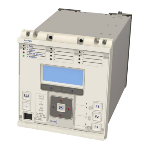
GE 750 User manual

750/760
Feeder Management Relay
QUICK REFERENCE GUIDE
Software Revision: 7.0x
Manual P/N: 1601-0131-A6
Manual Order Code: GEK-106477E
Copyright © 2006 GE Multilin
GE Multilin
215 Anderson Avenue, Markham, Ontario
Canada L6E 1B3
Tel: (905) 294-6222 Fax: (905) 201-2098
Internet: http://www.GEmultilin.com
ISO9001:2000
G
E
M
U
L
T
I
L
I
N
R
E
G
I
S
T
E
R
E
D
GE Multilin's Quality Management
System is registered to
ISO9001:2000
QMI # 005094
UL # A3775


Table of contents
750/760 Quick Reference Guide 1
TABLE OF CONTENTS
OVERVIEW.................................................................................................................................................. 1
Introduction........................................................................................................................................................ 1
Description .......................................................................................................................................................... 1
Protection and control function summary.......................................................................................... 1
Monitoring and control function summary.........................................................................................2
MECHANICAL INSTALLATION ............................................................................................................ 2
Drawout case .................................................................................................................................................... 2
Mounting.............................................................................................................................................................. 3
Unit withdrawal and insertion ................................................................................................................... 4
Ethernet connection....................................................................................................................................... 5
ELECTRICAL INSTALLATION................................................................................................................ 6
Ratings and polarities.................................................................................................................................... 6
Logic inputs ........................................................................................................................................................ 8
Analog inputs and outputs.......................................................................................................................... 8
ACCESSING SETPOINTS VIA THE FRONT PANEL........................................................................8
TYPICAL APPLICATION SETUP ........................................................................................................... 9
System setpoints ............................................................................................................................................. 9
Logic input setpoints....................................................................................................................................10
Protection setpoints......................................................................................................................................10
ENERVISTA 750/760 SETUP SOFTWARE INTERFACE ........................................................... 11
Overview ............................................................................................................................................................11
Hardware...........................................................................................................................................................11
CONNECTING ENERVISTA 750/760 SETUP TO THE RELAY................................................ 13
Configuring Serial Communications.....................................................................................................13
Using the Quick Connect feature ...........................................................................................................15
Configuring Ethernet communications ...............................................................................................15
Connecting to the relay ..............................................................................................................................17
WORKING WITH SETPOINTS AND SETPOINT FILES .............................................................. 18
Engaging a device.........................................................................................................................................18
Entering setpoints..........................................................................................................................................18
File support .......................................................................................................................................................19
Using setpoints files......................................................................................................................................20
UPGRADING RELAY FIRMWARE..................................................................................................... 24
Description........................................................................................................................................................24
Saving setpoints to a file ............................................................................................................................25
Loading new firmware ................................................................................................................................25

Table of contents
2 750/760 Quick Reference Guide
ADVANCED ENERVISTA 750/760 SETUP FEATURES............................................................. 26
Triggered events............................................................................................................................................ 26
Waveform capture (trace memory)...................................................................................................... 27
Data logger ...................................................................................................................................................... 30
Event recorder ................................................................................................................................................ 30
Modbus user map......................................................................................................................................... 31
Viewing actual values ................................................................................................................................. 32
APPLICATION EXAMPLE..................................................................................................................... 33
Description ....................................................................................................................................................... 33
Power system data ...................................................................................................................................... 40
Control system requirements.................................................................................................................. 40
Instrument transformer data .................................................................................................................. 40
Phase protection settings ......................................................................................................................... 40
Neutral protection settings....................................................................................................................... 41
S2 System setpoints .................................................................................................................................... 41
S3 Logic Inputs setpoints........................................................................................................................... 42
S5 Protection setpoints............................................................................................................................... 45
OTHER SETTINGS ................................................................................................................................. 50
Description ....................................................................................................................................................... 50
Undervoltage protection ........................................................................................................................... 50
Auxiliary relays............................................................................................................................................... 51
Changing setpoint groups ........................................................................................................................ 52
INSTALLATION....................................................................................................................................... 53
TECHNICAL SUPPORT ........................................................................................................................ 54

Overview
750/760 Quick Reference Guide 1
OVERVIEW
Introduction
This Quick Reference Guide takes you through the installation and setup of your GE Multilin
750/760 Feeder Mangement Relay and helps you get it up and running as quickly as
possible. The following topics are covered:
• Installing the 750/760
• Installing the EnerVista 750/760 Setup software
• Setting up the 750/760
This guide contains only basic instructions. For complete information, refer to the 750/760
Feeder Mangement Relay instruction manual (GE Publication number GEK-106293E).
Description
The 750/760 Feeder Mangement Relay is a microprocessor-based unit intended for the
management and primary protection of distribution feeders, as well as for management
and backup protection of buses, transformers, and transmission lines. The 760 relay is
particularly suited to overhead feeders, where automatic reclosing is normally applied.
Each relay provides protection, control, and monitoring functions with both local and
remote human interfaces. They also display the present trip/alarm conditions, and most of
the more than 35 measured system parameters. Recording of past trip, alarm or control
events, maximum demand levels, and energy consumption is also performed.
To aid new users in setting up basic protection, setpoints are set to typical default values
and advanced features are disabled. These settings can be reprogrammed at any time.
Programming can be accomplished with the front panel keys and display or, to simplify
programming and provide a more intuitive interface, setpoints can be entered with a PC
running the no-charge EnerVista 750/760 Setup software provided with the relay. Actual
values and setpoints can be displayed, altered, stored, and printed. If settings are stored in
a setpoint file, they can be downloaded at any time to the front panel program port of the
relay via a computer cable connected to the serial port of any personal computer.
Protection and control function summary
ANSI Description
27 Bus / line undervoltage
47 Negative-sequence voltage
50 Phase/neutral/ground/negative-sequence/sensitive ground instantaneous overcurrent
50BF Breaker failure with current supervision
51 Phase/neutral/ground/negative-sequence/sensitive ground time overcurrent
59 Bus overvoltage / neutral displacement
67 Phase/neutral/negative-sequence/sensitive ground/ground directional control
81 Bus underfrequency / rate of change
--- Undervoltage automatic restoration
--- Underfrequency automatic restoration
--- Bus transfer
--- Programmable logic inputs
--- Multiple setpoint groups

Mechanical installation
2 750/760 Quick Reference Guide
Monitoring and control function summary
MECHANICAL INSTALLATION
Drawout case
The 750/760 is packaged in the standard GE Multilin SR-series arrangement, which consists
of a drawout relay and a companion case. The case provides mechanical protection for the
drawout portion and is used to make permanent electrical connections to external
equipment. Where required, case connectors are fitted with mechanisms, such as
automatic CT shorting, to allow the safe removal of the relay from an energized panel.
There are no electronic components in the case.
Figure 1: Case dimensions
ANSI Description
25 Synchrocheck
50 Phase/neutral current level
55 Power factor
79 Autoreclose (760 only)
81 Overfrequency
Breaker open/close
Manual close feature blocking
Cold load pickup feature blocking
Breaker operation failure
Trip/Close circuit failure
Total breaker arcing current
VT failure
Demand (current, real power, reactive power, apparent power)
Analog input
Event recording
Analog output
Fault locator
Trip counter

Mechanical installation
750/760 Quick Reference Guide 3
Mounting
The 750/760 can be mounted alone or adjacent to another SR-series relay on a standard
19-inch rack panel. The dimensions of the panel cutout, for both conditions, are shown
below. When planning the location of your panel cutout, ensure provision is made for the
front door to swing open without interference to or from adjacent equipment.
Figure 2: Single and double unit panel cutouts
Before mounting the relay in the supporting panel, remove the unit from the case.
From the front of the panel, slide the empty case into the cutout. To ensure the case's front
bezel sits flush with the panel, apply pressure to the bezel's front while bending the
retaining tabs 90°. These tabs are located on the sides and bottom of the case and appear
as shown in the illustration. After bending all tabs, the case will be securely mounted so that
its relay can be inserted. The relay is now ready for panel wiring.
Figure 3: Mounting Tabs

Mechanical installation
4 750/760 Quick Reference Guide
Unit withdrawal and insertion
TURN OFF CONTROL POWER BEFORE DRAWING OUT OR RE-INSERTING THE
RELAY TO PREVENT MALOPERATION!
If an attempt is made to install a relay into a non-matching case, the case’s
configuration pin will prevent full insertion. Applying a strong force in this
instance will result in damage to the relay and case.
If using an ethernet connection, refer to Ethernet connection on page 5 before starting the
following procedure.
To remove the unit from the case:
1. Open the door by pulling from the top or bottom of its right side. It will rotate to the left
about its hinges.
2. Press upward on the locking latch, which is located below the handle, and hold in its
raised position. The tip of a small screwdriver may prove helpful in this operation.
Figure 4: Press latch up and pull handle
3. With the latch raised, pull the center of the handle outward. Once disengaged,
continue rotating the handle up to the stop position.
Figure 5: Rotating handle to stop position
CAUTION
CAUTION

Mechanical installation
750/760 Quick Reference Guide 5
4. When the stop position is reached, the locking mechanism will release. The relay will
now slide out of the case when pulled from its handle. To free the relay, it may
sometimes be necessary to adjust the handle position slightly.
Figure 6: Sliding the Unit out of the Case
To insert the unit into the case:
1. Ensure that the model number on the left side of the relay matches the requirements
of the installation.
2. Raise the locking handle to the highest position.
3. Hold the unit immediately in front of the case and align the rolling guide pins (near the
hinges of the relay’s handle) with the case’s guide slots.
4. Slide the unit into the case until the guide pins on the unit have engaged the guide
slots on either side of the case.
5. Once fully inserted, grasp the handle from its center and rotate it down from the
raised position towards the bottom of the relay.
6. Once the unit is fully inserted the latch will be heard to click, locking the handle in the
final position. The unit is mechanically held in the case by the handle’s rolling pins,
which cannot be fully lowered to the locked position until the electrical connections
are completely mated.
No special ventilation requirements need to be observed during the
installation of the unit. The unit does not require cleaning.
Ethernet connection
If using the 750/760 with the Ethernet 10Base-T option, ensure that the network cable is
disconnected from the rear RJ45 connector before removing the unit from the case. This
prevents any damage to the connector.
The unit may also be removed from the case with the network cable connector still
attached to the rear RJ45 connector, provided that there is at least 16" of network cable
available when removing the unit from the case. This extra length allows the network cable
to be disconnected from the RJ45 connector from the front of the switchgear panel. Once
disconnected, the cable can be left hanging safely outside the case for re-inserting the unit
back into the case.
NOTE

Electrical installation
6 750/760 Quick Reference Guide
The unit may then be re-inserted by first connecting the network cable to the units' rear
RJ45 connector (see step 3 of Unit withdrawal and insertion on page 4).
Ensure that the network cable does not get caught inside the case while sliding
in the unit. This may interfere with proper insertion to the case terminal blocks
and damage the cable.
Figure 7: Ethernet Cable Connection
ELECTRICAL INSTALLATION
Ratings and polarities
Ensure that the control voltage matches the ratings and polarities of the relay power
supply. Control power supplied to the relay must match the installed power supply range.
All grounds MUST be connected for normal operation regardless of control power supply
type. The label found on the left side of the relay specifies its order code or model number.
The installed power supply's operating range will be one of the following.
• LO: 20 to 60 V DC or 20 to 48 V AC
• HI: 88 to 300 V DC or 70 to 265 V AC
The relay ground connections should be connected directly to the ground bus, using the
shortest practical path. A tinned copper, braided, shielding and bonding cable should be
used. As a minimum, 96 strands of number 34 AWG should be used. Belden catalog number
8660 is suitable.
The current transformer input ratings and polarities match the secondary ratings of the
corresponding CT. For the correct operation of many relay features, the instrument
transformer polarities shown below in the Typical Wiring Diagram should be followed.
IMPORTANT: The phase and ground current inputs will correctly measure to 20 times
the current input's nominal rating.
CAUTION

Electrical installation
750/760 Quick Reference Guide 7
Figure 8: Typical wiring diagram
The phase sequence is user programmable to be either ABC or ACB rotation.
The voltage transformer input ratings must match the secondary ratings of the VT. The 750/
760 relays have four channels for AC voltage inputs, each with an isolating transformer. The
nominal secondary voltage must be in the 50 to 240 V range. The three phase inputs are
designated as the “bus voltage”. The Bus VT connections most commonly used, wye and
delta (or open delta), are shown in the Typical Wiring Diagram. Be aware that these voltage
channels are internally connected as wye. This is why the jumper between the phase B
terminal and the Vcom terminal must be installed with a delta connection.

Accessing setpoints via the front panel
8 750/760 Quick Reference Guide
Logic inputs
Logic inputs are connected as indicated below. Ensure correct polarity and do not connect
any logic input circuits to ground or else relay hardware may be damaged. External
contacts can be connected to the relay's fourteen (14) logic inputs. As shown, these
contacts can be either dry or wet. It is also possible to use a combination of both contact
types.
Figure 9: Dry and wet contact connections
Analog inputs and outputs
Analog Inputs and Outputs are connected as indicated in the Typical Wiring Diagram. Also
refer to the figure below. Note that the shield of the cable shall be grounded at one point
only, usually at the PLC/computer end only.
Figure 10: Analog output connections
ACCESSING SETPOINTS VIA THE FRONT PANEL
Refer to Chapter 1 750/760 instruction manual for details on changing setpoints. To have
access to the relay setpoints, you must install a hardware jumper across terminals C10 and
C11 at the back of the relay case. Attempts to enter a new setpoint without this electrical
connection will result in an error message. Additional information is provided in the same
section regarding passcodes and accessing information via the serial ports of the relay.
Dry Contact Connection Wet Contact Connection
750/760 RELAY750/760 RELAY
C12
C1C1
C12 +32VDC
+32VDC
Logic Input 1
Logic Input 1
32VDC
32VDC
DC Negative
DC Negative D12
D12
30 to 300 V DC
LOGICIN.CD
R

Typical application setup
750/760 Quick Reference Guide 9
TYPICAL APPLICATION SETUP
System setpoints
At a minimum, the S2 SYSTEM SETUP setpoints must be entered for the system to function
correctly. To safeguard against the installation of a relay whose setpoints have not been
entered, the “Relay Not Ready” self-test warning is displayed. In addition, the Self-Test
Warning relay will be de-energized.
Once the relay has been programmed for the intended application, the S1 RELAY SETUP Z
INSTALLATION ZV 760 OPERATION setpoint should be changed from “Not Ready” (the
default) to “Ready”. Before putting the relay in the Ready state, each page of setpoint
messages should be worked through, entering values either by keypad or computer.
The same change can be done using the EnerVista 750/760 Setup software. Select the
Setpoints > Relay Setup > Installation > 750760 Operation menu item to access the
following page:
The relay leaves the factory with setpoints programmed to default values, and it is these
values that are shown in all the setpoint message illustrations. Many of these factory
default values can be left unchanged.
For a typical example on how to set the 750/760 for feeder protection, refer to the
Application example on page 33. In addition to providing typical wiring diagrams, the
example covers the procedure to set the following features of the 750/760.
• System setup for phase, neutral and ground CTs: CT primary ratings, CT secondary
ratings, and CT turn ratio.
• System setup for VTs: VT primary ratings, VT secondary ratings, and VT turn ratio.
Setpoints can be accessed with the EnerVista 750/760 Setup software. To access the
setpoints listed above, select the Setpoints > System Setup > 750/760 System Setup
menu item:

Typical application setup
10 750/760 Quick Reference Guide
Logic input setpoints
The logic input setpoints include the logic input identification, logic input asserted logic, and
logic input functionality. To set logic inputs by means of the EnerVista 750/760 Setup
software, select the Setpoints > Logic Inputs menu item. The setpoints are shown as sub-
pages of the following tree:
Protection setpoints
Refer to the Application example on page 33 for details on how to set the 750/760 Feeder
Mangement Relay for a typical overcurrent protection of a distribution feeder.
The EnerVista 750/760 Setup software can be used to set the overcurrent protection
elements. For example, select the Setpoints > Protection > Phase Currents menu item. The
setpoints will appear as tabs in the corresponding window:

EnerVista 750/760 Setup software interface
750/760 Quick Reference Guide 11
A similar process can be followed to enable other protection and control features. For a
complete description of setpoints and their functionality, refer to Chapter 5 of the 750/760
instruction manual.
ENERVISTA 750/760 SETUP SOFTWARE INTERFACE
Overview
The EnerVista 750/760 Setup software provides a graphical user interface (GUI) as one of
two human interfaces to a 750/760 device. The alternate human interface is implemented
via the device's faceplate keypad and display (see the first section in this chapter).
The EnerVista 750/760 Setup software provides a single facility to configure, monitor,
maintain, and trouble-shoot the operation of relay functions, connected over serial
communication networks. It can be used while disconnected (i.e. off-line) or connected (i.e.
on-line) to a 750/760 device. In off-line mode, settings files can be created for eventual
downloading to the device. In on-line mode, you can communicate with the device in real-
time.
This no-charge software, provided with every 750/760 relay, can be run from any computer
supporting Microsoft Windows®95 or higher. This chapter provides a summary of the basic
EnerVista 750/760 Setup software interface features. The EnerVista 750/760 Setup Help File
provides details for getting started and using the EnerVista 750/760 Setup software
interface.
With the EnerVista 750/760 Setup running on your PC, it is possible to:
• Program and modify setpoints
• Load/save setpoint files from/to disk
• Read actual values and monitor status
• Perform waveform capture and log data
• Plot, print, and view trending graphs of selected actual values
• Download and playback waveforms
• Get help on any topic
Hardware
Communications from the EnerVista 750/760 Setup to the 750/760 can be accomplished
three ways: RS232, RS485, and Ethernet communications. The following figures below
illustrate typical connections for RS232, RS485, and Ethernet communications.
RS485 COM2 is disabled when the Ethernet option is ordered.
NOTE

EnerVista 750/760 Setup software interface
12 750/760 Quick Reference Guide
Figure 11: Communications using the front RS232 port
Figure 12: Communications using rear RS485 port

Connecting EnerVista 750/760 Setup to the Relay
750/760 Quick Reference Guide 13
Figure 13: Communications using rear Ethernet port
CONNECTING ENERVISTA 750/760 SETUP TO THE RELAY
Configuring Serial Communications
Before starting, verify that the serial cable is properly connected to either the RS232 port on
the front panel of the device (for RS232 communications) or to the RS485 terminals on the
back of the device (for RS485 communications). See Hardware on page 11 for connection
details.
This example demonstrates an RS232 connection. For RS485 communications, the GE
Multilin F485 converter will be required. Refer to the F485 manual for additional details. To
configure the relay for Ethernet communications, see Configuring Ethernet communications
on page 15.
1. Install and start the latest version of the EnerVista 750/760 Setup software (available
from the GE EnerVista CD). See the previous section for the installation procedure.
2. Click on the Device Setup button to open the Device Setup window and click the Add
Site button to define a new site.
3. Enter the desired site name in the Site Name field. If desired, a short description of site
can also be entered along with the display order of devices defined for the site. In this
example, we will use “Substation 1” as the site name. Click the OK button when
complete.
4. The new site will appear in the upper-left list in the EnerVista 750/760 Setup window.
5. Click the Add Device button to define the new device.
6. Enter the desired name in the Device Name field and a description (optional) of the
site.
996711A1.CDR

Connecting EnerVista 750/760 Setup to the Relay
14 750/760 Quick Reference Guide
7. Select “Serial” from the Interface drop-down list. This will display a number of
interface parameters that must be entered for proper RS232 functionality.
Enter the slave address and COM port values (from the S1 RELAY SETUP ZV
COMMUNICATIONS ZV PORT SETUP menu) in the Slave Address and COM Port
fields.
Enter the physical communications parameters (baud rate and parity settings) in their
respective fields.
8. Click the Read Order Code button to connect to the 750/760 device and upload the
order code. If an communications error occurs, ensure that the 750/760 serial
communications values entered in the previous step correspond to the relay setting
values.
9. Click OK when the relay order code has been received. The new device will be added
to the Site List window (or Online window) located in the top left corner of the main
EnerVista 750/760 Setup window.
The 750/760 Site Device has now been configured for serial communications. Proceed to
Connecting to the relay on page 17 to begin communications.

Connecting EnerVista 750/760 Setup to the Relay
750/760 Quick Reference Guide 15
Using the Quick Connect feature
The Quick Connect button can be used to establish a fast connection through the front
panel RS232 port of a 750/760 relay. The following window will appear when the Quick
Connect button is pressed:
As indicated by the window, the Quick Connect feature quickly connects the EnerVista 750/
760 Setup software to a 750/760 front port with the following settings: 9600 baud, no
parity, 8 bits, 1 stop bit. Select the PC communications port connected to the relay and
press the Connect button.
The EnerVista 750/760 Setup software will display a window indicating the status of
communications with the relay. When connected, a new Site called “Quick Connect” will
appear in the Site List window. The properties of this new site cannot be changed.
The 750/760 Site Device has now been configured via the Quick Connect feature for serial
communications. Proceed to Connecting to the relay on page 17 to begin communications.
Configuring Ethernet communications
Before starting, verify that the Ethernet cable is properly connected to the RJ-45 Ethernet
port.
1. Install and start the latest version of the EnerVista 750/760 Setup software (available
from the GE EnerVista CD). See the previous section for the installation procedure.
2. Click on the Device Setup button to open the Device Setup window and click the Add
Site button to define a new site.
3. Enter the desired site name in the Site Name field. If desired, a short description of site
can also be entered along with the display order of devices defined for the site. In this

Connecting EnerVista 750/760 Setup to the Relay
16 750/760 Quick Reference Guide
example, we will use “Substation 2” as the site name. Click the OK button when
complete.
4. The new site will appear in the upper-left list.
5. Click the Add Device button to define the new device.
6. Enter the desired name in the Device Name field and a description (optional).
7. Select “Ethernet” from the Interface drop-down list. This will display a number of
interface parameters that must be entered for proper Ethernet functionality.
Enter the IP address, slave address, and Modbus port values assigned to the 750/760
relay (from the S1 RELAY SETUP ZV COMMUNICATIONS ZV NETWORK
CONFIGURATION menu).
8. Click the Read Order Code button to connect to the 750/760 and upload the order
code. If an communications error occurs, ensure that the Ethernet communications
values correspond to the relay setting values.
9. Click OK when the relay order code has been received. The new device will be added
to the Site List window (or Online window) located in the top left corner of the main
EnerVista 750/760 Setup window.
The 750/760 Site Device has now been configured for Ethernet communications. Proceed
to the following section to begin communications.
To ensure optimal response from the relay, the typical connection timeout should
be set as indicated in the following table:
TCP/IP sessions Timeout setting
up to 2 2 seconds
up to 4 3 seconds
NOTE
Other manuals for 750
5
This manual suits for next models
1
Table of contents
Other GE Relay manuals