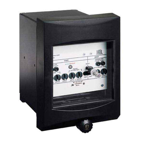
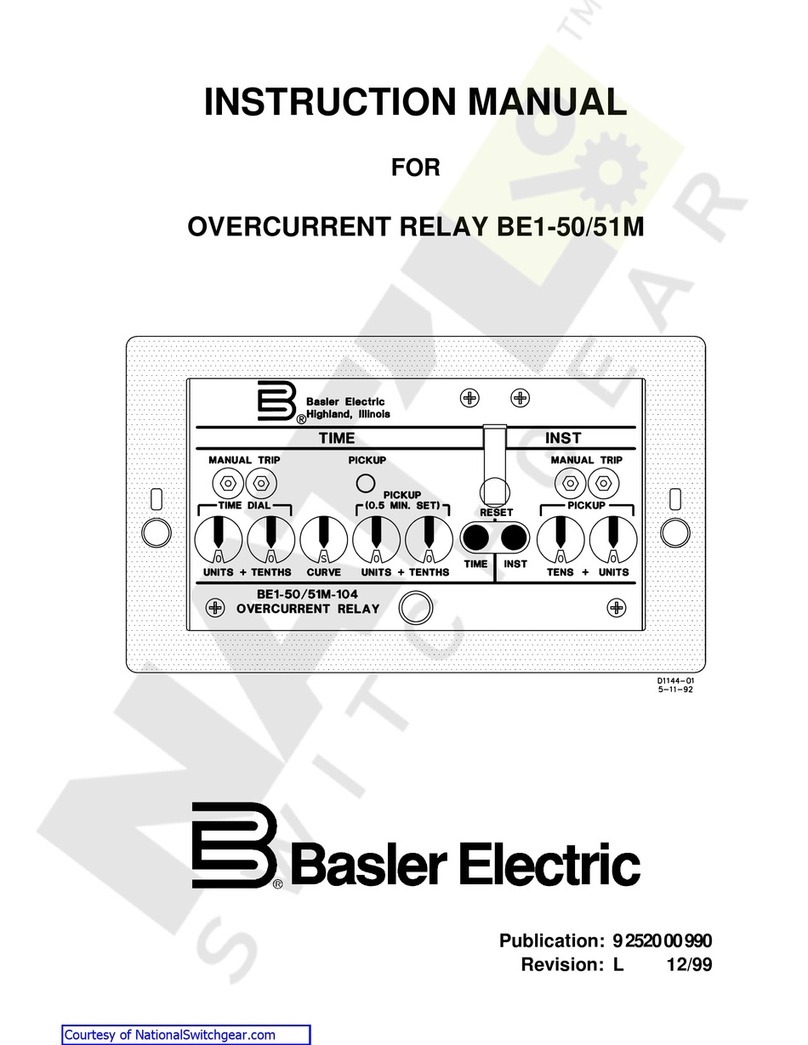
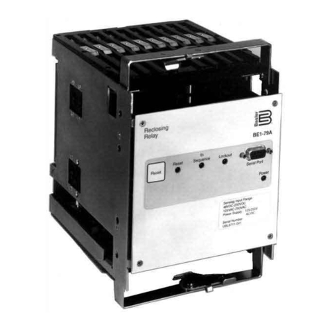
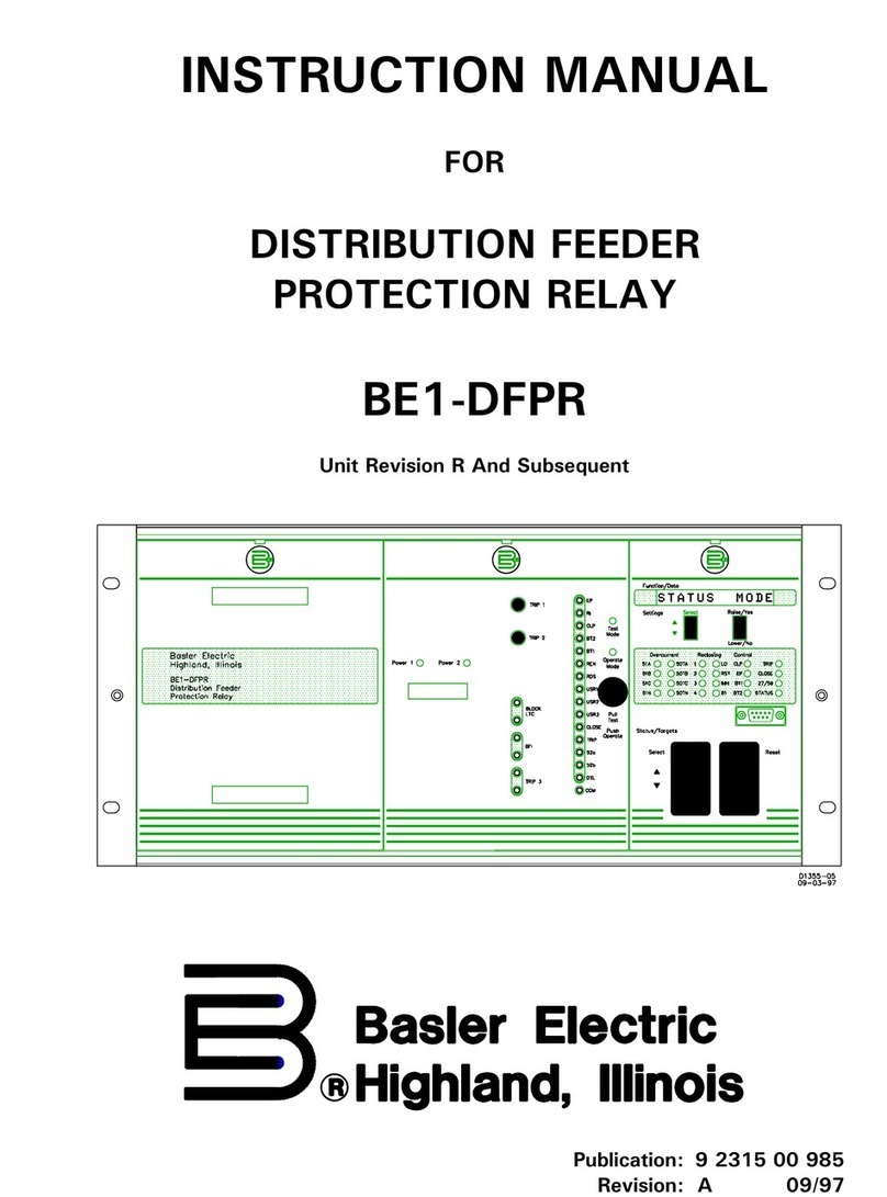
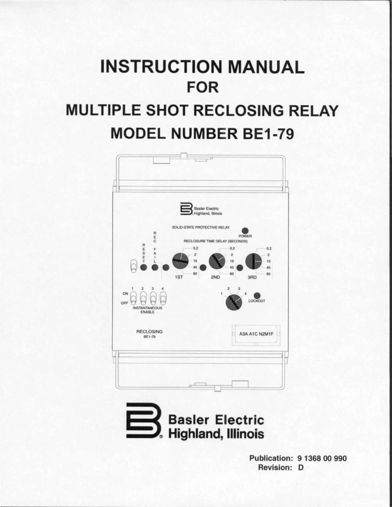
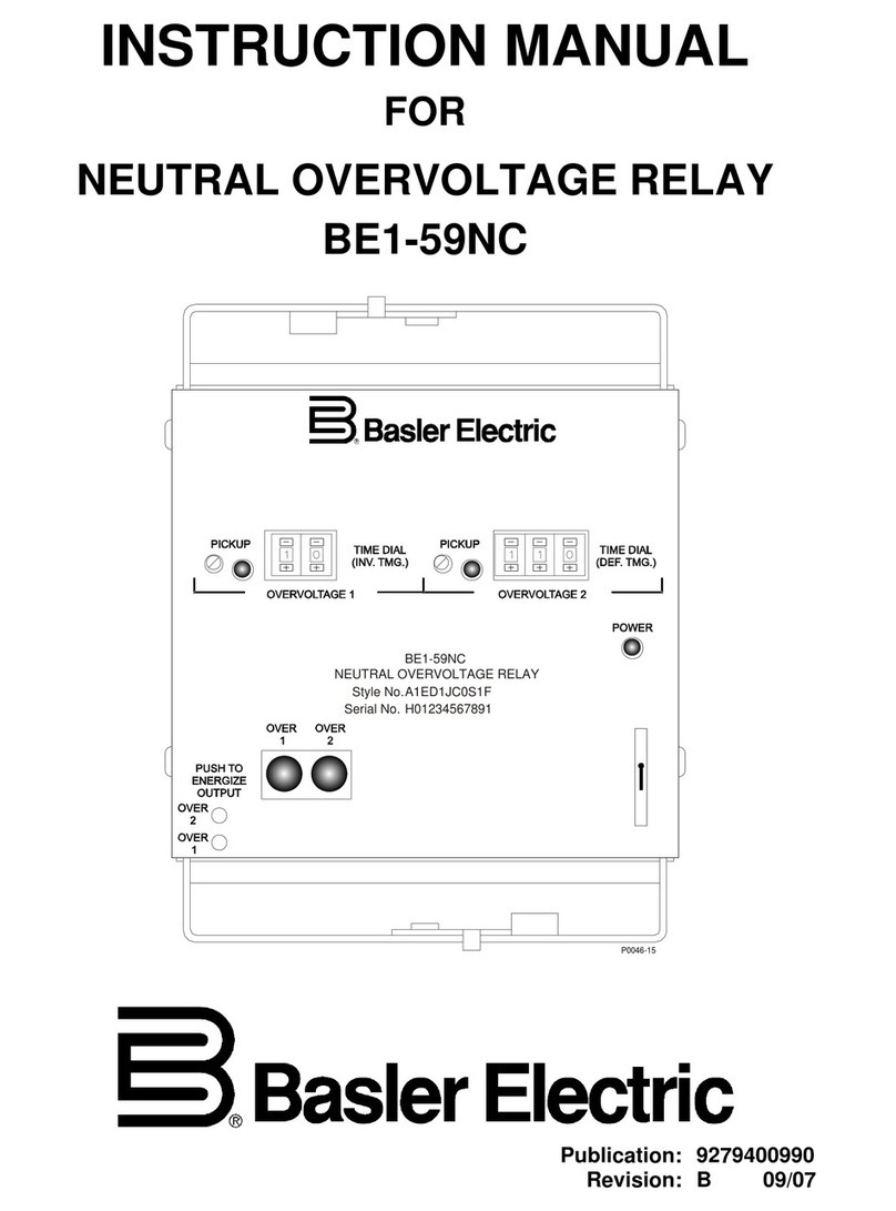
Basler BE1-51C User manual

R
Basler Electric
Hi
g
hland, Illinois
SOLID-STATE PROTECTIVE RELAY
TIME OVERCURRENT
TPUT
RGIZE
H TO
RESET
TARGET
ELEMENTFUNCTION
GCBA
INST 2INST /CLOSE
TIME 1
TAP
TAP
PHASE GROUND
RS-232 PORT
DWN
UP
TMG
TMG
CBA
AB
C
D
EF
G
H
IJ
AB
C
D
EF
G
H
IJ
JIHGFEDCBATAP 11.010.09.08.07.06.05.04.03.02.0HIGH 5.04.54.03.53.02.52.01.51.00.5LOW
POWER
STATUS
FUNC/DATA MODE
NEXT
HIGH LOW
5-12-92
D1147-10
+05647%6+10/#07#.
(14
%1//70+%#6+10518'4%744'06
4'.#;
/1&'.$'%
2WDNKECVKQP
4GXKUKQP %

i
BE1-51C Communications Overcurrent Relay
Version 1.6
Software Revision 3.46
W A R N I N G !
TO AVOID PERSONAL INJURY OR EQUIPMENT
DAMAGE, ONLY QUALIFIED PERSONNEL SHOULD
PERFORM THE PROCEDURES PRESENTED IN THIS
MANUAL.
INTRODUCTION
This manual provides information concerning the operation and installation of:
To accomplish this, the following is provided.
Specifications
Functional description
Mounting information
Operational Test Procedure
A Service Manual, publication 9 2330 00 620, is available on special order as an
aid in troubleshooting and repair.
THIS MANUAL MAY BE USED IN PLACE OF ALL EARLIER EDITIONS. FOR
CHANGE INFORMATION SEE SECTION 8.
REV A B C
ECA 11660 12632 14742

ii
CONFIDENTIAL INFORMATION
OF BASLER ELECTRIC COMPANY, HIGHLAND, IL. IT IS LOANED FOR
CONFIDENTIAL USE, SUBJECT TO RETURN ON REQUEST, AND WITH THE
MUTUAL UNDERSTANDING THAT IT WILL NOT BE USED IN ANY MANNER
DETRIMENTAL TO THE INTEREST OF BASLER ELECTRIC COMPANY.
First Printing: August 1990
Printed in USA
November 1994
It is not the intention of this manual to cover all details and variations
in equipment, nor does this manual provide data for every possible
contingency regarding installation or operation. The availability and
design of all features and options are subject to modification without
notice. Should further information be required, contact Basler
Electric Company, Highland, Illinois.
BASLER ELECTRIC, BOX 269 HIGHLAND, IL 62249 USA
PHONE 618-654-2341 FAX 618-654-2351

iii
contents
Section 1 GENERAL INFORMATION 1-1
Description ........................................1-1
Application ........................................1-1
Time Overcurrent Function ............................1-1
Pickup .........................................1-1
Timing .........................................1-1
Trip and Reset ..................................1-2
Instantaneous Overcurrent Options .....................1-2
Command Actuated Close (Outputs) ....................1-2
Neutral Trip Selectivity ...............................1-2
Breaker Failure .....................................1-3
Communications Option ..............................1-4
Ports ..........................................1-4
System Considerations ............................1-4
Style Number ......................................1-5
Style Number Identification Chart .......................1-6
Specifications ......................................1-7
Time Overcurrent Curves .............................1-9
Section 2 CONTROLS and INDICATORS 2-1
Section 3 FUNCTIONAL DESCRIPTION 3-1
General ...........................................3-1
Current Sensing ....................................3-1
Power Supply ......................................3-1
General ........................................3-1
Loss-of-Power Sensing ...........................3-3
Analog-to-Digital (A/D) Converter .......................3-3
Internal Microcomputer ...............................3-3
Time Overcurrent Calculations ......................3-3
High/Low Range Register ..........................3-3
Watchdog Circuitry ...............................3-3
Outputs ...........................................3-3
General ........................................3-3
Relay Disabled Output ............................3-4
Instantaneous and Command Close Options ...........3-4
Target Indicators ....................................3-4
Communications Option ..............................3-4
Section 4 OPERATION BY FRONT PANEL 4-1
General ...........................................4-1
Configuration Mode .................................4-1
Defined ........................................4-1
Entering the Configuration Mode ....................4-1
Stepping Through the Read/Write Registers ...........4-1
Loading the Read/Write Registers ...................4-3
Setting the Baud Rate ............................4-3

iv
CONTENTS - Continued
Section 4 OPERATION BY FRONT PANEL (continued) 4-1
Setting the Time Dial .............................4-3
Setting Tap Calibration ............................4-3
Setting Instantaneous Overcurrent Pickup .............4-3
Selecting the Time Overcurrent Characteristic ..........4-4
Selecting the CT Ratios ...........................4-4
Current Sensing Range ...........................4-4
Demand Period .................................4-4
Data Mode ........................................4-4
Defined ........................................4-4
Entering the Data Mode ...........................4-5
Automatic Scrolling ...............................4-5
Instrumentation Display ...........................4-5
Error Code Display ...............................4-6
Setting the Relay (Example) ...........................4-6
Example Defined ................................4-6
Calculating the Settings ...........................4-6
Entering the Settings .............................4-7
Section 5 OPERATION BY COMPUTER 5-1
Equipment and Procedures ...........................5-1
General ........................................5-1
Port Converter ..................................5-1
Baud Rate .........................................5-1
The Registers ......................................5-1
General ........................................5-1
The Secure Registers .............................5-1
Register Overview ...............................5-2
Instrumentation Registers ..........................5-2
Port Wiring ........................................5-2
Section 6 INSTALLATION AND TESTING 6-1
General ...........................................6-1
Relay Operating Precautions ..........................6-1
Dielectric Test ......................................6-1
Mounting ..........................................6-1
Connections .......................................6-2
Verification Testing ..................................6-2
General ........................................6-2
Scope .........................................6-2
Operational Test .................................6-3
Equipment Required ..............................6-3
Preliminary Steps ................................6-3
Time Overcurrent Pickup Test ......................6-4
Timing Test .....................................6-5
Instantaneous Overcurrent Pickup Test ...............6-6
Communications Test ................................6-7
General Verification ..............................6-7
Command Actuated Close .........................6-7
v
CONTENTS - Continued
Section 7 MAINTENANCE 7-1
General ...........................................7-1
In-House Repair ....................................7-1
Storage ...........................................7-1
Troubleshooting ....................................7-2
Built-In-Test ....................................7-2
Batch Programs .................................7-2
Timekeeping .......................................7-2
Section 8 MANUAL CHANGE INFORMATION 8-1
REFERENCES On Inside Rear Cover

1-1
SECTION 1
)'0'4#.+0(14/#6+10
DESCRIPTION
The BE1-51C Communications Overcurrent Relay is a microprocessor based time overcurrent relay
designedforeasyincorporationintoacomputermanaged powersystem. Itisavailablein anumberofstyles
to supply single-phase, two-phase-with-neutral, three-phase, and three-phase-with-neutral protection for
power systems.
The relay provides for the incorporation of an optional communications board to interface with external
devices via (typically) a systems-managing computer. The communications interface, when fully
implemented, allows remote monitoring of circuit and breaker information in real time, the transmission of
historical data, and remote control of operating parameters.
APPLICATION
The BE1-51C relay is utility grade, and may be used for the protection of medium voltage electrical power
systems. It is designed to monitor the outputs of standard (5 A secondary) current transformers and, when
tripped, to close an output contact that may be used to trip a breaker.
The relay requires power for its internal circuits. A number of ac and dc supply voltage options are available
for this purpose that match the usual ac or dc power used for tripping the circuit breaker.
TIME OVERCURRENT FUNCTION
Pickup
A coarse incremental adjustment of overcurrent pickup is provided by front panel rotary switches. One
switch simultaneously sets the pickup point for all the monitored phases. If neutral is also monitored, a
second rotary switch independently sets the neutral overcurrent pickup point.
Afine incrementaladjustment that provides99 intermediatepickup points betweenadjacent positions of the
rotary switches is provided by entering data into the memory of the internal microcomputer.
Timing
A time delay is initiated when a pickup point is exceeded. When the current drops below pickup, the timing
circuit is reset immediately. The amount of delay required before trip is a function of the overcurrent
magnitude, the selected time curve, and the time dial setting.
One of eight time overcurrent characteristics may be selected for the monitored phases. These
characteristicsaregraphically illustratedin Figures1-2through 1-9. Ifneutralcurrentis monitored,its timing
characteristic is independently selected. Selection of the timing characteristics is made at the front panel
or via one of the two communications links.
Aftera characteristic is selected, itis adjusted to specific requirementsby determining theappropriate TIME
DIAL number. (These are the numbers in a vertical row along the righthandmargins of Figures 1-2 through
1-9.) The TIME DIAL number (0 to 99) selects one of the 100 characteristic curves available for each
characteristic type. (Only 14 ofthe 100 curves in the computer memory are shown on each graph because
of space limitations.)

BE1-51C General Information
1-2
The selected TIME DIAL number is entered into the relay memory, again using either the front-panel data
entry controls, or one of the two communications links. The available timing characteristics include one set
of definite time curves, and seven different types of inverse time curves.
Trip and Reset
When the monitored current exceeds the overcurrent pickup point, the TMG LED illuminates and timing
begins. The timing process continues until the interval calculated by the selected time overcurrent
characteristic is completed (thereby tripping the associated output and target indicators), oruntil the sensed
overcurrent drops below the pickup setting (which causes the timer to reset). In either case (trip or reset),
the timing process is terminated. The TMG LED remains on after trip as an indication of contact closure,
or extinguishes at reset.
Although a tripped BE1-51C relay resets immediately when the monitored current drops below the pickup
setting, the target indicators remain tripped until manually reset at the front panel. (Power is required to
reset the targets.)
INSTANTANEOUS OVERCURRENT OPTIONS
Two instantaneous overcurrent outputs can be incorporated. The pickup point of each is adjustable from
0.5 times to 20 times the time overcurrent TAP setting. When the sensed input current exceeds an
instantaneous overcurrent pickup setting, the associated instantaneous output relay is energized. Also a
target indicator is set to show that an instantaneous output was tripped. (On multi-phase relays, additional
indicators denote the phase or neutral element which initiated the timing.)
Thedesiredinstantaneousovercurrentpickupvaluesforphaseand forneutralareenteredvia thedataentry
controls at the front panel. (This can also be done remotely by the data link if the communications option
is present.)
COMMAND ACTUATED CLOSE (OUTPUTS)
Command actuated close is available on all outputs at version 1.6 and subsequent.
When two independent instantaneous outputs are incorporated, the INST2 can be programmed to serve
instead as an output under the control of the (remote) system computer. An enabling requirement for
computer authorized closure is that the breaker be open (i.e., the 52b contact is detected closed). After a
closure is effected by the computer, the output contact stays closed until the breaker recloses (52b opens)
or one second has elapsed.
Additionally, the timed and INST1 can be closed from computer control. This close time is limited to one
second.
Note that a computer actuated output cannot be employed unless the Communications Board has been
INSTalled in the relay (Option 2-C). Also, if a contact is programmed to serve the Command Close
application, it cannot simultaneously serve as the INST2 trip output.
NEUTRAL TRIP SELECTIVITY
This standard feature of the BE1-51C allows the neutral element to be enabled or disabled on the timed and
INST1 output. Alternatively, their functions can be shifted to the INST 2 output relay (functions are shifted
when the affected output bit is set to a 1). This information is in register 65.

BE1-51C General Information
1-3
neutral flag xxxx xxxx
|||| ||||--neutral function active
|||| |||----50g function active
|||| ||-----51g function active
|||| |-------affected output (0 = normal = TIMED and INST1, 1 = INST2)
Following are examples of the internal flags. When the setting is handled from the front panel, these flags
are not available to the user. When the setting is from the computer, these flags are needed.
Partial list of examples (function 07 is identical to units version 1.5 and previous).
FLAG DESCRIPTION
0000 xxx0 Neutral function selectivity completely disabled (same functionality as 07h)
0000 0011=03h Neutral function enabled for 50 element
Neutral function disabled for 51 element
Functions incorporated into existing output relays (51, INST1)
0000 0101=05h Neutral function enabled for 51 element
Neutral function disabled for 50 element
Functions incorporated into existing output relays (51, INST1)
0000 0111=07h 50g and 51g both enabled
Neutral functions incorporated with phase functions (51, INST1)
This is how BE1-51C/SCOR version 1.5 and previous functioned.
0000 1011=0bh Neutral function disabled for 51 element
Neutral function enabled for 50 element
Functions removed from existing output relays and grouped into INST2
output relay
0000 1101=0dh Neutral function enabled for 51 element
Neutral function disabled for 50 element
Functions removed from existing output relays and grouped into INST2
output relay
0000 1111=0fh Neutral function enabled for 51 element
Neutral function enabled for 50 element
Functions removed from existing output relays and grouped into INST2
output relay
BREAKER FAILURE
This standard feature invokes a breaker failure function within the relay. If enabled (reg 68=01) the function
occurs as follows.
The breaker failure function involves a 1 second timer. When a trip occurs, the timer starts. At timeout, two
checks are made: one, that the breaker properly changed state, and two, that the current is below approx
10% of the tap value. If the results of either check is not correct, then a breaker failure has occurred.

BE1-51C General Information
1-4
The result of a breaker failure is an event in the event log. The event contains the timestamp and the
breaker status (register 68). A sample of the breaker status in register 68 follows.
Reg 68 Breaker Status (This is a read/write register.)
xxxx xxxx
|||| ||||--spare
|||| |||---spare
|||| ||----spare
|||| |-----timeout without breaker change of state
||||-------phase a > 0.1 x tap
|||--------phase b > 0.1 x tap
||---------phase c > 0.1 x tap
|----------phase n > 0.1 x tap
COMMUNICATIONS OPTION
Ports
The communications interface (a plug-in board, Option 2-C) supports an RS-232 port on the front panel and
an RS-485 port on the back of the relay case. (These are also known by the designations EIA-232 and EIA-
485.) Both ports have equal access to the relay registers. When connection is made to the RS-232 port,
the RS-485 port is disabled.
The RS-232 port is for relatively shortrange communication (under 50 feet). Its intended purposes are local
testing and maintenance. (For RS-232 wiring connections, see Section 5.)
The RS-485 provides for intercommunication between the relay and a system-control computer over a
shielded twisted pair at distances of up to 4000 feet. (For RS-485 wiring connections, see Section 5.)
System Considerations
The data and settings capability of the communications link includes:
Real-time data for amperes (each phase and neutral), and amperes demand (each phase). The
monitored line current is expressed in primary quantities:
IMONITORED = (IRELAY)(system CT ratio).
Relay status (normal/timing/tripped), and breaker position (open/closed).
Event record, with amperes prior to trip, timestamp, element which caused trip, and targets. The last
20 events are stored in the relay non-volatile memory.
MIN/MAX log, which contains the minimum and maximum values for polyphase current and polyphase
demand current which have occurred since last cleared.
Selected setting data for phase and neutral, including time overcurrent function and curve selected,
pickup settings, and primary current transformer ratio.
Whichever port is used, all communications must be initiated by the computer. When the computer
addresses the relay, all of the relay storage registers may be read by the computer.

BE1-51C General Information
1-5
STYLE NUMBER
Thestyle numberof the relaydetermines the features tobe included (orordered) fora particular application.
Each available option is represented by a character as shown in the Style Number Identification Chart
(Figure 1-1).
Suppose, for example, it was decided that three-phase-with-neutral monitoring would be best for an
application. Then the first character of the style number would be H.
The second character of the style number depends upon the range required for overcurrent pickup. For
example, Sensing Input Range 1 would have a range of 2.0 to 11.0 A for each phase, and a range of 0.5
to 5.0 A for the neutral current.
Normally open (NO) output contacts for tripping the breaker are standard, so output Option E is the third
character.
The fourth and fifth characters are Z5, representing switch selectable timing standard on the BE1-51C
relay. This feature allows the timing to be selected from any of the eight overcurrent timing functions
illustrated in Figures 1-2 through 1-9.
The sixth character represents the most convenient source of operating power for the relay. If it is J, the
internal power for the relay is derived from an external source of 125 Vdc or 120 Vac (nominal).
Since only one target configuration is offered, the seventh character is B. Note that all of the FUNCTION
targetsare current operated. Current operatedtargets are advantageousbecause they confirm that current
did flow in the output circuit as the result of a trip. (Since the ELEMENT targets are not associated with any
output contacts, they are internally operated.)
If one instantaneous overcurrent element is needed, the eighth character of the style number is 1; if two, the
eighth character is 2. Alternatively, if the eighth character is 2 the second instantaneous overcurrent output
contact can be programmed to function as an output that is externally controlled by computer.
Theninthcharacter mustbe Cto specifythe communicationsboard option. Thisallows communicationwith
a remote computer or a local terminal.
The tenth character of the style number is always 0, and the last character always F. (These relays are
always supplied in a draw out case for semi-flush mounting.)

BE1-51C General Information
1-6
Figure 1-1. Style Number Identification Chart

BE1-51C General Information
1-7
I
K
T
BE1-51C SPECIFICATIONS
TheBE1-51Crelayisavailableinsingle-phase,three-phase,two-phase-with-neutral,andthree-phase-with-
neutral configurations, and with the following features and capabilities.
Current Sensing Inputs The unit is designed to operate from the secondary of a standard current
transformer rated at 5 A. The maximum continuous current rating for each
input is five times tap or 20 A, whichever is less.
The one-second current rating for each input is 50 times tap or 500 A,
whichever is less. Ratings at less than one second are calculated as:
where
K = (500 A or 50 times TAP)2
T = Time that current flows (in seconds)
Current Sensing Burden Less than 0.1 ohm.
Frequency (nominal) 60 Hz.
Time Overcurrent
Pickup Ranges Two ranges are available: HIGH (2-11 A), and LOW (0.5-5 A). Range is
independently specified for phase and neutral by the second digit of the
Style Number. The TAP range plate(s) on the front panel indicate which
range (HIGH or LOW) is specified.
Pickup Adjustment Incrementally adjustable over the selected range by a front-panel (TAP)
selector switch (coarse), and by numerical data entered into the Tap Cal
register (fine).
Pickup Setting Accuracy The accuracy of the pickup setting is ±2% of the programmed setting over
the full specified range of the relay at 60 Hz.
Pickup Repeatability Within 2%.
Dropout Ratio Better than 80% of the established pickup level within 50 milliseconds.
Instantaneous Overcurrent
Pickup Range 0.5 to 20 times the value of the time overcurrent pickup setting.
Pickup Setting Accuracy The accuracy of the instantaneous pickup setting is ±2% of the
programmed setting over the full specified range of the relay at 60 Hz.
Pickup Repeatability Within 2%.
Dropout Ratio Better than 80% of the established pickup level within 50 milliseconds.

BE1-51C General Information
1-8
Overcurrent Timing The relay incorporates all of the time overcurrent characteristics shown in
Characteristics Figures 1-2 through 1-9. Selection of a specific timing characteristic is
accomplished by programmed INSTructions. Separate selections can be
made for phase current and for neutral current.
Time Delay Accuracy The time overcurrent delay will be within 5% or 40 milliseconds (whichever
isgreater) ofthe characteristic curves shownin Figures 1-2 through 1-9for
any combination of TIME DIAL and pickup setting at 25C. The time delay
will not vary more than ±5% over the temperature range of -40to 70C (-
40to 158F).
Instrumentation Feature Provision is made to monitor various input parameters (e.g., primary
current) on a real time basis. Accuracy is within ±2%. Range is from 0.1
X TAP (at the low end) to 1.5 X pickup (at the high end).
Communications Option Includes an RS-232 port on the front panel for testing and local
programming,andanRS-485port atrearofunitfor operationbyasystems
computer at distances up to 4000 feet using baud rates up to 19,200.
PowerSupply Powerfor theinternal circuitrymaybederived fromacor dcexternal power
sources as indicated in Table 1-1.
Table 1-1. Power Supplies
Type Nominal
Input Range Input
Voltage Range
Burden At
Nominal
(Maximum)
K 48 Vdc 24 to 60 Vdc 7.0 W
J 125 Vdc
120 Vac 62 to 150 Vdc
90 to 132 Vac 8.0 W
19.0 VA
Target Indicators
For Single-Phase Units Current-operated targets are furnished for each of the tripping outputs
included within the relay (e.g., TIME and instantaneous overcurrent
functions). To trip, a current-operated target requires a minimum of 0.2 A
in the output circuit of its associated output contact. This confirms that
current has flowed through the relay output contacts and the external trip
circuit.
For Multi-Phase Units Includes the above plus an internally-operated target for each phase
element (A, B, C, and/or neutral) which may initiate a trip.
Outputs Output contacts are rated as follows:
Resistive
120/240 Vac Make 30 A for 0.2 seconds, carry 7 A continuously,
break 7 A.
250 Vdc Make and carry 30 A for 0.2 seconds, carry 7 A
continuously, break 0.3 A.
Outputs - Continued 500 Vdc Make and carry 15 A for 0.2 seconds, carry 7 A
continuously, break 0.1 A.

BE1-51C General Information
1-9
inductive
120/240 Vac, Make and break 0.3 A (L/R=0.04).
125/250 Vdc
Shock In standard tests the relay has withstood 15 g in each of three mutually
perpendicular axes without structural damage or degradation of
performance.
Vibration In standard tests the relay has withstood 2 g in each of three mutually
perpendicular axes, swept over the range of 10 to 500 Hz for a total of six
sweeps,15minuteseachsweep,withoutstructuraldamageordegradation
of performance.
Isolation 1000 Vac at 60 hertz for one minute may be applied across output terminal
pairs in accordance with IEC 255-5 and ANSI/IEEE C37.90-1989
(Dielectric Test). Maximum applied voltage must be no greater than 300
volts where MOV suppressors are used. Terminals 11 and 12 have MOV
suppressors installed between terminals and ground. Terminals 3 and 4
have one MOV suppressor installed between the terminals. All terminals
have decoupling capacitors installed between terminals and ground.
According, a leakage current of approximately 2.0 milliamperes per
terminal is to be expected when high potting at 1000 Vac, 60 hertz. 1500
Vacat 60hertz forone minute maybe appliedacrosscurrent sensinginput
terminals, between circuit groups, and between circuit groups and chassis
ground in accordance with IEC 255-5 and ANSI/IEEE C37.90-1989
(Dielectric Test).
Surge Withstand Capability Qualified to ANSI/IEEE C37.90.1-1989
Standard Surge Withstand
Capability Tests for Protective Relays and Relay Systems.
Impulse Test Qualified to IEC 255.
Radio Frequency Interference Maintains proper operation when tested for interference in accordance
with
(RFI) IEEE C37.90.2-1989,
Trial-Use Standard Withstand Capability of Relay
Systems to Radiated Electromagnetic Interference.
Temperature
Operating -40to 70C (-40to 158F).
Storage -65to 100C (-85to 212F).
Weight 14.8 pounds net.
Case Size S1. (Dimensions are given in Figure 6-1.)
Certification UL pending.
TIME OVERCURRENT CHARACTERISTIC CURVES
Figures1-2 through1-9 illustratethe characteristic curvesthat areprogrammedinto thenonvolatile memory
of this relay. A drawing number is given under each caption. Use this number to order a full-size (10 inch
x 12 inch) Characteristic Curve graph.

BE1-51C General Information
1-10
Figure 1-2. Timing Option B1,
Short Inverse (99-1250) Figure 1-3. Timing Option B2,
Long Inverse (99-1251)

BE1-51C General Information
1-11
Figure 1-4. Timing Option B3,
Definite Time (99-1252) Figure 1-5. Timing Option B4,
Moderate Inverse (99-1253)

BE1-51C General Information
1-12
Figure 1-6. Timing Option B5,
Inverse (99-1254) Figure 1-7. Timing Option B6,
Very Inverse (99-1255)

BE1-51C General Information
1-13
Figure 1-8. Timing Option B7,
Extremely Inverse (99-1256) Figure 1-9. Timing Option B8,
I
2
T (99-1257)

2-1
SECTION 2
%10641.5#0&+0&+%#6145
Figure 2-1 shows the front panel of the BE1-51C relay with all the options installed. Each control and
indicator is assigned a locator letter which is described in Table 2-1.
Table 2-1. BE1-51C Controls and Indicators
Locator Control or Indicator Function
A PHASE TAP A ten-position switch that provides an incremental
adjustment of the current pickup point for all of the
phases (simultaneously). The switch positions are
defined for both HIGH and LOW range in a table printed
on the front panel (locator O of Figure 2-1). (Inter-
mediate settings between the switch positions may be
established by the Tap Cal register.)
B PHASE TMG (A, B, C)
Indicators LEDs that lite when the preset overcurrent pickup
phase point for the corresponding phase is exceeded.
C PHASE Range Plate Indicates the range of the phase current inputs of the
phase relay. The range is either HIGH or LOW.
(Reference the TAP value table, locator O.) Note that
the range is actually determined when the relay is
ordered; the setting of this plate is simply for guidance in
interpreting the TAP value table.)
D FUNC/DATA This four-character, seven-segment LED display (with
display right-hand decimal point for each digit) has two
modes of operation: (1) the DATA mode which permits
reading the instrumentation registers, and (2) the
CONFiguration mode that permits reading and writing
into the registers that control operation of the relay.
The instrumentation registers monitor the input current
and the demand current in kiloamperes. A row of dashes
indicates an out-of-range condition. (Dashes along the
bottom of the display indicate that the current is
somewhere below 0.1 X TAP. Dashes along the top
indicate a current above 1-1/2 X pickup.)
A front-panel switch (locator I) can cause the display to
exhibit a particular register of interest in either mode. If
while in the CONFiguration mode neither the UP/DWN
nor the MODE/NEXT switches have been actuated for
one minute, the display will revert to the DATA mode.
(This protects the settings by requiring the deliberate
action of loading to effect a change. In the DATA mode,
however, a specifically selected register can be
displayed indefinitely.) Note that when in the
CONFiguration mode, the relay output are inoperative.
Table of contents
Other Basler Relay manuals

Basler
Basler BE1-27 User manual

Basler
Basler BE1-51/27R User manual

Basler
Basler BE1-700C User manual

Basler
Basler BE1-81O/U User manual

Basler
Basler BE1-59N User manual

Basler
Basler BE1-BPR User manual

Basler
Basler BE1-51B User manual

Basler
Basler BE1-24 User manual

Basler
Basler BE1-32 User manual

Basler
Basler BE1-50BF User manual

Basler
Basler BE1-59N User manual

Basler
Basler BE1-50/51B-225 User manual

Basler
Basler BE1-87G User manual

Basler
Basler BE1-40Q User manual

Basler
Basler BE3-GPR User manual

Basler
Basler BE1-47N User manual

Basler
Basler BE1-25 User manual

Basler
Basler BE1-11g User manual

Basler
Basler BE1-50BF User manual

Basler
Basler BE1-79A User manual