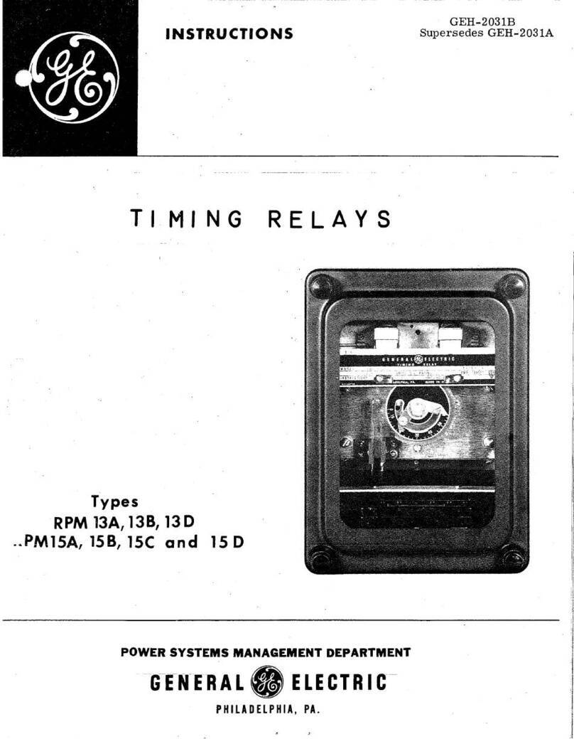
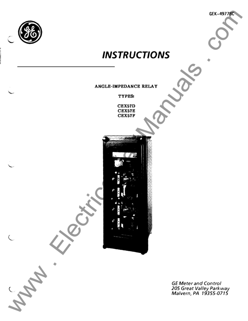
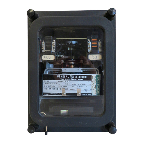
GE CAP15A User manual

INSTRUCTIONS
GEI-12083J
POWER
DIRECTIONAL
RELAYS
Types
(APl
SA
(APlSI
GENERAL
_
ELECTRIC

GEI-12083
TABLE
OF
CONTENTS
APPLICATION
. .
RATINGS
....
12CAPI5A(-)A
12CAP15B(-)A.
CONTACT
RATINGS
..
SHORT
TIME
RATINGS
..
POTENTIAL
COIL
RATINGS.
TARGET
AND
HOLDING
COILS.
OPERATING
CHARACTERISTICS
BURDENS
...
CURRENT
. . . . . . . . .
POTENTIAL
. . . . . . . .
CONSTRUCTION
.......
.
RECEIVING,
HANDLING
AND
STORAGE
PERIODIC
CHECKS
AND
ROUTINE
MAINTENANCE
CONTACT
CLEANING
......
.
POWER
REQUIREMENTS
-
GENERAL·
ELECTRICAL
TESTS
.....
.
DRAWOUT
RELAYS
-
GENERAL.
ACCEPTANCE
TESTS
..
LOCATION
.....
.
MOUNTING
.....
.
CONNECTIONS
. . . .
INSTALLATION
TESTS.
OPERATION
. . . .
ADJUSTMENTS
. . .
CUP
AND
STATOR
..
ACCEPTANCE
TESTS
•.
HOLDING
COILS
. . . .
CONTROL
AND
LEAD-IN
SPRING.
CLUTCH
-
12CAP15B(-)A
.
CLUTCH
-
12CAP15A(-)A
.
SERVICING
-
12CAP15A(-)A.
MECHANICAL
ADJUSTMENTS.
POLARITY
TESTS.
. . . .
PHASE
ANGLE
TESTS
. . .
SERVICING
-
12CAP15B(-)A.
ME
CHAN
I
CAL
ADJ
USTMENTS
.
POLARITY
TESTS.
.
PHASE
ANGLE
TESTS
.
CORE
ADJUSTMENTS
..
PIC
KUP
ADJ
US
TMENT
.
HOLDING
COIL
CHECK.
TARGET
CHECK
...
HI-POTENTIAL
TEST
RENEWAL
PARTS
. . . .
2
Page
3
3
3
3
4
4
4
4
5
5
5
5
5
6
6
6
6
6
6
7
7
7
7
7
8
8
8
9
9
9
9
t)
10
10
10
10
11
11
11
12
12
12
12
12
12
12

GEI-12083
The
Type
CAP15A
and
Type
CAP15B
relays
consist
of
one
three-phase
unit,
with
one
rotor
mounted
on
a
shaft.
The
contact assembly
consists
of
two
electrically
separate
contacts,
one
normally-open
and
one
normally-closed.
The
normally closed contacts
are
held closed,
when
the
relay
is
not energized,
by
means
of
two
spiral
springs
which
also
complete the control
circuit
to the
moving
contacts.
APPLICATION
The
CAP15A
relay
is
a three-phase
induction-cylinder
power
directional
relay.
Its
principal
application
is
to perform the
directional
duties
in
directional
overcurrent scheme.
The
recommended
A-C
external wiring
connection
for
the
Type
CAP15A
relay
are
shown
in Figure 9, connection
A.
I~ith
this
connection the
relay
has
maximum
torque
on
a balanced three-phase condition
when
the
line
current
lags
its
unity
power
factor
po-
sition
by
40
degrees in the
tripping
direction.
On
a zero voltage phase-to-phase
fault
just
beyond
the
relay
terminals,
the relay
has
maximum
torque
when
the
current
laqs
its
unity
power
factor
position
by
70
degrees in the
tripping
direction.
Figure 2 demonstrates the
directional
characteristics
of
the
preferred
connection (60 degree connection).
The
30
degree
and
90
degree connections are
also
shown
in Figure 9,
with the corresponding angle
of
maximum
torque
for
balanced
conditions.
If
the
relay
is
used in
an
application
where
there
is
the
possibility
of a
momentary
reversal
of
power
immediately following the
clearing
of
a
fault,
and
if
the overcurrent
relay
contacts
have
closed,
it
is
necessary to provide
directional
control to prevent
false
tripping.
In the case of time-delay
overcurrent
relays,
this
may
be
done
by
allowing the overcurrent relays to operate only
if
the
fault
is
in the pro-
tected
direction.
If
the overcurrent
relay
is
instantaneous in
operation,
discriminating control
may
be
obtained
by
using the right-hand contact to
contrr~
a
Type
HGA
auxiliary
relay as
shown
in Figure 3.
If
both
directional
contacts are used
and
if
a
momentary
reversal of
power
immediately following the
clearing
of a
fault
is
not
possible,
it
is
still
advisable to use
some
method
of
directional
control.
This
is
evident because
when
a
fault
is
removed,
sufficient
energy will
be
stored
in the
deflected
contact
to
caus~
rebound to the
other
contact.
If
only
one
contact
is
being used, the
stored
energy in the
other
contact
may
be
substantially
eliminated
by
reversing the contact
barrel
and
its
sleeve in the contact hol-
der thereby using the
back
end
'as a
solid
stop.
This
is
done
by
loosening the screw
that
locks the
barrier
in
place,
remove
the barrel
and
sleeve,
unscrew toe sleeve
from
the
Barrel,
insert
the sleeve
into
the con-
tact
support
from
the
inside
and
screw the
barrel
into
it
from
the outside with the contact pointing
cut.
When
the stop
is
located
where
desired,
lock in
position
by
tightening
the screw.
It
has
been
found ad-
visable
to
remove
the corresponding
moving
contact
finger
as
well.
The
Ty~o
CAP15B
relay
is
a general purpose reverse
power
relay.
This relay measures
true
watts
and
is
practically
unaffected
by
the
reactive
component
of
power. Because
this
relay
is
a high speed
relay,
it
should always
be
used with a
suitable
timing
relay
in order to prevent undesired operations during system
disturbances
which
cause
momentary
power
reversals.
An
application
of
the
CAP15B
is
shown
in Figure 13.
RATINGS
12CAP15A(-)A
The
12CAP15A(-)A
relays are
available
at
voltage
ratings
of 115, 130,
208
and
230
volts.
The
current
circ~its
are continuously
rated
at
five
amperes with frequencies
available
at
25, 35,
50
and
60
hertz.
The
targets
and
holding
coils
are
available
at
0.2
and
1.0
amperes d-c
rating.
12CAP15B(-)A
The
12CAP15B(-)A
relays are
available
at
voltage
ratings
of
115, 208,
and
230
volts.
The
current
circuits
are continuously
rated
at
five
amperes with frequencies
available
at
25,
50
and
60
hertz.
The
targets
and
holding
coils
are
available
at
0.2
and
1.0
ampere
d-c
rating.
These
instructions
do
not
purport
to
cover
all
details
or
variations
in
equipment
nor
to
provide
for
every
possible
contingency
to
be
met'in
connection
with
installation,
operation
or
maintenance.
Should
further
information
be
desired
or
should
particular
problems
arise
which
are
not
covered
sufficiently
for
the
purchaser's
purposes,
the
matter
should
be
referred
to
the
General
Electric
Company.
To
the
extent
required
the
products
described
herein
meet
applicable
ANSI,
IEEE
and
NEMA
standards;
but
no
such
assurance
is
given
with
respect
to
local
codes
and
ordinances
because
they
vary
greatly.
3

GEI-12083
CONTACT
RATINGS
The
contacts
of
both types
of
CAP
relays
can
momentarily carry
30
amperes
for
voltages not exceeding
250
volts.
However,
the contacts
do
not
have
an
interruptin~
rating.
Therefore, the
trip
circuit
must
be
opened
by
some
other
means.
Each
stationary
contact,
Figure 6,
is
mounted
on
a
flat
spiral
spring
(F)
backed
up
by
a
thin
dia-
phragm
(Cl.
These
are both
mounted
in a
slightly
inclined tube (A). A
stainless
steel
ball
(B)
is
placed
into
the tube before the diaphragm
is
assembled.
\~hen
the
moving
contact
hits
the
stationary
contact,
the energy of the former
is
imparted to the
latter
and
thence to the
ball,
which
is
free
to
roll
up
the
inclined
tube. Thus, the
moving
contacts
come
to
rest
with
substantially
no
rebound or
vibration.
To
change the
stationary
contact brush,
remove
the contact barrel
and
sleeve as a complete
unit
after
loosening the screw
at
the
front
of the contact block.
Unscrew
the
cap
(E).
The
contact brush
can
then
be
removed.
SHORT
TIME
RATINGS
The
current
coils
of
all
the
CAP
relays
have
a
one
second
rating
of
220
amperes.
To
determine the
current
that
can
be
applied for
more
than
one
second, the following f
ltion
can
be
used.
12t = K K=
2202
= 48400/1 second
I =
IT
Applied
current
t
Time
in seconds
POTENTIAL
COIL
RATINGS
The
potential
coils
of
all
the
CAP
relays are continuously rated
at
their
nameplate voltage value.
TARGET
AND
HOLDING
COILS
The
rating
for the
target
and
holding coil are given in the following
table
I
TABLE
I
AMPERES
A.C.
OR
D.C.
FUNCTION
1
AMP
0.2
AMP
Coil
Resistance 0.25
ohm
D.C.
7.0
ohm
D.C.
Tri
ppi
ng
Duty
30
5
Carry Continuous 1.25* 0.5
*Determined
by
the control spring
rating.
The
0.2
ampere
coil
is
for use with
trip
coils
that
operate
on
currents
ranging
from
0.2
ampere
to
one
ampere
at
the
minimum
control voltage.
If
this
coil
is
used with
trip
coils
that
take
one
ampere
or
more,
there
is
a
possibility
that
the seven
ohms
resistance
will reduce the
tripping
current
to a
low
value
and
then the breaker will not
trip.
This coil
can
safely
carry
tripping
currents
as high as
five
amperes.
The
one
ampere
coil should
be
used
with
trip
coils
provided the
tripping
current
does
not exceed
30
amperes
at
the
maximum
voltage.
If
the
tripping
current
exceeds
30
amperes,
an
auxiliary
relay
must
be
used
to control the
trip-coil
circuit.
It
must
be
connected in such a
manner
that
the
tripping
current
does
not pass through the contacts
or
the
target
and
holdinq coil
of
the
protective
relay.
When
it
is
desirable
to adopt
one
type of relay as standard to
be
used
anywhere
on
a system, relays
with the
one
ampere
coil should
be
chosen. These relays should
also
be
used
when
it
is
impossible to
obtain
trip
coil
data,
but
attention
is
called
to the
fact
that
the
tar~et
may
not operate
if
used with
trip
coils
taking
less
than
one
ampere.
4

G~I-12083
OPERATING
CHARACTERISTICS
The
phase angle
and
time
characteristics
of
the
60
cycle
relay
are
shown
in Figures
1,
1A
and
2 with
the
recommended
connections.
BURDENS
CURRENT
The
burden
imposed
by
each
current
coil
at
five amperes
is
given in the
table
below.
With
standard
connections,
one
of the three
current
transformers supplies
two
current
coils
in
series
so
that
the burden
on
that
transformer will
be
twice the
amount
given below.
The
other
two
current
transformers will each
supply
one
current
coil
and
will
have
a burden
as
given in the following
table:
TYPE
CAP15A
Frequency Volt
Amps
~Iatts
P.
F.
60
0.40 0.20 0.50
50
0.35 0.20 0.57
25
0.60 0.55 0.92
TYPE
CAP15B
60
3.6
1.8
0.50
50
3.2 1.8 0.57
25
2.6 2.4 0.92
POTENTIAL
The
potential
burdens per
relay
circuit
(studs 13-14, 15-16, 17-18
and
19-20)
are
listed
in the
following
table.
Relay Frequency Volt
Amps
Watts
P.
F.
CAP15A
60
5.3 1.60 0.30
50
6.2 2.15 0.35
25
3.5 1.85 0.53
CAP15B
60
4.7 2.35 0.50
50
5.8 2.89 0.50
25
3.5
1.85 0.53
CONSTRUCTION
The
stator
has
eight
laminated magnetic poles
projecting
inward
and
arranged symmetrically around a
central
magnetic core.
The
poles are
fitted
with
current
and
potential
coils.
In
the annular
air
gap
between the
coils
and
the
central
core,
is
the
cylindrical
part
of
the
cup-like
aluminum
rotor,
which
turns
freely
in the
air
gap.
The
central
core
is
fixed
to
the
stator
frame
and
the
aluminum
cup
rotates
carrying the
moving
contacts.
This construction provides a higher torque
and
a lower
rotor
inertia
than the induction disk construc-
tion,
and
makes
the
relay
faster
and
more
sensitive
than the disk-type
relays.
The
CAP
relays are contained in
an
S2
drawout case providing a
means
to
remove
the
relay
from
the
circuitry
without disconnecting
any
wiring.
The
outline
and
panel
drilling
diagram
is
shown
in Figure 15.
5

GEI-12083
RECEIVING,
HANDLING
AND
STORAGE
These
relays,
when
not included
as
a
part
of a control panel, will
be
shipped in cartons designed to
protect
them
against
damage.
Immediately
upon
receipt
of a
relay,
examine
it
for
any
damage
sustained in
transit.
If
injury or
damage
resulting
from
rough
handling
is
evident,
file
a
damage
claim
at
once
with
the
transportation
company
and
promptly notify the nearest General
Electric
Apparatus Sales Office.
Reasonable care should
be
exercised in unpacking the relay in order
that
none
of the
parts
are injured
or the adjustments disturbed.
If
the relays are not to
be
installed
immediately, they should
be
stored in
their
original cartons
in a place
that
is
free
from
moisture, dust
and
metallic
chips. Foreign matter
collected
on
the outside
of the case
may
find
its
way
inside
when
the cover
is
removed
and
cause trouble in the operation
of
the
relay.
PERIODIC
CHECKS
AND
ROUTINE
MAINTENANCE
In
view
of the
vital
role
of
protective
relays in the operation of a
power
system,
it
is
important
that
a periodic
test
program
be
followed.
It
is
recognized
that
the
interval
between
periodic checks will
vary depending
upon
environment, type of relay
and
the
user's
experience with periodic
testing.
Until the
user
has
accumulated
enough
experience to
select
the
test
interval
best
suited
to his individual require-
ments,
it
is
suggested
that
the points
listed
under
INSTALLATION
PROCEDURE
be
checked
at
an
interval of
from
one
to
two
years.
CONTACT
CLEANING
For
cleaning relay
contacts,
a
flexible
burnishing tool should
be
used. This
consists
of a
flexible
strip
of metal with
an
etched-roughened surface resembling in
effect
a superfine
file.
The
polishing action
is
so
delicate
that
no
scratches are
left,
yet
it
will clean
off
any
corrosion thoroughly
and
rapidly.
Its
flexibility
insures the cleaning of the actual points of contact.
Do
not use knives,
files,
abrasive paper
or cloth of
any
kind to clean relay contacts.
POWER
REQUIREMENTS
-
GENERAL
All
alternating
current operated devices are
affected
by
frequency. Since non-sinusoidal
waveforms
can
be
analyzed as a fundamental frequency plus harmonics of the fundamental frequency,
it
follows
that
alternating
current devices
(relays)
will
be
affected
by
the applied
waveform.
Therefore, in order to properly
test
alternating
current relays
it
is
essential
to use a sine
wave
of current and/or voltage.
The
purity
of the
sine
wave
(i.e.,
its
freedom
from
harmonics) cannot
be
ex-
pressed as a
finite
number
for
any
particular
relay;
however,
any
relay using tuned
circuits,
R-L
or
RC
networks, or
saturating
electromagnets (such as time-overcurrent relays)
would
be
essentially
affected
by
non-sinusoidal
wave
forms.
Similarly,
relays requiring d-ccontrol
power
should
be
tested
usingd-c
and
not
full
wave
rectified
power.
Unless the
rectified
supply
is
well
filtered,
many
relays will not operate properly
due
to the
dips in the
rectified
power.
Zener diodes, for example.
can
turn
off
during these dips.
As
a general
rule,
the d-c source should not contain
more
than 5 percent
ripple.
ELECTRICAL
TESTS
DRAWOUT
RELAYS
GENERAL
Since
all
drawout relays in service operate in
their
cases,it
is
recommended
that
they
be
tested
in
their
cases or
an
equivalent
steel
case.
In
this
way
any
magnetic
effects
of the enclosure will
be
ac-
curately duplicated during
testing.
A relay
may
be
tested
without
removing
it
from
the panel
by
using a
12XLA13A
test
plug. This plug
makes
connections only with the relay
and
does
not
disturb
any
shorting
bars in the cases.
Of
course, the
12XLA12A
test
plug
may
also
be
used.
Although
this
test
plug allows
greater
testing
flexibility,
it
also requires C T shorting jumpers
and
the exercise of
greater
care since
connections are
made
to both the relay
and
the external
circuitry.
6

GEI-12083
All
alternating
current operated devices are affected
by
frequency. Since' non-sinusoidal
waveforms
can
be
analyzed
as
a fundamental frequency plus harmonics of the fundamental frequency,
it
follows
that
alternating
current devices
(relays)
will
be
affected
by
the applied waveforms.
Therefore, in order to properly
test
alternating
current relays
it
is
essential
to use a sine
wave
of
current and/or voltage.
The
purity of the
sine
wave
(i.e.,
its
freedom
from
harmonics) cannot
be
expressed
as
a
finite
number
for
any
particular
relay;
however,
any
relay using tuned
circuits,
R-L
or
RC
networks,
or saturatingelectromagnets (such
as
time overcurrent relays)
would
be
especially
affected
by
non-sinus-
oidal
wave
forms.
Similarly, relays requiring d-c control
power
should
be
tested
using d-c
and
not
full
wave
rectified
power.
Unless the
rectified
supply
is
well
filtered,
many
relays will not operate properly
due
to the
dips in the
rectified
power.
Zener diodes,
for
example,
can
turn
off
during these dips.
As
a general
rule
thed-c
source should not contain
more
than 5 percent
ripple.
ACCEPTANCE
TESTS
When
received, the relays should
be
given a visual inspection to determine
if
any
of
the relay
parts
have
been
damaged
in shipment.
Check
the nameplate for the proper
model
of the relay
and
for
the proper
ratings
as ordered
on
the
requis
iti
on.
Check
the fingers
and
shorting bars in the relay
and
case according to the internal connections
diagram.
Use
figure 4 for the
12CAP15A(-)A
relay
and
Figure 5
for
the
12CAP15B(-)A
relay.
All
electrical
checks should
be
performed in the
relay's
case in a leveled
position.
If
it
becomes
necessary to
readjust
or check the
calibration
of the
relay,
refer
to the section
on
SERVICING.
LOCATION
These
relays should
be
installed
in a location
that
is
clean
and
dry, free
from
excessive
vibration
and
well lighted to
facilitate
inspection
and
testing.
MOUNTING
These
relays should
be
mounted
on
a
vertical
surface
by
means
of
mounting
studs
or
screws.
One
of
the
mounting
studs or screws should
be
permanently grounded
by
a conductor not
less
than
No.
12
B&S
gage
copper wire or
its
equivalent.
The
outline
and
panel
drilling
diagrams are
shown
in Figure 14.
CONNECTIONS
The
internal connection diagrams are
shown
in Figures 4
and
5.
The
external connections diagrams
are
shown
in Figures 9, 11,
12
and
13.
INSTALLATION
TESTS
Upon
installing
the
relay,
it
is
necessary to
know
(1)
that
the voltages
and
currents
go
to the
proper relay terminals,
and
(2)
that
none
of the relay
coils
is
open-circuited.
Item
(1)
may
be
checked
easily
by
means
of a phase-angle meter. Determination of the angle
between
a current
and
the three voltages
and
between
a voltage
and
the other
two
currents gives
all
the information
necessary
for
a complete vector diagram.
The
vector diagram plus a
knowledge
of the
direction
of
power
flow
will immediately indicate whether or not the connections are
correct.
The
above
test
may
be
made
with a wattmeter but the
method
is
somewhat
more
involved than the phase-
angle meter
test.
7

GEI-12083
Item
(2)
may
be
checked
by
noting
that
torque
is
available
and
in the
correct
direction
upon
removal
of
two
of the three
currents.
Each
of
the three
current
combinations should
be
tested
in
turn.
When
making
these
tests,
the phase angle of the currents should
be
considerably
different
from
the angle
of
zero torque.
CAUTION:
Every
circuit
in the drawout case
has
an
auxiliary
brush;
this
is
the
short
one
in the case
(not
on
the cradle)
which
the connection plug
or
test
plug should engage
first.
On
every
current
circuit
or other
circuit
with a shorting
bar,
make
sure these
auxiliary
brushes are bent high
enough
to engage the connection plug or
test
before the
main
brushes in the case do, as otherwise the
CT
secondary
circuit
may
be
opened
(where
one
brush touches the shorting bar) before the
circuit
is
com-
pleted
from
the plug to the other
main
brush.
See
Figure 15.
OPERATION
In
analyzing various connections to the
Type
CAP15A
relay,
it
is
convenient to consider the
maonet
as
a group of
eight
wattmeter type units acting
upon
a
single
rotor,
a combination
of
each coil
and
an
adjacent coil being
assumed
to
be
one
element.
Of
course, extraneous torques are developed
by
combinations of
coils
which
are not
adjacent.
However,
the torque of
an
adjacent
pair
of
poles
is
largely
relative
to
that
of
any
other
pair.
For
instance,
the
torque produced
by
the
interaction
between
coils
Band H
(part
"a,"
figure 7)
is
approximately
15
percent
of
that
produced
by
coil combinations
A-H,
while the torque produced
by
combination
C-H
is
about
two
per-
cent, a
negligible
amount.
The
torques of
alternate
poles
(e.g.,
A-C
or
B-H)
being appreciable, the con-
nections are arranged
so
that
their
torques balance out
substantially
to zero, a factory adjustment being
provided for
more
accurate balance of the
current
torques. (See
CURRENT
BIAS
ADJUSTMENT).
Referring to
the currents in
part
"a,"
Figure 7,
it
can
be
seen
that
the torque produced
by
the
interaction
between
coils
A
and
G
is
balanced
by
the equal
and
opposite torque of combination
E-G
is
balanced
by
that
of
com-
bination
C-E.
Part
"a" of Figure 7
shows
schematically the currents
and
voltages applied to the
eight
coils
with
connections
as
in Figure 9, connection
A.
For
clarity
one
current
coil
and
its
adjacent
potential
coils
are
isolated
in
part
"b," Figure 7.
It
is
observed
that
13
acts
with EI-2
and
E2-3' the
resulting
torque
being equivalent to the reaction
of
13
with the vector
difference
of EI-2
and
E2-3
(difference
because
the
potential
coils
are
on
opposite
sides
of
the
current
coil).
The
vector
relations
are
also
shown
in
part
"b." Part "c"
and
"d"
show
corresponding coil
and
vector
relations
for
the
other
two
currents,
12
and
II.
It
is
noted
(part
"e" of Figure 7)
that
the
two
remaining coil combinations produce equal
and
opposite torques.
Considering a
potential
coil
and
its
adjacent
current
coil,
this
combination
would
have
maximum
torque
when
the
current
leads the voltage
by
20
degrees. Hith the connections
of
part
"a" of figure 7,
it
is
seen
that
13
will lead EI-2 -E2-3,
by
20
degrees
when
13
lags
its
phase-to-neutral voltage
by
40
degrees. Thus, with these connections,
maximum
torque (balanced three-phase conditions)
is
obtained
when
a
current
lags
itsphase-to-neutral
voltage
by
40
degrees.
ADJUSTMENTS
CUP
AND
STATOR
These
relays are properly adjusted
at
the factory to obtain the desired
characteristic
and
it
is
advisable not to disturb these adjustments.
If
for
any
reason
it
becomes
necessary to
remove
the contact
plate
and
rotor,
the following procedure
must
be
followed:
l.
2.
3.
4.
Remove
the cradle
from
the case.
Remove
the
two
screws holding the top inner block to the cradle
and
tilt
the block
up
and
back
so
that
it
;s
possible to
work
on
the top
of
the
relay.
~isconnect
the four leads
which
go
to the contact
plate
at
the terminals in the upper
and
lower
lnner blocks
and
draw
the loose ends out through the holes in the mounting
plate.
Remove
the
two
screws
which
secure the
top
bearing
plate.
8

GEI-12083
5.
The
contact
plate
is
secu~ed
to the
stator
by
means
of
three
screws.
The
screws are located
on
the right-hand
and
left-hand
sides in the
front
and
at
the middle
at
the
rear.
Remove
the three
screws.
6.
The
shaft
rotor
and
top bearing
plate
will
now
lift
out
of
the
stator
as
the contact
plate
is
raised.
7.
The
rotor
may
be
removed
from
the
shaft
by
loosening the
two
set
screws
which
fit
into
V-holes
in the
shaft.
The
two
stator
castings are permanently fastened together with the laminations
clamped
between them,
and
the faces
of
the poles
and
the
cylindrical
surfaces
on
these
castings
are then machined
true
about
the
same
axis.
To
preserve
this
alignment, the
large
rivets
in the corners should never
be
removed.
Use
care in handling the
rotor
while
it
is
out of the
relay,
and
see
that
the
air
gap
and
rotor
are
kept clean.
In
reassembly, the
rotor
will
go
into
the
air
gap
easily
without
forcing,
if
the
parts
are held in
proper alignment.
The
lower-jewel bearing should
be
screwed
all
the
way
in
until
its
head
engages the
end
of
the
threaded core.
The
upper bearing should
be
adjusted to allow about 1/64 inch to 1/32 inch
end
play to
the
shaft.
To
check the clearance between the iron core
and
the
inside
of
the
rotor
cup, press
down
on
the
contact
arm
near the
shaft
and
thus depress the spring-mounted jewel
until
the
cup
strikes
the
iron.
The
shaft
should
move
about 1/16 inch.
The
lower jewel
may
be
tested
for
fractures
by
exploring
its
surface with a
fine
needle.
If
replaced
with a
new
jewel a
new
pivot should
be
screwed
into
the
end
of
the
shaft
at
the
same
time.
ACCEPTANCE
TESTS
The
contact
gap
may
be
adjusted
by
loosening
slightly
the
same
screw
at
the
front
of
the
contact
block as mentioned previously.
The
screw should
be
loose
enough
only to allow the contact barrel to
ro-
tate
in
its
sleeve.
The
time curves of Figure 1-lA
were
taken with a contact
gap
of
0.018 inch. This
gap
may
be
obtained
in the following manner:
With
the right-hand contact tube
or
barrel secured in
place,
turn the
left-hand
barrel in the opposite
direction
approximately
210
degrees
or
0.6 revolutions
from
contact
closing.Tighten
the screw
which
secures the
barrel.
Each
moving
contact
may
be
removed
by
loosening the screw
which
secures
it
to the contact
arm
and
sliding
it
from
under the screw head.
HOLDING
COILS
The
location
of each holding coil
may
be
adjusted
by
loosening the
mounting
screw
and
sliding
the
coil
either
to the
left
or
the
right
in a groove provided
for
that
purpose.
The
holding
coils
are
located
in the factory
so
that
there
is
a
gap
of aboutO.055 inch between the pole pieces
and
the armature.
The
0.055
inch
is
equivalent to 1-5/B turns of the contact
barrel.
CONTROL
AND
LEAD-IN
SPRING
The
control
and
lead-in
springs are adjusted in the factory to close the right-hand contact
when
the
relay
is
de-energized.
The
closing spring torque
is
equivalent to about
45
degrees motion
of
the spring
adjusting ring located
just
under the top bearing
plate.
The
tension
of
the control spring
may
be
changed
by
loosening the hexagonal screw located
at
the
rear
of
the
adjusting-ring
to the desired
position.
CLUTCH
-
12CAP15B(-)A
The
clutch adjusting screw should
be
tightened as
much
as
possible
so
that
the clutch
does
not
slip.
:LUTCH-12CAP15A(-)A
Connect the relay per Figure
BA.
Apply
rated voltage
and
current
to the relay
and
set
the phase angle
9

GEI-12083
meter for 0 degrees.
The
clutch should
slip
between
7.5
and
10
amperes. Adjust the
screw
and
locknut
located
on
the
right
side.
front
view
of the
moving
contact assembly
if
the clutch
slip
is
not
as
listed
above. Clutch
slip
;s
considered acceptable
if
the
cup
assembly
makes
one
or
more
revolutions. This
can
be
determined
by
visually noting the
movement
of the u-shaped pin located
at
the top of the
cup
shaft.
MECHANICAL
ADJUSTMENTS
SERVICING
12CAPI5A(-)A
The
clutch
can
be
checked
by
connecting the relay per Figure8A. current
and
voltage.
With
rated
voltage applied, increase the current until the clutch begins to
slipi
this
should occur
between
7.5
and
10
amperes.
Check
the
end
play
which
is
the upper
end
play of the
cup
and
movina
contact assembly. This should
be
between
1/64 inch
and
1/32 inch.
The
contact
gap
with the relay de-energized should
be
0.016-0.020 inch.
The
holding coil
gap
should
be
approximately 0.055 inch
(±)
0.005 inch.
Co~nect
studs 1
and
11
to a variab1ed-csource. Close the
left
contact
and
the
target
should operate
as
follows.
Target Rating -
Amps
Operatina Current -
Or
Less
0.20 0.17
amps
1.00 0.85
amps
POLARITY
TESTS
Complete
polarity
tests
are
made
in the factory
and
these
may
be
checked
by
connecting terminals A
and
C together, connecting terminals Band Dthrough a
resistor
(20
ohms)
and
apply rated voltage to
ter-
minals C
and
D.
With
these connections, the left-hand contact
(front
view)
should close in
each
of the
following
eight
checks:
TABLE
II
Current
Coil
I Potential
Coil
A B C , D
3 4 I
19
20
3 4
14
13
4 6 !
17
18
4 6
20
10
7 8
15 16
7 8
18
17
9
10
13
I
14
9
10
I
16
15
I
PHASE
ANGLE
TESTS
Connect
the relay to
an
external
circuit
according to
that
shown
in
Mgure
8A.
With
this
connection,
the polyphase phase angle of the relay
can
be
checked.
The
angle of
maximum
torque with the
8A
connections
should
be
40
degrees lead
(~)
five degrees. Pickup should
be
less than 0.025
amperes
at
rated
vo1tao~
and
frequency
at
the angle of
maximum
torque.
If
a phase
shifter,
phase-angle meter
is
not
available,
the
12CAP15A(-)A
can
be
rechecked or
recali-
brated
as
follows:
(a) Return the control spring to
its
neutral (centered
between
the contacts)
by
loosening the
hex
stud
at
the top
rear
of the
unit,
and
turning the control spring adjuster to accomplish the
centering.
10

GEI-12083
(b) Connect the
current
circuit
only as
shown
in Figure
8A.
Short the
potential
circuits
at
the
relay case terminals.
(c) Set the three-phase
currents,
balanced
at
30
amperes.
The
moving
contact should
stay
at
its
previously
set
neutral position
or
could possibly
have
a
slight
opening
bias,
which
is
accep-
table.
A
slight
adjustment of the
resistors
at
the
rear
of
the relay will
correct
for
the
current
bias
if
it
is
not
correct.
Increasing the resistance
of
the upper
resistor
will tend to
open
the
left
contact.
Increasing the
resistance
of
the lower
resistor
will tend to
open
the right-hand
contact.
Cross
adjust
the
two
resistors
until
the
moving
contact remains
at
the neutral
position
or
with a
slight
opening
bias.
Do
not leave the
current
on
for
any
length of time because
it
will overheat the
unit
and
result
in erroneous bias conditions.
Remove
the
current
from
the relay
and
connect the
potential
circuit
as
shown
in Figure
8A.
With
rated three-phase voltage applied
(at
rated frequency) the
unit
should
have
a
slight
opening
bias.
The
core of the relay
must
be
adjusted
if
this
test
fails.
The
core
consists
of
an"inner
stator
protruding
thro~gh
the base
plate
of the
unit
and
secured with a locknut.
The
end
of
the
core
has
a jewel bearing
that
supports the
cup
with
minimum
friction.
Loosen
the locknut
slightly
and
turn the jewel screw
(slotted
head) to
remove
the
potential
bias.
Then
hold the jewel screw
and
lock the locknut.
Cross
adjust
the
current
and
potential
bias adjustments
until
both
tests
are acceptable.
The
final
test
is
to
wind
the control spring
from
its
neutral
position
towards the opening
direction.
Aspring
windup
of
approximately 3/16 inch along the periphery
of
the spring
windup
adjuster
is
sufficient.
Lock
the spring
adjuster
in
this
position.
HI-POTENTIAL
TESTS
Hipot
all
studs to case (ground)
and
between
circuits
at
two
times rated voltage plus 1,000
volts
for
nne
minute.
MECHANICAL
ADJUSTMENTS
SERVICING
12CAP15B(-)A
1.
The
vertical
end
play
of
the
shaft
should
be
between 1/64 inch
and
1/32 inch.
2.
The
clearance between (a) the
back
of the
silver
contact
mounted
on
the
flat
spiral
in
either
contact
barrel
and
(b) the diaphragm behind
it,
should beO.004 inch to 0.009 inch. This
wipe
should
be
mea-
sured
by
moving
contact
arm
over
until
it
just
touches the
stationary
contact to
be
measured. Then,
holding contact
arm
in
this
position,
rotate
barrel
until
the
back
of
contact touches diaphragm.
Rotating barrel
45
degrees corresponds t00.004 inch while
105
degrees
is
the equivalent
of
0.009 inch.
3. Contact
gap
should
be
0.018 inch. This should
be
adjusted in the following manner:
While
the contact
arm
is
parallel
to the sides
of
the
relay,
turn the contact
barrels
until
both contacts are
just
made
(use
neon
lamp). Tighten the clamping screw, locking the right-hand contact
barrel.
Back
off
the
left-hand
contact barrel 0.57 revolution (210 degrees)
and
tighten
its
clamping screw.
4.
The
holding coil
gaps
should
be
0.055 inch
which
should
be
set
with a gauge.
5. Control Spring Preliminary Adjustment -
With
the
relay
de-energized, the control springs should
be
at
their
neutral positions thus holding the contact
arm
approximately in the middle of
travel
so
that
both contacts are open.
6.
Clutch Adjustment -
Turn
the clutch screw
all
the
way
in
and
lock.
POLARITY
TESTS
Complete
polarity
tests
are
made
in the factory
and
these
may
be
checked
by
connecting terminals A
and
C
together,
connecting terminals Band Dthrough a
resistor
(20
ohms)
and
apply rated voltage to
ter-
minals C
and
D.
With
these connections, the
left-hand
contact
(front
view)
should close in each
of
the
following
eight
checks:
11

GEl-12083
Current Coil Potential
Coil
A B C D
3 4
19
20
3 4
14
13
5 6
17
18
5 6
20
19
7 8
15 16
7 8
18
17
9
10
13
14
9
10
16
15
>---
PHASE
ANGLE
TESTS
Connect the relay per Figure
8A
for
the
current
circuits
and
Figure
8B
for the
potential
circuits.
Adjust the four variable
resistors
so
that
the
left
contacts
just
close
at
120
degrees
and
300
degrees
(i.e.,
maximum
torque
at
30
degrees
lead).
All
resistors
should
be
adjusted to
have
approximately the
same
ohms.
Use
rated voltage
and
frequency,
and
five amperes.
With
the
above
connections
and
adjustment, the
relay
is
at
unity
power
factor
on
a three-phase basis
when
the phase-angle meter reads
30
degrees.
CORE
ADJUSTMENT
With
zero
current
in the
current
coils
and
rated voltage
anc
frequency across the
potential
coils,
ad-
just
the
position
of
the
relay
core
until
the
moving
contact will remain in
between
the
two
stationary
con-
tarts
without touching
either.
PICKUP
ADJUSTMENT
With
0.025
ampere
in each
current
coil,
rated vo1taqe
on
each
potential
coil,
and
the phase angle
set
for
30
degrees
(maximum
torque
angle),
adjust
the upper control spring
by
turning the adjusting ring in a
counterclockwise
direction
until
the
left
contact will
just
close.
HOLDING
COIL
CHECK
(WHEN
USED)
All
checks should
be
made
with the relay
stator
de-energized.
To
test
the
right
rear
holding
coil,
close the
left
contact
by
hand
and
run rated holding-coil
current
through
this
circuit
(Studs 1-11).
The
holding
coil
should hold the
left
contact closed.
To
check the
left
rear
holding
coil,
hold the contact
arm
so
that
the
right
contacts are
just
closed.
Apply
rated holding-coil
current
to
this
circuit
(Studs
2-12).
It
should
be
possible to feel a pull
on
the contact
arm
in the
direction
to close the
right
con-
tacts
still
more.
TARGET
CHECK
(WHEN
USED)
Connect Studs 1
and
11
to a variable source
of
d-c power.
The
currents required to
trip
the
target
should
be
equal to or
less
than the value
listed
below.
Target Rating -
Amps
Operating Current -
Amps
l.0
0.85
or
less
0.2
n.17
or
less
Operate the
target
a
few
times.
The
target
should not
drop
due
to
light
shock
of
the
relay
cradle.
Make
sure the
target
can
be
easily
reset
with the relay in the case
and
the cover
on
tightly.
HI-POTENTIAL
TEST
Hipot the relay
circuit
at
two
times
rated
relay voltage plus
1,000
volts,
60
Hz
for
one
minute
as
listed
below.
12

GEI-12083
1.
All
studs to case (ground)
2.
Between
all
combinations
of
circuits.
RENfl~AL
PARTS
It
is
recommended
that
sufficient
quantities
of
renewal
parts
be
carried
in stock to enable the
prompt
replacement
of
any
that
are worn, broken
or
damaged.
When
ordering renewal
parts,
address the
nearest
Sales Office
of
the General
Electric
Company,
specify
quantity
required,
name
of
the
part
wanted,
and
the complete
model
number
of the
relay
for
which
the
part
is
required.
13

20
'"
0
z
0
10
u
....
'"
-
..J
..J
S
o o
GEI-12083
"-
I
ONE
CYCLE
~
'"
f:::::
/DEA~
PHASEIO
PHASE1FAULT
.........
~
THREE I I
I~,
PHASE FAULT 0 ;
OHloiS
RES
I STANe
10
20
30
40
AM
P
ER
ES
Figurel
(0362A061l-0).
AVERAGE
OPERATING
TIME
CHARACTERISTICS
OF
THE
TYPE
CAPl5A(-)A
RELAY
14
-
;0

.le-:;:
IS
5
o
GEI·12083
2
:3
4 5 7
:3¢I. -
AMPERES
i~'
.c:;:::::::
::e-:'
'.c.e
e
..
.-=-:-::,
:C~:f.
=:
:"'it~,;"
::j°c~~~::'"
,"C;
;·c
=Io:;=.t=.
'10?:
It,
":::,.
:-=
:~:;
.':
.
CO'
to:'
I::.c
'.C:::
:-:
=::"F~:F~
:~"
l
:::C
••
I'
I.
Figure
lA
(0257A8580-0).
AVERAGE
OPERATING
TIME
CHARACTERISTICS
OF
THE
TYPE
CAP15B(·)A
RELAY
15

."
~.
to
<=
""I
(J)
N
0
N
U1
"
):>
::0
U1
co
N
I
0
n
-0
):O:C
-0
J>
....
~
U1
rrl
):0
»
.....
;:0
;Z
en
rrl
G)
rr
):orrl
-< n
I
:c
»
en
;:0
0»
n
0-1
rrl
rrl
G)
;:0
;:0
.....
rrl
~
rrl-l
.....
nn
o~
;z
;z
0
rrl
."
n
-1-1
.....
:c
o
rrl
;z
if,
240
0 o
270
300
0
330
0
I
..........
fi/
/X.I
/X.I?)(/;,V:>VNNv>(X~V)S?()(:·D-U-~H++~-rf~j~Y·N,(
.</,~;.><~~~'X~V\\
V\\
\:x\.
/1
~\\nW~t\:\iV
-
00
,~<N
~t~£!1JIfD!tflJ!!ttjJHlmiftt~
0
plUG I
-:.L
I!!
10
90"
sOv
70
PHASE
ANGLE
CHARACTERISTICS
OF
CAPISA
RELAY-cO
DEGREE CONNECTION
to>
I'TI
.....
I
.....
N
0
CD
w

I
MSTAHTANEOUS
OVERCURRENT
RELAY
GEI-12083
,
___
-lJ_vV~
__
~TO
TRIP
...------1
~
n ?
CO
I L
DIRECTIONAL
HGA
RE
LAY
+
DIRECTIONAL
HGA
RELAY
*
Figure
3 (0362A0607
(1])
CI
RCUIT
DIAGRAM
OF
A
TYPE
CAP
RELAY
OPERATING
WITH
A
TYPE
HGA
DELAY
f,:,
L
(ul
"
:,
r
~
uS
[i
2
20
1
9
8
10
*
Figure
4 (K-6174667
[4])
INTERNAL
CONNECTIONS
DIAGRAM
OF
THE
CAP15A
RELAY
(FRONT
VI
EW)
* Revised
since
last
issue
17

11
*
TARGET
COIL
(WHEN
USED)
HOLDING
CO
I
LS
(WHEN
USED)
I
·I
1
12
*!
*
2
GEl-12083
13
15
14 16
! !
RW
r r
3 5
4 6
17
19
18 20
! !
Ry
RZ
l:
r
7 9
8 10
• -
SHORT
FINGER
-
Figure
5 (K-6154196 [31)
INTERNAL
CONNECTIONS
DIAGRAM
OF
THE
CAPI511
RELAY
(FRONT
VIEW)
18

GEI-12083
B
O-SPACER
E-
CAP
c 0 E
A-INCLINED
TUBE
B-5TAJNLESS
STEEL
BALL
C-
OIAPHRAM
F-FLAT
SPIRAL
SPRING
G-CONTACT
Figure 6
K-6077069
(4))
STATIONARY
CONTACT
ASSEMBLY
19
F
G

GEI-12083
H
11
-/,-C
G
..l\,-11
12
0
~
F
X
-----
't.
-El-2
12 - E3-1
(
al
E2-3
~
El_2
~
-"
~
/
B A H )
-El-2
2
E2-3
""'--
4>
---
I)
~
"'1
-E
l-2
12
-
E3-1
I b) I
c.
E2-~
~
! \
11+
11
-/-1
I1Jy-
11
-'y-I
1
1 I t
EJJ~-2
'h.
~
El-2
3
-E3-1
-El-2
3 2
E2_
E2-3
ld)
lei
Figure
7
(K-6178877-3).
SCHEMATIC
DIAGRAMS
OF
THE
CAP15A
RELAY
20
This manual suits for next models
1
Table of contents
Other GE Relay manuals