9170200990 1-1
BE1-25 Introduction
1 • Introduction
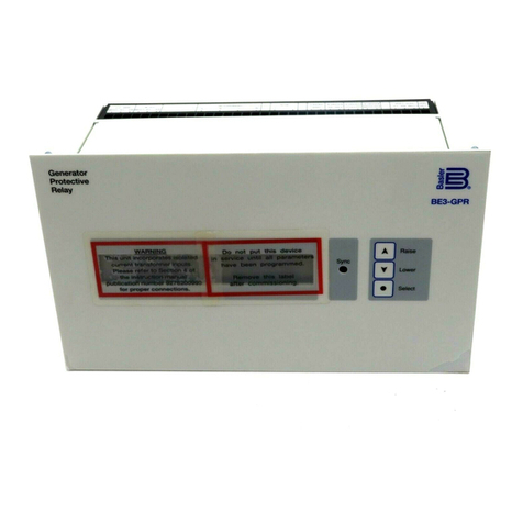
The BE1-25 is a solid-state synchronism check relay designed to permit breaker closure when the
desired maximum phase angle conditions have held for a specified minimum time. The maximum
allowable phase angle and time delay requirements can be set on front panel thumbwheel switches. Five
voltage measuring options are available that identify significant line and bus voltage conditions, and this
information is used to influence the relay output.
Application
BE1-25 Sync-Check Relays are recommended for situations that require verification of synchronism prior
to closing a circuit breaker. Typical applications are:
•Paralleling a generator to a system.
•Reestablishing a connection between two parts of a power system.
•Supervising fast transfer schemes, where fast pickup and dropout of the phase measuring circuit
are required.
If optional voltage measuring circuits are incorporated (Option 2), the BE1-25 can determine whether an
input is live, dead, or in an overvoltage state.
Sync-Check Function
BE1-25 Sync-Check function measures the phase angle between single-phase voltages of line and bus.
Then sync-check verifies that this angle is less than the front panel PHASE ANGLE selector setting. If the
measured angle has met these criteria for the time period defined by the front panel TIME DELAY setting,
the SYNC output contact closes.
Sync-Check Voltage sensing circuits are guaranteed to operate at a
minimum voltage of 80 volts. They are guaranteed not to operate at
voltages less than 20 volts. Some units may operate at voltages in
between these two levels because of the individual characteristics of
specific components. Minimum voltage detection is usually in the
range of 45 to 55 volts.
The allowable phase angle is adjustable over the range of 1 to 99 degrees. The time delay is adjustable
over either of two ranges: 1 to 99 cycles, 50/60 hertz (using the bus frequency as the reference), or 0.1 to
99 seconds (using the internal crystal controlled oscillator as the reference).
An optional target may be specified to indicate operation of the Sync-Check function.
Contact Sensing
To control operation of the relay, an input from the breaker auxiliary 52b contact is required to signal the
breaker status. If the breaker is open, the relay is enabled to perform its function. When the breaker
closes, the 52b input changes state and causes the relay to terminate its close signal.
Two configurations of the 52b contact sensing input are available to provide additional flexibility for the
protection circuit designer:
•Isolated contact sensing monitors a current supplied by the relay through an isolated contact.
•Non-isolated contact sensing monitors the presence of voltage at its input due to the closure of a
contact.
