GE VersaMax GFK-2721A User manual

GE
Intelligent Platforms
Programmable Control Products
VersaMax
PROFINET Scanner Manual, GFK-2721A
December 2013

GFL-002
Warnings, Cautions, and Notes
as Used in this Publication
Warning
Warning notices are used in this publication to emphasize that hazardous voltages,
currents, temperatures, or other conditions that could cause personal injury exist in this
equipment or may be associated with its use.
In situations where inattention could cause either personal injury or damage to equipment,
a Warning notice is used.
Caution
Caution notices are used where equipment might be damaged if care is not taken.
Note: Notes merely call attention to information that is especially significant to
understanding and operating the equipment.
This document is based on information available at the time of its publication. While efforts
have been made to be accurate, the information contained herein does not purport to cover all
details or variations in hardware or software, nor to provide for every possible contingency in
connection with installation, operation, or maintenance. Features may be described herein
which are not present in all hardware and software systems. GE Intelligent Platforms assumes
no obligation of notice to holders of this document with respect to changes subsequently made.
GE Intelligent Platforms makes no representation or warranty, expressed, implied, or statutory
with respect to, and assumes no responsibility for the accuracy, completeness, sufficiency, or
usefulness of the information contained herein. No warranties of merchantability or fitness for
purpose shall apply.
* indicates a trademark of GE Intelligent Platforms, Inc. and/or its affiliates. All other
trademarks are the property of their respective owners.
©Copyright 2011 –2013 GE Intelligent Platforms, Inc.
All Rights Reserved

Contact Information
iii VersaMax PROFINET Scanner Manual–December 2013 GFK-2721A
If you purchased this product through an Authorized Channel Partner, please contact the seller
directly.
General Contact Information
Online technical support and
GlobalCare
http://www.ge-ip.com/support
Additional information
http://www.ge-ip.com/
Solution Provider
solutionprovider.ip@ge.com
Technical Support
If you have technical problems that cannot be resolved with the information in this guide, please
contact us by telephone or email, or on the web at www.ge-ip.com/support
Americas
Online Technical Support
www.ge-ip.com/support
Phone
1-800-433-2682
International Americas Direct Dial
1-780-420-2010 (if toll free 800 option is unavailable)
Technical Support Email
Customer Care Email
custom[email protected]
Primary language of support
English
Europe, the Middle East, and Africa
Online Technical Support
www.ge-ip.com/support
Phone
+800-1-433-2682
EMEA Direct Dial
+420-23-901-5850 (if toll free 800 option is unavailable or
dialing from a mobile telephone)
Technical Support Email
support.emea.ip@ge.com
Customer Care Email
custom[email protected]
Primary languages of support
English, French, German, Italian, Czech, Spanish
Asia Pacific
Online Technical Support
www.ge-ip.com/support
Phone
+86-400-820-8208
+86-21-3217-4826 (India, Indonesia, and Pakistan)
Technical Support Email
Customer Care Email
custom[email protected]


Contents
GFK-2721A v
Introduction................................................................................................................. 1-1
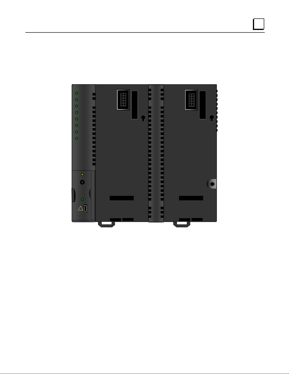
VersaMax PROFINET Scanner Overview........................................................................ 1-2
VersaMax PROFINET Scanner Versions......................................................................... 1-3
VersaMax PROFINET Scanner Specifications................................................................. 1-4
VersaMax PROFINET Scanner Controls and Indicators......................................... 1-5
VersaMax PROFINET Scanner LEDs ..................................................................... 1-5
Power Supply Modules ............................................................................................ 1-8
Ethernet Network Ports............................................................................................ 1-9
USB Port ................................................................................................................ 1-11
Compatible VersaMax Modules, Carriers, and Power Supplies..................................... 1-12
Installation................................................................................................................... 2-1
Module Installation............................................................................................................ 2-2
Cable and Connector Clearance Requirements...................................................... 2-3
General Installation Requirements ................................................................................... 2-4
Installation in Hazardous Areas ............................................................................... 2-4
ATEX Marking.......................................................................................................... 2-4
Installing the Module on a DIN Rail.......................................................................... 2-5
Removing the Module from the DIN Rail ................................................................. 2-5
Installing Power Supplies......................................................................................... 2-7
PROFINET Scanner Power-up and Restart..................................................................... 2-8
LED Operation.................................................................................................................. 2-9
Special LED Blink Patterns.................................................................................... 2-10
Firmware Updates........................................................................................................... 2-11
Firmware Update for Modules in the Remote Node .............................................. 2-11
Configuration.............................................................................................................. 3-1
Configuration Overview .................................................................................................... 3-2
Basic Configuration Steps........................................................................................ 3-2
Configuration Tool.................................................................................................... 3-2
Adding a VersaMax PROFINET Scanner to a LAN.......................................................... 3-3
Configuring VersaMax PROFINET Scanner Parameters........................................ 3-3
Adding VersaMax PROFINET Scanner Power Supplies......................................... 3-5
Adding VersaMax Modules to a Remote Node........................................................ 3-5
Adding Power Supplies between Modules............................................................... 3-5
Configuring VersaMax Module Parameters............................................................. 3-6
Configuring Analog Modules that Have Jumpers..................................................... 3-8
Assigning IO-Device Names........................................................................................... 3-10
After the Configuration is Stored to the IO-Controller..................................................... 3-10
Output Operation ............................................................................................................ 3-11
Clearing the IO-Controller Configuration ........................................................................ 3-11
Replacing PROFINET Scanner Hardware ..................................................................... 3-12

Contents
vi VersaMax PROFINET Scanner Manual–December 2013 GFK-2721A
Diagnostics ................................................................................................................. 4-1
PROFINET Scanner Status and Control Data.................................................................. 4-2
Output Control Bits................................................................................................... 4-2
Input Status Bits....................................................................................................... 4-3
Error Handling................................................................................................................... 4-4
Fatal Error Handling................................................................................................. 4-4
PROFINET Alarms................................................................................................... 4-5
Clearing Faults on VersaMax Analog Modules........................................................ 4-7
PROFINET Module Loss, Add & Mismatch Faults .................................................. 4-8
Diagnostics for BEM003 PROFIBUS DP Networks.......................................................... 4-9
PROFINET Specifications...........................................................................................A-1
PROFINET Protocol Support............................................................................................A-1
Technical Data..................................................................................................................A-2
Limitations.........................................................................................................................A-2
Maintenance Mode...................................................................................................... 5-1
Entering Maintenance Mode and Performing Maintenance ............................................. 5-2
Exiting Maintenance Mode and Restoring Operation....................................................... 5-3
Maintenance Mode Retentiveness through Power Cycle................................................. 5-3

GFK-2721A 1-1
Introduction
This chapter provides an overview of the VersaMax PROFINET Scanner (PNS) module and its
operation. This chapter also includes a list of the VersaMax modules that can be included in the
VersaMax PROFINET Scanner IO-Device.
Chapter 2, Installation, gives instructions for module installation, panel-mounting, grounding,
installing power supplies, and updating firmware. It also describes powerup and restart, and
LED operation.
Chapter 3, Configuration, describes how to configure the PROFINET Scanner and its
associated I/O devices.
Chapter 4, Diagnostics, describes the input and output data that can be used to monitor and
control the PROFINET Scanner. This chapter also explains how the PROFINET Scanner
reports errors to the control system.
Appendix A, PROFINET Specifications, summarizes the features specified for PROFINET
v2.3 Class A IO-Devices that are supported by the VersaMax PROFINET Scanner module.
Chapter
1

1-2 VersaMax PROFINET Scanner Manual –December 2013 GFK-2721A
1
VersaMax PROFINET Scanner Overview
The VersaMax PROFINET Scanner (PNS) module interfaces a remote node of VersaMax
modules to a PROFINET IO network. The PROFINET Scanner scans the modules in its node
(retrieving input data and providing output data), publishes input data on the PROFINET
network at the configured update rate, and receives data for module outputs.
The PNS manages PROFINET communication and module configuration between an IO-
Controller and modules within the remote node. If network communications are lost, the
PROFINET Scanner manages I/O states according to the individual module configurations.
The VersaMax PROFINET Scanner automatically converts between data formats used by
VersaMax modules and the big-endian format used for PROFINET communications.
Input and Output data are coherent over a full scan of the I/O modules. All input data read from
one scan of the modules is kept together and then sent over the PROFINET network. Similarly,
outputs delivered on the network are sent to the I/O modules as a unit. If new outputs arrive
during the writing of data to the output modules, the PNS continues to write to the outputs using
the previous data until all modules have been updated before switching to the newly delivered
data.
VersaMax PROFINET Scanner
IO-Device
Third-Party IO-Device
PROFINET Network
. . .
IO-Controller
VersaMax PROFINET Scanner
IO-Device
VersaMax PROFINET Scanner
IO-Device

GFK-2721A Chapter 1 Introduction 1-3
1
VersaMax PROFINET Scanner Versions
The PNS network interface module is available in two versions to allow you to use the network
media that meets the requirements of your application.
IC200PNS001: Two 10/100 Mbps shielded copper RJ-45 media connectors
IC200PNS002: Two 100Mbps SC–Duplex fiber optic media connectors
PNS001
PWR1 (L)
PWR2 (R)
OK
FAULT
CONNECT
LAN
PORT 1 (L)
PORT 2 (R)
MAINT
COMM
!
The PROFINET Scanner supports the use of either one or two power supplies. Use of the
second power supply is optional. Power supplies mount directly onto the module and latch into
place. The illustration above shows the PROFINET Scanner with no power supplies installed.
Note: For redundancy applications (MRP and Hot Standby CPU redundancy), it is
recommended that each VersaMax PNS be installed and configured with dual
power supplies.

1-4 VersaMax PROFINET Scanner Manual –December 2013 GFK-2721A
1
VersaMax PROFINET Scanner Specifications
PROFINET Support
PROFINET Version 2.3 Class A IO-Device
Redundantly controlled operation conforms to PROFINET V2.3 Type S-2
System Redundancy.
RX3i CPU Version
Required
Firmware version 8.00 or later
RX3i PNC Version
Required
2.00 or later
Proficy Machine Edition
Version Required
Version 8.0 or later
Power Consumption
IC200PNS001: 0.60A at 5VDC
IC200PNS002: 1.10A at 5VDC
Module Dimensions
Height: 132mm (5.2 inches), Width: 134mm (5.28 inches)
Carrier Required
No. Carrier is integrated into the module.
Operating Temperature
Range
0 to 60°C surrounding air temperature without a fan
Number of Port
Connectors
IC200PNS001: Two RJ-45
IC200PNS002: Two SC-Duplex
USB Connector (for
firmware upgrades)
One Micro-B connector. USB 2.0 compliant running at Full-speed
(12 MHz)
PNS Status and Control
Bits
32 input status bits and 32 output control bits
I/O Data Update on the
PROFINET network
Configurable: 1ms, 2ms, 4ms, 8ms, 16ms, 32ms, 64ms, 128ms, 256ms
and 512ms
Number of IP addresses
One. Supports Classless Inter-Domain Routing (CIDR)
Number of MAC
Addresses
Three. One per external port and one internal. External MAC addresses
are only used for specialized Ethernet protocols such as MRP or LLDP
I/O Station Maximum
Limits
Number of I/O Modules per
station
8
I/O data per station
2880 bytes total
1440 bytes of input data
1440 bytes of output data
RoHS Compliance
Yes
Configuration
Configured using Proficy Machine Edition when used with a
PACSystems RX3i PROFINET Controller (PNC) module, as part
of an RX3i PROFINET network.
V2.3 GSDML file is available for import into 3rd-Party tools.
For product standards, general operating specifications, and installation requirements, refer to
the VersaMax I/O Modules Manual, GFK-1504.

GFK-2721A Chapter 1 Introduction 1-5
1
VersaMax PROFINET Scanner Controls and Indicators
The illustration below shows a VersaMax PROFINET Scanner with one power supply installed.
PNS001
PWR1 (L)
PWR2 (R)
OK
FAULT
CONNECT
LAN
PORT 1 (L)
PORT 2 (R)
MAINT
COMM
!
Module LEDs
Maintenance LED and
pushbutton
Micro-USB Port and USB
Communications LED
Protective door covers USB port and
Maintenance Mode pushbutton when closed
VersaMax PROFINET Scanner LEDs
Power Supply LEDs
Each Power Supply LED (PWR1 and PWR2) is ON solid green when a minimum level of power
is being supplied on the corresponding power supply connector on the front panel of the
PROFINET Scanner.
OK LED
The OK LED is solid green ON for normal operation and when the PNS is in Maintenance
Mode. The OK LED flashes or is OFF for all other module states. If there is a failure during
power-up, or a fatal error during normal operation and the scanner is not configured for
automatic restart, the OK LED blinks amber in a failure pattern specific to the error.

1-6 VersaMax PROFINET Scanner Manual –December 2013 GFK-2721A
1
FAULT LED
The FAULT LED indicates the condition of the VersaMax node. On a successful power-up, the
LED is initialized to OFF. The FAULT LED remains OFF during normal operation when no
PROFINET diagnosis conditions are present on the PROFINET Scanner itself, or any module in
the node. When a PROFINET diagnosis condition exists, the FAULT LED turns solid amber.
When all diagnosis conditions have disappeared, the FAULT LED is OFF.
The FAULT LED blinks red (0.5 seconds ON/0.5 seconds OFF) if any of the MAC addresses
read from non-volatile memory on power-up are invalid. The PROFINET Scanner remains
disconnected from the Ethernet network if any of its MAC addresses are invalid.
Missing, failed, or mismatched modules in the remote node do not affect the PROFINET
Scanner FAULT LED.
CONNECT LED
When a new PROFINET Scanner module powers up for the first time, it has no network name.
The CONNECT LED slowly blinks amber to indicate that the module is not ready to use. After a
name is assigned, the CONNECT LED goes OFF.
If the PROFINET Scanner has an assigned network name, the CONNECT LED is OFF after a
successful power up. It turns ON solid Green when the primary IO-Controller has established
communications with the module. It turns ON solid Amber when the Backup IO-Controller has
established communications with the module. It turns OFF when communications are
terminated.
The CONNECT LED blinks amber rapidly when the PROFINET Scanner is updating the
firmware of a module in the remote node, or the PROFINET Scanner is in Maintenance Mode,
indicating that all PROFINET connections are blocked.
LAN LED
The LAN LED blinks ON when the module is actively processing Ethernet packets (Tx/Rx). The
LAN LED is OFF if there is no activity.
Port LEDs (10/100 Mbps and Link/Activity)
The two Port LEDs indicate link speed, link connection and link activity on the Ethernet ports.
Green indicates the associated port is connected at 100Mbps. Amber indicates the associated
port is connected at 10Mbps. If a PORT LED is solid ON, the port is connected but is not
currently receiving or transmitting Ethernet frames. A Port LED blinks when Ethernet frames
are actively being transmitted or received. A Port LED is OFF if its associated Ethernet port is
not connected to an Ethernet switch.

GFK-2721A Chapter 1 Introduction 1-7
1
MAINT LED
The MAINT LED indicates whether or not the VersaMax PNS is in Maintenance Mode. The
MAINT LED blinks amber (0.5 seconds ON/0.5 seconds OFF) when the PNS is in Maintenance
Mode. The LED is OFF when the PNS is working normally. For details on Maintenance Mode
operation, see chapter 5.
COMM LED
The COMM LED is OFF when a USB connection is not established and ON when the link with a
computer is ready. The COMM LED flashes green when there is traffic such as Winloader
activity on the port.
MAINT Switch
The MAINT pushbutton switch can be used to place the VersaMax stick in Maintenance mode.
This switch is located behind the door on the front panel of the PNS to prevent accidental
operation.
To change from Normal Mode to Maintenance Mode, press and hold the MAINT pushbutton for
at least 3 seconds. To exit Maintenance Mode and re-enter Normal Mode, press and hold the
for at least 3 seconds. The new mode will be entered while the pushbutton is depressed. the
MAINT LED indicates when the new mode is active. Any single press of the pushbutton causes
only a single Mode change, regardless of how long the pushbutton is depressed. The PNS does
not change its mode of operation until the pushbutton has been released for at least 0.5
seconds before it is pushed down for another 3 seconds. For details on Maintenance Mode
operation, see chapter 5.

1-8 VersaMax PROFINET Scanner Manual –December 2013 GFK-2721A
1
Power Supply Modules
The PROFINET Scanner can accommodate either one power supply or two redundant power
supplies. If only one power supply is used, it can be installed in either location on the module.
Each power supply location that is used should be included in the configuration. Configured
power supplies will alarm if they are not providing proper voltage. Be sure the installed power
supply matches the configuration.
If two power supplies are installed, they serve as redundant backups for each other. A mix of
AC and DC supplies is supported, but both should be isolated or both non-isolated. Either one
of the power supplies must be capable of supplying all the power required by the node. The two
supplies do not share the load cooperatively.
For PROFINET Scanners included in an RX3i PROFINET Controller configuration, Proficy
Machine Edition automatically calculates whether the power supply or supplies in the
configuration are capable of providing all the power that might be needed by the modules in the
remote node. However, if the remote node is configured by a third-party IO-Controller, this error
checking is not available.
Note: For redundancy applications (MRP and Hot Standby CPU redundancy), it is
recommended that each VersaMax PNS be installed and configured with dual
power supplies.

GFK-2721A Chapter 1 Introduction 1-9
1
Ethernet Network Ports
The two external Ethernet ports are on the bottom of the module. The illustration below is a
bottom view of IC200PNS001 with its two RJ-45 ports.
........
........
Power
Supply
Location
Power
Supply
Location
Hinged
Door
Grounding
Terminal
Port 2
Port 1
RJ-45 Port
SC-Duplex Port
Model IC200PNS001 has two RJ-45 ports, providing 10/100 Mbps copper interfaces. Model
IC200PNS002 has two SC-Duplex ports, providing 100Mbps Multi-Mode fiber interfaces. Each
Ethernet port automatically senses the type of network and adjusts speed and connection
parameters. The PROFINET Scanner requires at least one network be operating at full duplex
for a connection to remain established. The PROFINET protocol may be sent and received over
either or both of the two external ports.
Devices connected to the PROFINET Scanner ports should have Ethernet Autonegotiation
enabled unless the IO-Controller supports configuring the port operation mode. If the
IO-Controller configures the PROFINET Scanner port to a specific setting with autonegotiation
disabled, the device connected to the PROFINET Scanner must be configured for the exact
same setting.
Caution
Both ports on the Ethernet Interface must not be connected, directly or indirectly,
to the same device so as to form a circular network unless Media Redundancy is
enabled with one node actively set up as the Media Redundancy Manager.

1-10 VersaMax PROFINET Scanner Manual –December 2013 GFK-2721A
1
The PROFINET Scanner supports the following network media type and distances.
Media Type
Connector
Type
Wavelength
(nm)
Media
Type
Core
Size(μm)
Modal Bandwidth
(MHz –Km)
Distance (m)
100BASE-FX
SC or
SC-Duplex
1300
MMF
62.5
500
2 –2,000 (Full-
Duplex)
2 –400 (Half-
Duplex)
50
400
50
500
10/100BASE-T
RJ45
-
CAT5/
CAT5e/
CAT6
-
-
100
(maximum)
VersaMax PNS modules and other participating modules can be connected in a
daisy-chain/line, star, or ring (redundant media) topology.
VLAN Priority Settings for the PROFINET Scanner
The VersaMax PNS supports VLAN Priorities as well as incoming traffic that does not include a
VLAN header. The Ethernet switch in the PROFINET Scanner supports two traffic classes,
assigning VLAN Priorities to these classes based on whether rapid arrival of the traffic is critical
to the system, or less important.
VLAN Priority
Preference / Traffic Class
7, 6, 5
Realtime (High Priority). This includes the following Ethernet traffic:
PTCP, MRP, MRRT, RT_CLASS_2, RT_CLASS_1, RT_CLASS_UDP, High Priority
RTA_CLASS_1, High Priority RTA_CLASS_UDP, Low Priority RTA_CLASS_1, Low
Priority RTA_CLASS_UDP
4, 3, 2, 1, 0
Non-realtime (Lower Priority), This includes the following Ethernet traffic: IP, DCP,
other untagged traffic
An external switch that supports only two traffic queues must be configured like the PROFINET
Scanner, as listed in the table above. An external switch that does not support a VLAN priority
mapping that exactly matches the mapping used by the VersaMax PROFINET Scanner can be
used if it can be configured with the following relationships between VLAN priorities:
VLAN Priority 7 is forwarded with at least as much preference as VLAN Priority 6.
VLAN Priority 6 is forwarded with at least as much preference as VLAN Priority 5.
VLAN Priority 5 is forwarded with more preference than VLAN Priorities 0, 1, 2, 3 and 4.
If the external switch does not allow VLAN priority 4 to be treated differently from priority 5, it
should be used only if no device on the network will generate VLAN Priority 4 Ethernet Traffic.

GFK-2721A Chapter 1 Introduction 1-11
1
Media Redundancy Protocol Support
PROFINET Media Redundancy Protocol (MRP) supports devices configured in a ring topology.
It is based on the functions of IEC62439. Media Redundancy Protocol is not routable between
different IP subnets.
Each device within a Redundant Media network has at least two physical pathways to two other
devices on the network. To connect to the ring, each device requires an integrated switch with
at least two external ports (ring ports) that support Media Redundancy Protocol. Devices that
are not MRP-capable can be connected to a device like an MRP-capable switch in the ring, but
they cannot be in the ring themselves. The redundant paths only extend to the devices on the
ring that are MRP-capable and enabled.
One of the devices on the ring must be configured as the Media Redundancy Manager (MRM),
and all the other devices must be configured as Media Redundancy Clients (MRCs). The PNS
can be configured to be an MRC. Configuring the PNS as an MRC alters how the Ethernet ports
connect to the network. They attempt to indicate their state to the MRM before allowing traffic to
flow between the ports and close the ring topology through the internal switch. They also send
out notifications to the MRM when a port is lost. Operation of the PNS is otherwise unchanged.
USB Port
The USB port, located behind the hinged door on the front of the PROFINET Scanner, can be
used to connect a computer for firmware updates for the PROFINET Scanner, and for modules
in the remote node that support indirect firmware updates. The USB port accepts a standard
USB cable (USB Micro B Male to USB Type A Male, not included). The port must be set up
before using it, as described in chapter 2.
Note: The USB port is for firmware upgrades only. It is not intended for permanent connection.

1-12 VersaMax PROFINET Scanner Manual –December 2013 GFK-2721A
1
Compatible VersaMax Modules, Carriers, and Power Supplies
The following modules can be used in a VersaMax PROFINET Scanner IO-Device:
Catalog
Number
Module Description
Supported
Versions
IC200ALG230
Analog Input Module, 12 Bit Voltage/Current 4 Channels
All
IC200ALG240
Analog Input Module, 16 Bit Voltage/Current, 1500VAC Isolation, 8 Channels
1.25 and later
IC200ALG260
Analog Input Module, 12 Bit Voltage/Current 8 Channels
All
IC200ALG261
Analog Input Module, 15 Bit Voltage Differential 8 Channels
All
IC200ALG262
Analog Input Module, 15 Bit Current Differential 8 Channels
All
IC200ALG263
Analog Input Module, 15 Bit Voltage 15 Channels
All
IC200ALG264
Analog Input Module, 15 Bit Current 15 Channels
All
IC200ALG265
Analog Input 15 Bit Voltage 15Ch with enhanced over voltage protection
All
IC200ALG266
Analog Input 15 Bit Current 15Ch with enhanced over voltage protection
All
IC200ALG320
Analog Output Module, 12 Bit Current, 4 Channels
All
IC200ALG321
Analog Output Module, 12 Bit Voltage 4 Channels. 0 to +10VDC Range
All
IC200ALG322
Analog Output Module, 12 Bit Voltage 4 Channels. -10 to +10VDC Range
All
IC200ALG325
Analog Output Module, 13 Bit Voltage 8 Channels
All
IC200ALG326
Analog Output Module, 13 Bit Current 8 Channels
All
IC200ALG327
Analog Output Module, 13 Bit Voltage 12 Channels
All
IC200ALG328
Analog Output Module, 13 Bit Current 12 Channels
All
IC200ALG331
Analog Output Module, 16 Bit Voltage/Current, 1500VAC Isolation, 4 Channels
1.25 and later
IC200ALG430
Analog Mixed Module, Input Current 4 Channels, Output Current 2 Channels
All
IC200ALG431
Analog Mixed Module, 0 to +10VDC Input 4 Channels, Output 0 to +10VDC 2
Channels
All
IC200ALG432
Analog Mixed Module, 12 Bit -10 to +10VDC, Input 4 Channels / Output -10 to
+10VDC 2 Channels
All
IC200ALG620
Analog Input Module, 16 Bit RTD, 4 Channels
1.25 and later
IC200ALG630
Analog Input Module, 16 Bit Thermocouple, 7 Channels
1.25 and later
IC200BEM003
PROFIBUS DP Master
All
IC200CBL105
2 connectors, 0.5m, no shield
All
IC200CBL110
2 connectors, 1.0m, no shield
All
IC200CBL120
2 connectors, 2.0m, no shield
All
IC200CBL230
1 connector, 3.0m, no shield
All
IC200CHS001
Barrier-Style Terminal I/O Carrier
All
IC200CHS002
Box-Style Terminal I/O Carrier
All
IC200CHS003
Connector-Style I/O Carrier
All
IC200CHS005
Spring-Style Terminal I/O Carrier
All
IC200CHS006
Communications Carrier
All
IC200CHS011
Barrier-Style Interposing I/O Terminals
All
IC200CHS012
Box-Style Interposing I/O Terminals
All
IC200CHS014
Thermocouple-Style Interposing I/O Terminals
All

GFK-2721A Chapter 1 Introduction 1-13
1
Catalog
Number
Module Description
Supported
Versions
IC200CHS015
Spring-Style Interposing I/O Terminals
All
IC200CHS022
Compact Box-Style I/O Carrier
All
IC200CHS025
Compact Spring-Style I/O Carrier
All
IC200CHS101
IC200CHS102
Disconnect-Style Interposing I/O Terminals, Main Base
Disconnect-Style Interposing I/O Terminals, Expansion Base
All
IC200CHS111
IC200CHS112
Relay-Style Interposing I/O Terminals, Main Base
Relay-Style Interposing I/O Terminals, Expansion Base
All
IC200CHS121
IC200CHS122
Fuse-Style Interposing I/O Terminals, Main Base
Fuse-Style Interposing I/O Terminals, Expansion Base
All
IC200CMM020
Serial Communications Module (Modbus RTU Master)
All
IC200MDD840
Mixed 24VDC Positive Logic Input Grouped 20 Point / Output Relay 2.0A per
Point Grouped 12 Point Module
All
IC200MDD841
Mixed Module, 24VDC Positive Logic Input 20 Points / Output 12 Point / (4)
High Speed Counter, PWM, or Pulse Train Configurable Points
1.22 and later
IC200MDD842
Mixed 16 Point Grouped Input 24VDC Pos/Neg Logic / 16 Pt Grouped Output
24VDC Pos. Logic 0.5A w/ESCP
All
IC200MDD843
Mixed 24VDC Positive Logic Input Grouped 10 Point / Output Relay 2.0A per
Point 6 Point Module
All
IC200MDD844
Mixed 24 VDC Pos/Neg Logic Input Grouped 16 Point / Output 12/24VDC Pos.
Logic 0.5A 16 Point Module
All
IC200MDD845
Mixed 16 Point Grouped Input 24VDC Pos/Neg Logic / 8 Pt Relay Output 2.0A
per Pt Isolated Form A
All
IC200MDD846
Mixed 120VAC Input 8 Point / Output Relay 2.0A per Point 8 Point Module
All
IC200MDD847
Mixed 240VAC Input 8 Point / Output Relay 2.0A per Point 8 Point Module
All
IC200MDD848
Mixed 120VAC Input 8 Point / Output 120VAC 0.5A per Point Isolated 8 Point
Module
All
IC200MDD849
Mixed 120VAC In Isolated 8 Point / Output Relay 2.0A Isolated 8 Point Module
All
IC200MDD850
Mixed 240VAC In Isolated 4 Point / Output Relay 2.0A Isolated 8 Point Module
All
IC200MDD851
Mixed 5/12VDC Input Group 16Pt / Output 12/24VDC Group 16 Point
All
IC200MDL140
Input 120VAC 8 Point Grouped Module
All
IC200MDL141
Input 240VAC 8 Point Grouped Module
All
IC200MDL143
Input 120VAC 8 Point Isolated Module
All
IC200MDL144
Input 240VAC 4 Point Isolated Module
All
IC200MDL240
Input 120VAC (2 Groups of 8) 16 Point Module
All
IC200MDL241
Input 240VAC (2 Groups of 8) 16 Point Module
All
IC200MDL243
Input 120VAC 16 Point Isolated Module
All
IC200MDL244
Input 240VAC 8 Point Isolated Module
All
IC200MDL329
Output 120VAC 0.5A per Point Isolated 8 Point Module
All
IC200MDL330
Output 120VAC 0.5A per Point Isolated 16 Point Module
All
IC200MDL331
Output 120VAC 2.0A per Point Isolated 8 Point Module
All
IC200MDL631
Input 125VDC Positive/Negative Logic Grouped 8 Point Module
All
IC200MDL632
Input 125VDC Positive/Negative Logic Grouped 16 Point Module
All
IC200MDL635
Input 48VDC Positive/Negative Logic Grouped 16 Point Module
All

1-14 VersaMax PROFINET Scanner Manual –December 2013 GFK-2721A
1
Catalog
Number
Module Description
Supported
Versions
IC200MDL636
Input 48VDC Positive/Negative Logic Grouped 32 Point Module
All
IC200MDL640
Input 24VDC Positive/Negative Logic (2 Groups of 8) 16 Point Module
All
IC200MDL643
Input 5/12VDC (TTL) Positive/Negative Logic 16 Point Module
All
IC200MDL644
Input 5/12VDC (TTL) Positive/Negative Logic Grouped 32 Point Module
All
IC200MDL650
Input 24VDC Positive/Negative Logic (4 Groups of 8) 32 Point Module
All
IC200MDL730
Output 24VDC Positive Logic 2.0A per Point (1 Group of 8) w/ESCP 8 Point
Module
All
IC200MDL740
Output 12/24VDC Positive Logic 0.5A per Point (1 Group of 16) 16 Point
Module
All
IC200MDL741
Output 24VDC Positive Logic 2.0A per Point (1 Group of 16) w/ESCP 16 Point
Module
All
IC200MDL742
Output 24VDC Positive Logic 0.5A per Point (2 Groups of 16) w/ESCP 32
Point Module
All
IC200MDL743
Output 5/12/24VDC Negative Logic 0.5A per Point (1 Group of 16) 16 Point
Module
All
IC200MDL744
Output 5/12/24VDC Negative Logic 0.5A per Point (2 Groups of 16) 32 Point
Module
All
IC200MDL750
Output 12/24VDC Positive Logic 0.5A per Point (2 Groups of 16) 32 Point
Module
All
IC200MDL930
Output Relay 2.0A per Point Isolated Form A 8 Point Module
All
IC200MDL940
Output Relay 2.0A per Point Isolated Form A 16 Point Module
All
IC200PWB001
Power Supply Booster Carrier
All
IC200PWR002
24VDC Expanded 3.3V Power Supply
All
IC200PWR012
24VDC Expanded 3.3V Isolated Power Supply
All
IC200PWR102
120/240VAC Expanded 3.3V Power Supply
All
IC200TBM001
Barrier-Style Auxiliary I/O Terminal Strip
All
IC200TBM002
Box-Style Auxiliary I/O Terminal Strip
All
IC200TBM005
Spring-Style Auxiliary I/O Terminal Strip
All
Table of contents
Other GE Scanner manuals