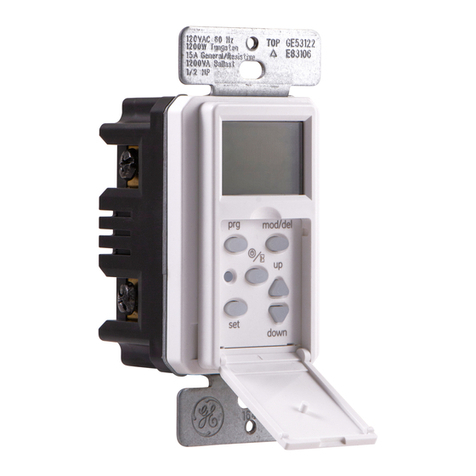
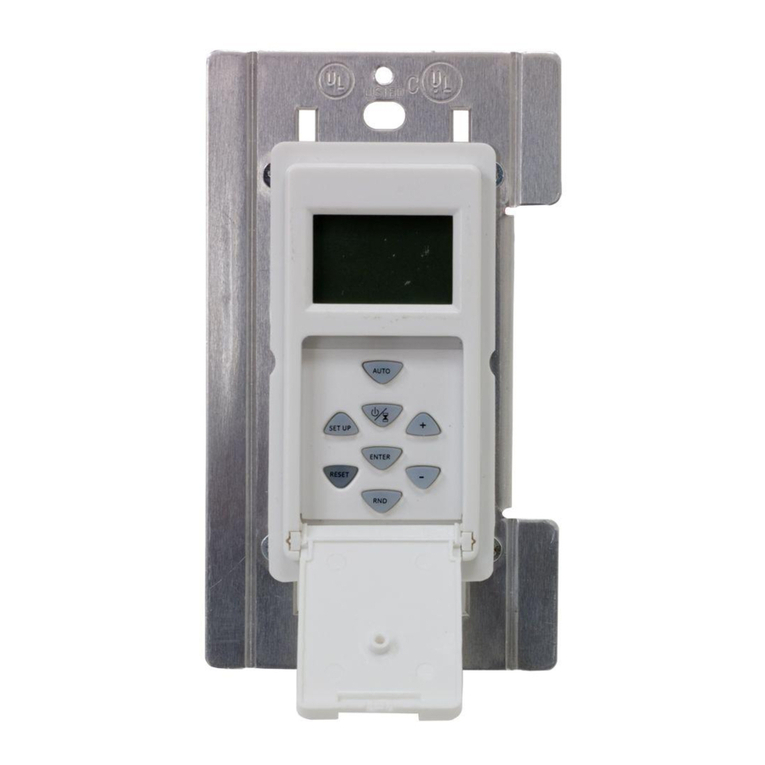
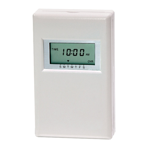
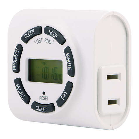
GE SunSmart 15312 User manual

Switch on load side
1. Remove the Load side 3-way switch and remove and label the common wire (4).
2. Connect the jumper wire from the switch to both the load wire and wire (4). You should have three
wires connected with one wire nut.
3. Connect the jumper back to the common input of the 3-way switch.
4. The other wire (5) should stay connected to one of the other connections of the 3-way switch.
5. Carefully tuck the wires into the switch box leaving room for the switch.
6. Using the screws provided install the switch back in the box being careful not to crush or
pinch any wires.
7. Restore power at the circuit breaker or fuse box.
8. Verify that the load turns ON and OFF when you manually turn the timer ON and OFF. Perform this
test with the remote switch in both positions.
9. If the load does not operate properly you need to swap wire (4) and wire (5). This can be done at the
timer or remote switch, after removing power from the circuit at the circuit breaker or fuse box.
10. Verify that the load turns ON and OFF when you manually turn the timer ON and OFF. Perform this
test with the remote switch in both positions. You should hear the timer relay click ON/OFF. If you hear
the relay click but the load does not turn ON/OFF properly, check your wiring.
Existing 3-way installation load side
(The maximum distance between timer and 3-way switch is 100ft)
Switch on line side
1. Remove power from the circuit by turning off the circuit breaker or removing fuse.
2. Remove the 3-way switch from the hot/line side. Remove and label the common wire and remove one
of the other wires.
3. Using the supplied wire nuts, connect the wire removed from the common, the supplied jumper and
the other removed wire (1) together.
4. Connect the jumper back to the common connection of the switch.
5. If the two wires wire (1) and wire (5) on the switch are colored or marked so you can tell them apart
record their markings for use later.
6. Tuck the wires into box leaving room for switch.
7. Install switch into the box.
Timer on Load Side
1. Remove the load side 3-way switch and remove the 3 wires, labeling the common wire.
2. Connect the removed common wire to the timer blue wire.
3. Connect wire (1) to the timer black (line) wire.
4. Connect wire (5) to the timer red (traveler) wire.
5. Connect the white wire (1) of the timer to the white wire in the switch box (neutral). The neutral wires
may be bundled in the back of the switch box with a wire nut. There may be several neutral wires
bound together. Add the neutral to all neutral wires bound together making sure the wire nut is tight.
6. Connect the green wire (3) of the timer to ground in the switch box.
7. Tuck the wires into the switch box leaving room for the timer.
8. Use the supplied screws to install timer being careful not to crush or pinch the wires.
9. Restore power at the circuit breaker or fuse box.
10. If the timer display does not turn on, you may need to swap wire (1) and wire (5). This can be done at
the timer or toggle switch, after removing power from the circuit at the fuse box or circuit breaker.
11. Verify that the load turns ON and OFF when you manually turn the timer ON and OFF. Perform this
test with the remote switch in both positions. You should hear the timer relay click ON/OFF. If you hear
the relay click but the load does not turn ON/OFF properly, check your wiring.
This device complies with part 15 of the FCC rules. Operation is subject to the following two conditions: (1) this device may not
cause harmful interference, and (2) this device must accept any interference received, including interference that may cause
undesired operation.
FCC NOTE: The manufacturer is not responsible for any radio or TV interference caused by unauthorized modifications to this
equipment. Such modifications could void the user’s authority to operate the equipment .
NOTE: This equipment has been tested and found to comply with the limits for a Class B digital device, pursuant to Part 15 of the
FCC Rules. These limits are designed to provide reasonable protection against harmful interference in a residential installation.
This equipment generates, uses and can radiate radio frequency energy and, if not installed and used in accordance with the
instructions may cause harmful interference to radio communications. However, there is no guarantee that interference will not
occur in a particular installation. If this equipment does cause harmful interference to radio or television reception, which can be
determined by turning the equipment off and on, the user is encourage to try to correct the interference by one or more of the
following measures:
• Reorient or relocate the receiving antenna.
• Increase the separation between the equipment and receiver.
• Connect the equipment into an outlet on a circuit different from that to which the receiver is connected.
• Consult the dealer or an experienced radio/TV technician for help.
Step-by-Step
Instructional Video
Changing the color of the timer
This device includes a light almond faceplate. To switch faceplates, proceed as follows:
1. Gently remove the white faceplate using a flat head screwdriver. Starting at the top left corner, gently
pry the faceplate loose. Work around the faceplate until it pops off.
2. Find the light almond faceplate in the package. Place the new faceplate into position and carefully
push until it snaps into position.
Multi-Switch Installations
When combining controls in a wall box, remove all inner side sections
prior to wiring. Use pliers to bend side section up and down until it
breaks off. Repeat for each side section to be removed.
If you are unsure or unclear about this installation or if the wires in
your box do not match the manual (not all switch boxes have neutral
wires), contact a qualified licensed electrician.
Installation instructions (single pole)
1. Turn OFF the main power at the circuit breaker or fuse box.
2. Remove the existing switch.
3. Connect the wires of the timer to the wall box as shown in Figure 1 and Figure 2 using the
wire nuts provided.
a) Connect the hot/live wire of line to the black wire from timer.
b) Connect the hot/live wire of load to the blue wire from timer.
c) Connect the ground wire to the green wire from timer.
d) Connect the neutral wire to the white wire from the timer. Often the neutral (white) wire can be
found in the back of the wire box connected with a wire nut. There may be several neutral wires
bound together. Add the neutral to all neutral wires bound together making sure wire nut is tight.
e) For single pole installation, attach wire nut to red (traveler) wire from the back of the timer. This wire
is not needed in the single pole installation.
Note: Be sure that all wire nuts are secure.
4. Tuck the wires into the wall box leaving room for the timer. Using the screws provided, mount the
timer to the wall box being careful not to crush any wires.
5. Turn main power ON at the circuit breaker.
Typical 3-Way Wiring: In a typical 3-way application there are two 3-way switches. The switch on the
“HOT” side has the common terminal tied to 120VAC. The switch on the “LOAD” side has the common tied
to the lamp/load the switches turn OFF and ON.
Common = Screw terminals found on the back single pole or 3-way
toggle switch.
Existing 3-way installation line side
(The maximum distance between timer and 3-way switch is 100ft.)
Timer on line side
1. Remove power from the circuit by turning off the circuit breaker or removing fuse.
2. Remove the line side 3-way switch and remove wires, label the wire removed from the
common terminal.
3. Connect the line from the common terminal of the original switch wire (1) to the black wire of the
timer using the supplied wire nuts
4. Connect the white wire of the timer to the neutral wire (white). The neutral wires may be bundled
together in the back of the box. There may be several neutral wires bound together. Add the neutral to
all neutral wires bound together making sure wire nut is tight.
5. Connect the two remaining wires left to the red wire (5) and blue wires (4) of the timer. If the wires are
colored or marked you can tell them apart and record their markings for use later.
6. Connect the green wire (3) to the ground wire (green or bare wire in box).
7. Carefully tuck the wires into the switch box leaving room for the timer.
8. Use the screws provided to install the timer in the box being careful not to crush any wires. 15312
Manual Version 2
07-10-2013
www.jascoproducts.com
SunSmart™ Digital Timer Installation
Instructions
Load SideLine Side
Line
Neutral
HH HH
CC
Typical Wiring Schematic for 3-Way Installation
RISK OF ELECTRIC SHOCK
•SHUT OFF POWER AT FUSE BOX OR CIRCUIT
BREAKER BEFORE INSTALLATION
•DO NOT USE IN WET LOCATIONS
•USE INDOORS ONLY
RISK OF FIRE
• DO NOT USE TO CONTROL APPLIANCES THAT
CONTAIN HEATING ELEMENTS (COOKING
APPLIANCES, HEATERS, IRONS, ETC.)
•DO NOT EXCEED ELECTRICAL RATINGS
•USE COPPER WIRE ONLY WITH THIS DEVICE
•DO NOT USE TO CONTROL RECEPTACLES
WARNING
Figure 1
Typical wiring schematic for single pole installation
Black
Black
Load
WhiteWhite
White
Blue
Line
= Wiring nut
Ground
Green Timer
2
1
5
3
2
5
1
3
4
RED
GREEN
BLUE
GROUND
WHITE
BLACK
C
LoadLine
1 = Line
2 = Neutral
3 = Ground
4 = Load
5 = Traveler
C = Common
Typical wiring diagram for 3-way installation
with timer on load side
RED
GREEN
BLUE
WHITE
BLACK
Figure 2
2
4
5
3
2
5
1
3
4
RED
GREEN
BLUE JUMPER
GROUND
WHITE
BLACK
Line Load
C
1 = Line
2 = Neutral
3 = Ground
4 = Load
5 = Traveler
C = Common
Typical wiring diagram for 3-way
installation with timer on hot/line side
MADE IN CHINA
GE is a trademark of General Electric Company and is under
license by Jasco Products Company LLC,10 E. Memorial Rd.,
Oklahoma City, OK 73114.
This Jasco product comes with a 1-year limited warranty.
Visit www.jascoproducts.com for warranty details and
product registration.
Questions? Contact us at 1-800-654-8483 between
7:30AM—5:00PM CST.
15312 Installation Version 4.indd 1 8/1/13 2:05 PM

Cambiar el color del temporizador
Este dispositivo incluye una placa frontal color almendra claro. Para cambiar las placas frontales siga los
siguientes pasos:
1. 1. Retire cuidadosamente la placa frontal blanca con un destornillador de cabeza plana. Comenzando
desde la esquina superior izquierda, afloje ligeramente la placa frontal haciendo palanca hasta retirarla.
2. 2. Busque la placa frontal color almendra claro dentro del paquete. Coloque la nueva placa frontal y
presione cuidadosamente hasta que encaje en su lugar.
Instalación de múltiples interruptores
Cuando combine controles en una caja de embutir, retire todas las
secciones laterales internas antes de realizar la conexión. Utilice
pinzas para mover la sección lateral de arriba hacia abajo hasta
quebrarla. Repita el procedimiento con cada sección lateral que
retire.
Si no está seguro o tiene dudas sobre esta instalación, o si los
cables de su caja no coinciden con los que se indican en el manual
(no todas las cajas de interruptores tienen conductores neutros),
contacte a un electricista profesional capacitado.
Instrucciones de instalación (un solo polo)
1. Desconecte la electricidad principal del disyuntor o caja de fusibles.
2. Retire el interruptor existente.
3. Conecte los cables del temporizador a la caja de embutir como se muestra en las Figuras 1 y 2, utilice
los empalmes de cable provistos.
a) Conecte el cable electrizado/con corriente de la línea al cable negro del temporizador.
b) Conecte el cable electrizado/con corriente de carga al cable azul del temporizador.
c) Conecte el cable de conexión a tierra al cable verde del temporizador.
d) Conecte el cable neutro al cable blanco del temporizador. Muchas veces, el cable neutro (blanco)
se puede encontrar en la parte trasera de la caja de embutir conectado con un empalme de cable.
Puede haber varios cables neutros amarrados. Incluya el neutro a todos los cables neutros amarrados
asegurándose de que el empalme de cable esté ajustado.
e) Para la instalación de un solo polo, fije un empalme de cable al cable rojo (conmutador) de la parte
trasera del temporizador. Este cable no es necesario para la instalación de un solo polo.
Nota: Asegúrese de que todos los empalmes de cable estén ajustados.
4. Introduzca el cable en la caja de embutir, dejando espacio para el temporizador. Use los tornillos
provistos para instalar el temporizador en la caja de embutir, teniendo cuidado de no apretar los cables.
5. Conecte la corriente principal del disyuntor.
Cableado típico de 3 vías: En una aplicación típica de 3 vías hay dos interruptores de 3 vías. El interruptor
del lado con “CORRIENTE” tiene el terminal común conectado a 120 VCA. El interruptor del lado de “CARGA”
tiene el terminal común fijado a la lámpara/carga que los interruptores conectan o desconectan.
Común = Terminales con tornillos ubicados en el interruptor de
palanca de 3 vías o unipolar trasero.
Lado de cable de instalación de 3 vías existente
(la distancia máxima entre el temporizador y el interruptor de 3 vías es de 100 pies)
Lado de cargaLado con corriente
Cable
Neutro
HH HH
CC
Esquema de cableado típico para la instalación de 3 vías
Instrucciones
de instalación
Temporizador en el lado del cable
1. Desconecte el circuito desactivando el disyuntor o retirando el fusible.
2. Retire el interruptor de 3 vías del lado del cable y los cables, y marque el cable que retiró del
terminal común.
3. Conecte el cable común (1) al cable negro del temporizador usando los empalmes de
cable suministrados.
4. Conecte el cable blanco del temporizador al cable neutro (blanco). Los cables neutros pueden estar
amarrados en la parte trasera de la caja. Puede haber varios cables neutros amarrados. Incluya el
neutro a todos los cables neutros amarrados asegurándose de que el empalme de cable esté ajustado.
5. Conecte los dos cables restantes al cable rojo (5) y a los cables azules (4) del temporizador. Si los cables
están coloreados o marcados, puede identificarlos y registrar las marcas para usarlos más adelante.
6. Conecte el cable verde (3) al cable de conexión a tierra (cable verde o cable sin revestir de la caja).
7. Introduzca cuidadosamente los cables en la caja del interruptor dejando espacio para el temporizador.
8. Utilice los tornillos provistos para instalar el temporizador en la caja teniendo cuidado de no
apretar los cables.
Interruptor en el lado de carga
1. Retire el interruptor de 3 vías del lado de carga y marque el cable común (4).
2. Conecte el cable de puente del interruptor al cable de carga y al cable (4). Debe tener tres cables
conectados con un empalme de cable.
3. Conecte nuevamente el puente a la entrada del terminal común del interruptor de 3 vías.
4. El otro cable (5) debe permanecer conectado a una de las otras conexiones del interruptor de 3 vías.
5. Introduzca cuidadosamente los cables en la caja del interruptor dejando espacio para el temporizador.
6. Usando los tornillos provistos, instale el temporizador, teniendo cuidado de no apretar o pellizcar
los cables.
7. Restablezca la electricidad desde el disyuntor o caja de fusibles.
8. Verifique que la carga se conecte y desconecte cuando enciende y apaga manualmente el
temporizador. Realice esta prueba con el interruptor remoto en ambas posiciones.
9. Si la carga no funciona adecuadamente debe intercambiar el cable (4) y el cable (5). Esto puede
realizarse en el temporizador o interruptor remoto, después de desconectar la electricidad del circuito
desde el disyuntor o caja de fusibles.
10. Verifique que la carga se conecte y desconecte cuando enciende y apaga manualmente el
temporizador. Realice esta prueba con el interruptor remoto en ambas posiciones. Debe escuchar un
“clic” cuando el relé del temporizador se enciende y apaga. Si escucha el “clic” del relé pero la carga no
se enciende ni apaga correctamente, revise el cableado.
Lado de carga de instalación de 3 vías existente
(la distancia máxima entre el temporizador y el interruptor de 3 vías es de 100 pies)
Interruptor en el lado de cable
1. Desconecte el circuito desactivando el disyuntor o retirando el fusible.
2. Retire el interruptor de 3 vías del lado de cable con corriente. Retire y marque el cable común y quite uno
de los otros cables.
3. Con los empalmes de cable suministrados conecte el cable que retiró del cable común, el puente
suministrado y el otro cable que haya retirado (1).
4. Conecte nuevamente el puente a la conexión común del interruptor.
5. Si los dos cables (1) y (5) en el interruptor están coloreados o marcados para que pueda distinguirlos,
registre las marcas para usarlos más adelante.
6. Introduzca los cables en la caja dejando espacio para el interruptor.
7. Instale el interruptor en la caja.
Temporizador en el lado de carga
1. Retire el interruptor de 3 vías del lado de carga y los 3 cables y marque el cable común.
2. Conecte el cable común que retiró al cable azul del temporizador.
3. Conecte el cable (1) al cable (línea) negro del temporizador.
4. Conecte el cable (5) al cable (conmutador) rojo del temporizador.
5. Conecte el cable blanco (1) del temporizador al cable blanco en la caja de interruptores (neutro). Los cables
neutros Pueden estar amarrados en la parte trasera de la caja de interruptores con un empalme de
cable. Puede haber varios cables neutros amarrados. Incluya el neutro a todos los cables neutros
amarrados asegurándose de que el empalme del cable esté ajustado.
6. Conecte el cable verde (3) del temporizador a la conexión a tierra en la caja de interruptores.
7. Introduzca los cables en la caja de interruptores dejando espacio para el temporizador.
8. Utilice los tornillos provistos para instalar el temporizador teniendo cuidado de no apretar o
pellizcar los cables.
9. Restablezca la electricidad desde el disyuntor o caja de fusibles.
10. Si la pantalla del temporizador no se enciende, es posible que deba intercambiar el cable (1) y (5). Esto
puede realizarse en el temporizador o interruptor de palanca, después de desconectar la electricidad
del circuito desde el disyuntor o caja de fusibles.
11. Verifique que la carga se conecte y desconecte cuando enciende y apaga manualmente el temporizador.
Realice esta prueba con el interruptor remoto en ambas posiciones. Debe escuchar un “clic” cuando el
relé del temporizador se enciende y apaga. Si escucha el “clic” del relé pero la carga no se enciende ni
apaga correctamente, revise el cableado.
Este dispositivo cumple con la Parte 15 de las Normas de la FCC. La operación está sujeta a las siguientes dos condiciones: (1)
este dispositivo no puede causar interferencias perjudiciales y (2) este dispositivo debe aceptar cualquier interferencia recibida,
incluidas las interferencias que puedan provocar una operación indeseable.
ADVERTENCIA: Los cambios o modificaciones a esta unidad que no hayan sido expresamente aprobados por la parte
responsable del cumplimiento de las reglas, pueden anular la autoridad del usuario para poder operar el equipo.
NOTA: Este equipo ha sido probado y cumple con los límites para un dispositivo digital de Clase B, de conformidad con la Parte
15 de las Normas de la FCC. Estos límites están diseñados para proporcionar una protección razonable contra interferencias en
una instalación residencial. Este equipo genera, utiliza y puede irradiar energía de radiofrecuencia y, si no se instala y utiliza de
acuerdo con las instrucciones, puede causar interferencia dañina a la comunicación por radio.
Sin embargo, no hay ninguna garantía que no ocurra interferencia en una instalación en particular. Si este equipo causa
interferencias perjudiciales a la recepción de radio o televisión, esto se puede comprobar apagando y encendiendo el equipo
repetidamente, se le sugiere al usuario tratar de remediar la interferencia tomando una o más de las siguientes medidas.
• Reorientar o reubicar la antena de recepción
• Aumentar la separación entre el equipo y el receptor
• Conectar el equipo a un tomacorriente en un circuito distinto de aquel al que está conectado el receptor
• Consultar al distribuidor o a un técnico de radio / TV para obtener ayuda.
15312
06-18-2012
www.jascoproducts.com
Esquema de cableado típico para la instalación de un solo polo
Negro
Negro
Carga
BlancoBlanco
Blanco
Azul
Cable
= Empalme
de cable
Conexión
a tierra
Verde
Temporizador
Figura 1
Temporizador Digital SunSmart™
ROJO
VERDE
AZUL
BLANCO
NEGRO
Figura 2
2

4
5
3
2
5
1
3
4
ROJO
VERDE
PUENTE
CONEXIÓN A TIERRA
CableCarga
C
Diagrama de cableado típico para la instalación de
3 vías con temporizador en el lado del cable con corriente
1 = Cable
2 = Neutro
3 = Conexión
a tierra
4 = Carga
5 = Conmutador
C = Común
NEGRO
BLANCO
AZUL
Paso-a-Paso Video
Instructivo
Carga Cable
Diagrama de cableado típico para la instalación de
3 vías con temporizador en la línea del lado de carga
VERDE
AZUL
ROJO
BLANCO
NEGRO CONEXIÓN A TIERRA
2
4
5
3
2
5
1
3
4
JUMPER
C
1 = Cable
2 = Neutro
3 = Conexión
a tierra
4 = Carga
5 = Conmutador
C = Común
HECHO EN CHINA
GE es una marca registrada de la companía General Electric
Company y es utilizada bajo licencia a la companía Jasco
Prodcucts Company LLC, 10 E. Memorial Rd., Oklahoma City,
OK 73114.
Este producto de Jasco Products tiene una garantía limitada
de 1 Año. Visite www.jascoproducts.com para detalles.
¿Tiene preguntas? Comuníquese al 1-800-654-8483 entre las
7:30 a. m. y las 5:00 p. m. CST (hora central estándar).
RIESGO DE CHOQUE ELÉCTRICO
•CORTE LA CORRIENTE ANTES DE EFECTUAR
UNA INSTALACIÓN
•NO LO USE EN LUGARES HÚMEDOS
•USE SOLAMENTE EN INTERIORES
RIESGO DE INCENDIO
• NO USE PARA CONTROLAR ELECTRODOMÉSTICOS
QUE CONTENGAN ELEMENTOS CALORÍFICOS
(APARATOS PARA COCINAR, CALENTADORES,
PLANCHAS, ETC.).
•NO EXCEDA LOS LÍMITES ELÉCTRICOS PERMITIDOS
•UTILÍCELO CON ALAMBRE DE COBRE ÚNICAMENTE
•NO LO UTILICE PARA CONTROLAR RECEPTÁCULOS
ADVERTENCIA
15312 Installation Version 4.indd 2 8/1/13 2:05 PM
Table of contents
Languages:
Other GE Timer manuals