manuals.online logo
Brands
  1. Home
  2. •
  3. Brands
  4. •
  5. GE
  6. •
  7. Ventilation Hood
  8. •
  9. GE Monogram ZV950 User manual

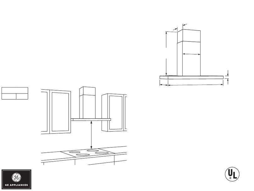
GE Monogram ZV950 User manual

Installation
Instructions
ZV950
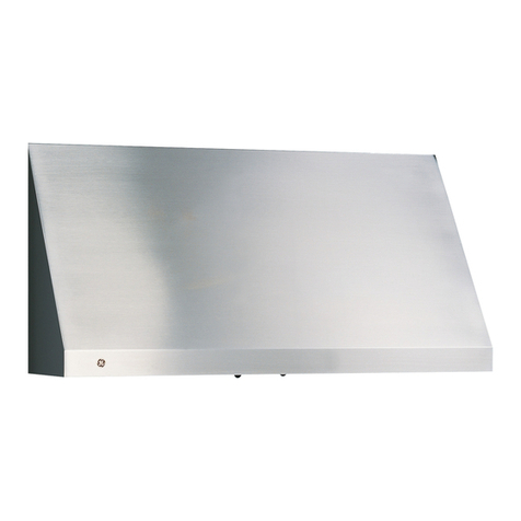
36"Stainless Steel
Vent Hood
Safer information
BEFORE YOU BEGIN
Read these instructions completely and carefully.
•IMPORTANT- S.vethesei.st uctio.s
for local inspector's use.
•IMPORTANT- Obsexve.llgovex.i.g
codes and ordinances.
* Note to Installer - Be sure to leave these
instructions with the Consmner.
* Note to Consumer - Keep these instructions
with your Owner's Manual for fixture refe-rence.
* Skill Level - Installation of this appliance requires
basic mechanical and electrical skills.
* Completion time - 1 to 3 hours.
* Proper installation is the responsibility of the
installer. Product fhihue due to improper installation
is not covered under the Warranty.
For Monogram local service in your area,
1.800.444.1845.
For Monogram service in Canada, call
1.800.561.3344.
For Monogram Parts and Accessories, call
1.800.626.2002.
CAUTION:
Due to the weight and size of these vent hoods,
and to reduce the risk of personal ix_jury or damage
to the product, TWO PEOPLE ARE REQUIRED
FOR PROPER INSTALLATION.
PRUDENCE
cause du poids et de la mille de ces buttes,
et pore r_duire le risque de blessures et de
dommages, IL FAUT DEUX PERSONNES POUR
FAIRE L'INSTALLATION CORRECTEMENT.
WARNING:
To reduce the risk of fire or electrical shock, do not
use this range hood with any external solid-state speed
control device. Any such alteration flom original
factory wiring could result in damage to the unit
and/or create an electrical safety hazard.
AVERTISSENIENT
Pore r&hfire le risque d'incendie ou de choc
_lectrique, iXne taut pan utiliser cette butte avec
un r_gulatem de vitesse _lectronique externe. Toute
modification de ce type du branchement d'usine peut
endommager l'appareil ou crier un risque de choc
_lectrique.
TO REDUCE THE RISK OF FIRE, USE ONLY
METAL DUCTWORK.
2
WARNING" [] TO REDUCE THE RISK
OF FIRE, ELECTRICAL SHOCK OR INJURY TO
PERSONS, OBSERVE THE FOLLOWING:
A. Use this unit only in the manner intended by the
manuf_mmrer. If you have any questions, contact
the manufacturer.
B. Before servicing or cleaning unit, switch
power off at the service panel and lock service
panel to prevent power flom being switched on
accidenmll> If the service panel cannot be locked,
fasten a mg or prominent warning label to the
panel.
AVERTISSENIENT
POUR RI_DUIRE LE RISQUE D'INCENDIE, DE
CHOC I_LECTRIQUE OU DE BLESSURES, IL FAUT
OBSERVER LES REGI,ES SUIVANTES :
A. Utiliser cet appareil uniquement de la mani_re
pr&_ue par le fabricant. En can de question,
consulter le fabricant.
B. Avant tot]re intervention ou nettoyage, couper
l'alimenmtion _lectrique au disjoncteur et
verrouiller le panneau du disjoncteur pour _viter
la raise sous tension accidentelle. S'il n'est pas
possible de verrouiller le panneau du disjonctem;
attacher un placard ou une &iquette tr&s visible
au panneau.
* For general ventilating use onlyo Do not use to
exhaust hazardous or explosive materials or vapors.
* Structural flaming, installation work and electrical
wiring must be done by qualified person (s)
in accordance with all applicable codes and
standards including fire-rated construction.
* Sufficient air is needed for proper combustion
and exhausting of gases through the flue (chimney)
of tirol bmning equipment to prevent back
drafting. Follow the beating equipment
manufacturer's guidelines and safety standards such
as those published by the National Fire Protection
Association (NFPA), and the American Society for
Heating, Refligeration and Air Conditioning
Engineers (ASHRAE), and the local code
authorities.
* Local codes vary. Installation electrical connections
and grounding must comply with applicable codes.
In the absence of local codes, the vent should be
installed in accordance with National Electrical
Code ANSI/NFPA 70-11990or latest edition.
CAUTION"[] To reduce risk of fire and to
properly exhaust air, be sure to duct air outside-Do
not vent exhaust air into spaces within walls or
ceilings or into attics, crawl spaces or garages.
PRODENCE-I t ,utpx-e. b-esol.
d'insmller un conduit vers Fext&ieur pore r&tuire
]e risque d'incendie et pouvoir &'acuer l'air
correctement. IXne f_mt pan &_acuer Fair darts
l'espace entre les patois d'un tour, un plafond
ou un grenim; un espace sanitaire ou un garage.
Desi n information
CONTENTS
Design Information
Product Dimensions and Clearances ........................... 3-4
Optional Accessories ......................................................... 4 Step
Installation Preparation Step
Advance Planning, Step
Ductwork, Framing ......................................................... 5 Step
Power Supp b, ..................................................................... 5 Step
Duct Fittings ...................................................................... 6 Step
Tools and Materials Required .......................................... 7 Step
Remove the Packaging ...................................................... 7 Step
Check Installation Hardware ........................................... 8 Step
Ductwork, Wiring i,ocations ............................................. 8
Installation Instructions
1, Install Framing fin Hood Support ...................... 9
2, Install Mounting Brackets .................................... 9
3, Install Duct Bracket ............................................
4, Install the Hood ..................................................
5, Connect Ductwork ..............................................
6, Connect Electrical ..............................................
7, Install Duct Covers ..............................................
8, Install Filters ........................................................
9, Finalize Installation ............................................
0
0
1
1
1
2
2
PRODUCT DIMENSIONS AND CLEARANCES
36" Vent Hood installation Combinations
This Stainless Steel Hood can be installed over any
Monogram cooktop, including the Professional 36"
cooktop and 30" or 36" range.
_Height
to Ceiling
i...... ......
*The supplied duct cover fits 8if, to lOft. ceilings.
The vent hood must be installed 24" rain. and 30" max.
above the cooldng surf_ce. The hood installation height,
fiom the cooking suif_tce to the bottom of the hood,
depends upon ceiling height.
ofI
Installation
HeightDepending
on CeilingHeight
r
o
36" Min.
o
o
o
Cooking surface to bottom of hood should be:
* 25-1/2" max. for 8 R. ceiling height.
* 25-1/2" to 30" for 9 fL ceiling height.
* 30" rain. for 10 fL ceiling height.
Plan the installation height careflflly to avoid unsightly
gaps above the hood.
Installation with 36" Professional Cooktop or Range
(Models ZGU36 or ZDP36)
This hood must be installed, 0 rain. above a Monogram
Professional Cooktop or Range. Ceiling height for this
installation combination tllust be at least 8'5" high.
Note: The supplied 2-piece duct cover is adjusmble to fit
8 fL to 10 fL ceilings. For ceiling heights greater than
10 fL and up to 14 fL, order ZX14SDSS stainless steel
duct cover accessory.
ZV950SDSS Duct Cover ZX14SDSS Duct Cover
Dimensions Dimensions
fL-i 11_
1FI
11"q
3
Desi n information
PRODUCT DiMENSiONS AND
CLEARANCES (cont.)
Using Duct Cover Accessories
A Duct Cover Accessory may be reqtfired for yore
hood installation height. Use this chart to determine
installation height and accessory for your ceiling height.
Actual
Ceiling * Possible Hood
Height installation Height
7' 11" 24-I/2"
8' 0" 25-1/2"
8' 1" 25-1/2" to 26-1/2"
8' 2" 25-1/2" to 27-1/2"
8' 3" 25-1/2" to 28-1/2"
8' 4" 25-1/2" to 29-1/2"
8' 5" 25-1/2" to 30"
8' 6" 25-1/2" to 30"
8' 7" 25-1/2" to 30"
8' 8" 25-1/2" to 30"
8' 9" 25-1/2" to 30"
8' 10" 25-1/2" to 30"
8' 11" 25-1/2" to 30"
9' 0" 25-1/2" to 30"
9' 1" 26-1/2" to 30"
9' 2" 26-1/2" to 30"
9' 3" 26-1/2" to 30"
ZV950SDSSInstallationHeights
Duct Dover
9' 4" 26-1/2" to 30"
9' 5" 26-1/2" to 30"
9' 6" 30" rain,
9' 7" 30" rain,
9' 8" 30" rain,
9' 9" 30" rain,
9' 10" 30" rain,
9' 11" 30" rain,
10'0"
30" rain.
14'0"
_o
* Based on 36" countertop height,
The serial plate is located behind the removable filters,
OPTIONAL ACCESSORIES
ZX14SDSS, optional stainless steel duct cover
is available for ceiling heights greater than 10 fL
and up to 14 fL
Order the optional duct cover at the same time
as the vent hood and have on site beff_re installation.
Note: Duct covers Illust be installed as shown in this
book. Do not "build-in" the duct cover. If service
is required, the duct cover must be removed to access
hood components°
4
installation Preparation
ADVANCE PLANNING
Ductwork Planning
* Determine the exact location of the vent hood.
* Plan the route for venting exhaust to the outdoors.
e Use the shortest and straightest duct route possible.
For satisfacto Wperformance, duct run should
not exceed lO0 equivalent length for any duct
configurations.
* Refer to "Duct Fittings" chart to compute
the maximum permissible length for duct runs
to the outdoors.
CAUTION: To,-ed.ce,-,s.of.,e..dto
properly exhaust air, be sure to duct air outside-Do not
vent exhaust air into spaces within walls or ceilings
or into attics, crawl spaces or garages.
PRUDENCE -i1 p,-e.d,-eso,.
d'installer un conduit vers l'ext_rieur pour r_duire le
risque d'incendie et pouvoir &_acuer l'air correctement.
I1 ne f_tut pas _vacuer l'air darts l'espace entre les patois
d ,un ram; un plaKmd ou un grenie_; un espace sanitaire
ou un garage.
• Use metal duct_,vork. These hoods must use 8" round
duct. It can transition to 3-1/4" x 12", reducing the
maximum equivalent duct length to 75 feet.
• Install a wall cap with damper or roof cap at the
exterior opening° Order the wall or roof cap
and any transition needed in advance.
Wall Framing for Adequate Support
* This vent hood is heax T. Adequate structural support
must be provided. The hood must be secured to
vertical studs in the wall, or to a horizontal support.
See page 9.
* We strongly recommend that the vent hood with duct
cover be on site before final fiaming and wall
finishing. This will also help to accurately locate
the ductwork and electrical service.
POWER SUPPLY
IMPORTANT - (Please read careflflly)
WARNING:
FOR PERSONAl, SAFETY, THIS APPIffANCE MUST BE
PROPERIX (;ROUNDED.
AVERTISSEMENT
POUR DES RAISONS DE SI_CURITI_, CET APPAREIL
DOIT I_TRE CORRECTEMENT MIS A LA TERRE.
Remove house fl_se or open circuit breaker before
beginning installation.
Do not use an extension cord or adapter plug with this
appliance. Follow National Electrical Code or prevailing
local codes and ordinances.
* Route house wiring as close to the installation location
as possible in the ceiling or soflqt. Wiring should enter
at least 4" above the bracket on the right side.
* Connect the wiring to the house wiring in accordance
with local codes.
Grounding instructions
The grounding conductor must be connected
to a ground metal, permanent wiring system, or an
equipment-grounding terminal or lead on the hood.
WARNING: Tl.e,..p,-ope,-co..ect,o.of
the equipment-grounding conductor can result in a risk
of electric shock. Check with a qualified electrician or
service representative if you are in doubt whether the
appliance is properly grounded.
AVERTISSEMENT
Electrical supply
This vent hood must be supplied with 120V, 60Hz, and
connected to an individual, properly grounded branch
circuit, and protected by a 15 or 20 amp circuit breaker
or time delay fl_se.
* Wiring must be 2 wire with ground.
* If the electrical supply does not meet the above
requirements, call a licensed electrician before
proceeding°
Le mauvais branchement du fil de raise _'tla terre pent
causer un choc _lectrique. En cas de doute, consulter un
_lectricien qualifi_ ou un technicien pour d_terminer si
l'appareil est _'_la terre.
5
installation Preparation
DUCT FiTTiNGS
Use this chart to compute maxhnmn
permissible lengths for duct runs to
O tltdooYs.
Note: Do not exceed maximum
equivalent lengths!
Maximum duct length:
100 ft. for range hoods.
?ermissible
Flexible ducting:
If flexible metal ducfing is used, all
the equivalent feet values in the ruble
should be doubled. The flexible metal
duct should be straight and smooth
and extended as much as possible.
Do NOT use flexible plastic ducting.
Note: Anyhomeventilation system,suchas aventilation
hood,mayinterrupttheproperflow ofcombustionair and
exhaustrequiredbyfireplaces,gasfurnaces,gaswater
heatersandothernaturallyventedsystems.Tominimize
the chanceof interruptionof suchnaturallyvented
systems,follow theheatingequipmentmanufacturer's
guidelinesandsafetystandardssuchasthosepublished
by NFPAandASHRAE
Duct Piece Dimensions
Round,
straight
3-1/4" x 12"
straight
(_ 90° elbow
(_ 45° elbo_a
3-1/4" x 12"
90° elbo_
%
©
Equivalent
Length*
IIL
(per foot
length)
lft.
(per foot
length)
17 ft.
10ft.
43 ft.
Quantib_
Used
3-1/4" x 12"
45° elbox_ 26 ft.
3-1/4" x 12"
90 ° flat elb{m 102 ft.
_" I'Ot/lld to
3-1/4" x 12" transition 2 ft.
3-1/4" x 12"
to 8" round transition 5 ft.
_" I'OHlld
to 3-1/4" x 12"
transition 90° elbow 6 ft
3-1/4" x 12" to 8" 3I'Ot/lld transition 90 ° elb(m 1: ft.
Round
wall cap
with damper 32 ft.
3-1/4" x 12" x_all cap
x_ith damper 75 ft.
Total
Equivalent
Length
Round
roof cap 44 ft.
"Actual lengthof straight duct plusduct fitting equivalent.
Equivalentlength ofduct piecesarebasedon actual
testsconductedbyGEEvaluationEngineeringandreflect
requirementsfor good venting performancewith any
ventilation hood.
Total Duct Run
6
installation Preparation
TOOLS AND MATERIALS REQUIRED
{NOT SUPPLIEDI
. Tapemeasure
Knife
Spirit level
Wire cutter/stripper
Wire nuts
Electric drill with 1/8"and 3/8" bits
Phillipsand flat blade screwdrivers
. Hammer
. Pliers
. Safety glasses
. Duct tape
.Tape to mount template
. Gloves to protect against sharp edges
.120V 60Hz. 15 or 20 Amp, 2 wire with ground.
Properly grounded branch circuit.
. Strain relief for junction cover.
.8" round metal duct, length to suit installation.
REMOVE THE PACKAGING
The vent hood is shipped secured to a shipping board
with a shipping bracket and 4 screws.
* Remove the duct cove_, parts box and other packaging.
* i,if_ the hood out of the box.
* Remove and properly discard the plastic wrapping.
TopOtHood
// '_ /
/
/
Junction TopShippingScrews
Box ScrewsandShippingBracket
* Locate and remove 2 screws at the top of the hood.
Remove 2 screws at the bottom behind the filter
guides on the left and right sides. Remove the
shipping bracket fiom behind the blower housing.
Discard the shipping bracket and board.
* Removej unction box cover
* Install strain relief into junction box cover.
installation Preparation
CHECK iNSTALLATiON HARDWARE
i,ocate the hardware accessory box packed with the
hood and check contents.
8Wood 4Wall
Screws Fasteners
2Large
FlatWashers
2 Mounting Brackets
ggg
3Phillips Head
Decorative Screws
3Stainless Steel GreaseFilters
L---16"'?
DuctCover Bracket
2-piece
Decorative Duct Cover
(dimension shown
for reference only)
i
i
,I_, i
Wall Mount Template
8
DUCTWORK, WIRING LOCATIONS
Determine the exact locadon of the vent hood.
* i,ocate the template packed with the literature.
-Measure 36" from the floor to the top of the cooking
smfhce. Add 25-1/2" (or other recommended space)
f)om the cooking surface to the bottonl of the hood.
Mark that location.
- Use a level to draw a straight pencil line on the wall.
,, /FOR CEILING
6-1/4 ...... _/VENT DUCTING
benterllne /o wall /_,_;
8-1/2" Dia.Hole( i
i
\\\\\\ i' Centerline
_,', 8" Min Above
)_Top Mounting
FORWALLVENTDUCT/[ BracketHoles
i
£
i
W-I
-Tape the template in position along the penciled
line. CHECK TO BE SURE THE TEMPI,ATE IS
I,EVEI.
Ceiling ducfing:
If duct_,w)rk will vent straight up to the ceiling:
* Use a level to draw a line straight up, f]om the
centerline on the template to the ceiling.
* Measure 6-1/4" flom the back wall to the centerline
of a 8-1/2" hole on the ceiling.
Note: If drywall is not present, add drywall thickness
to the 6-1/4"dimension.
Wall Ducfing:
If ductwork will vent to the rear:
* Use the level to draw a line straight up f_om the
centerline on the template.
* Measure at least S" above the top mot]nfing bracket
boles shown on the template to the centerline of an
8-1/2" dia. duct bole. (Hole may be elongated for
duct elbow.)
HOUSE WIRING LOCATION:
* The junction box is located on the top of the hood,
at the back right side.
* Route house wiring as close to the ceiling location
as possible, through the ceiling, soffit or back wall.
Wiring should enter at least 4" above the bracket
on the right side.
installation instructions
iNSTALL FRAMING
FOR HOOD SUPPORT
iIMPORTANT: Framing must be capableof supporting 100 Ibs.
8"Min. Openingfor Ductwork
I:
Centerline of
Installation
Space
View From Rear
)
]"x6" Min
Mounting
Support
JJ
If drywall is present, mark the screw hole locations for
the top mounting brackets. Remove the template°
• Cutaway enough dITwall to expose 2 vertical studs at
the bracket location indicated on the template°
• Install a horizontal support at least 1" x 6" between t_,vo
wall studs at the top bracket installation location° The
horizontal support must be flush with the room side of
the studs. Use cleats behind both sides of the support
to sect]re the support to wall studs.
• Reinstall drywall.
iNSTALL MOUNTING BRACKETS
This vent hood must he secured to the horizontal support or wall
studs.
• With the template taped in place, use a punch
to mark all mounting screw locafionso
• Drill 1/8" pilot holes at the 6 punched locafionso
• Remove the template°
• The 4 support bracket holes must enter studs
or the horizontal support°
Note: Screws "A" and
"B" are pre-assembled
onto the brackets. Do not
remove these screws.
e
• The t_,volower holes can be enlarged if they did not
enter studs to 3/8"o Tap anchors K_r wall fasteners
into the bottom holes.
- Screws should be inserted by hand into the fasteners
to allow anchors to expand against the wall material.
Remove the screws for final installation.
• Secure the mounting brackets to the wall studs with
wood screws provided.
9
Installation instructions
iNSTALL DUCT BRACKET
The duct bracket must be installed against the ceiling.
This bracket will hold the decorative duct cover in place
at the top.
* Install the 2 small screws into the sides of the duct
bracket. Remove the screws. Pre-tapping the holes will
insme ease of final installation.
Pre-Tap I I I I Pie-Tap
Side ' 'Side
Screw Screw
Secure the bracket to the ceiling and wall:
* Mark tile 4 screw hole locations.
* Drill 1/8" pilot holes in marked bracket location.
* If pilot holes do not enter studs, enlarge tlle holes to
3/8" and install wall fastener anchors.
* Drive screws, by hand, into the fasteners to allow
anchors to expand. Remove tlle screws.
* Secure tlle bracket to the ceiling and wall with wood
screws and/or fasteners.
iNSTALL THE HOOD
Place the hood on the brackets and slide lef_ to right
to align with rectangular slots at the top.
*A(0ust the installation height by tightening or
loosening the screws '%" at the bottom of the brackets.
*Align the hood lower mounting holes with pilot holes
in the wall.
* Using two large fiat washers (supplied), install wood
screws or wall fastener screws, loosel 5 into lower
mounting holes. Do not tighten.
LowerMountingHoles
BracketTabs
/Screws_,
/"B" _
/',,
/
* Level the hood by tightening or loosening the screws
"A" located on the bottom mounting brackets.
* Tighten lower mounting screws.
* Tighten screws "g" located at the top of the mounting
bracket against the hood to clamp the position.
Do not overfighten screws.
10
Installation instructions
CONNECT DUCTWORK
.Install ductwork, making connections in direction
of airflow as illustrated.
* Push duct over the exhaust outlet until it reaches
the duct stops.
* Secmejoints in ductwork with sheetmetal screws.
* Wrap all duct joints with duct rope for an airtight seal.
* Use duct tape to seal the flange connection.
CAUTION"[]Do not use sheet metal screws at
the hood flange connection. Doing so will prevent proper
damper operations. Seal connection with rope only.
PRUDENCE
I1ne faut pas utiliser de vis autoraurdeuses _'_la connexion
du collet de la hotte. Ceci emp6cherait le bon
fonctionnement du registre. N'udliser que du ruban
adh6sif pour assurer l'&anch_it6 du raccord.
DuctTape
Over Seam
ii
L
W
Duct Stops __
CON NECT ELECTRICAL Verify that power is turned off at the source.
WARNING" [] If house wiring is not 2-wire
with a ground wire, a ground must be provided by the
installer When house wiring is ahuninmn, be sure to use
U.L. approved anti-oxidant compound and aluminmn-to-
copper connec[ois.
AVERTISSENIENT
Si la maison n'est pas ci'd)16eavec deux ills et un fil de
terre, l'insmllateur dolt installer un fil de tene. Quand
les ills sont en aluminimn, i1faut prendre soin d'utiliser
des connecteurs aluminimn kcuiwe avec une p;'_teanti-
oxydante approuv6e par UL.
* Insert house wiring through strain relief and tighten.
* Connect white leads to branch chcuit white lead.
* Connect black leads to branch chcuit black lead.
* Connect green/yellow leads to branch chcuit green
lead or bare ground lead.
* Secure all connections with wire nuts on each electrical
connector.
* Push wires into junction box and replace cover. Be sme
wires are not pinched.
iNSTALL DUCT COVERS
Mounting Screws
* Place the decorative duct
covers on top of the hood.
* Insert the lower portion
of the duct cover into the
impressions on the top of
the hood. Bottom
Notches * Extend the inner duct upwards to the ceiling bracket.
* Secure the duct cover to the bracket with the 2 small
Phillips screws provided.
* Install the decorative screw in the lower lef* hole on the
duct cover as shown.
11

Other manuals for Monogram ZV950

6

Other GE Ventilation Hood manuals

GE Monogram ZV850 User manual

GE

GE Monogram ZV850 User manual

GE JV395 Training manual

GE

GE JV395 Training manual

GE Appliances CV936 Operating instructions

GE

GE Appliances CV936 Operating instructions

GE Monogram ZV30 User manual

GE

GE Monogram ZV30 User manual

GE Monogram ZV830 User manual

GE

GE Monogram ZV830 User manual

GE JVB67 Original instructions

GE

GE JVB67 Original instructions

GE Cafe CV966TSS Manual

GE

GE Cafe CV966TSS Manual

GE JV247 Operating instructions

GE

GE JV247 Operating instructions

GE JV666HSS Original instructions

GE

GE JV666HSS Original instructions

GE JVC3300J Series Manual

GE

GE JVC3300J Series Manual

GE Monogram ZVB36BH User guide

GE

GE Monogram ZVB36BH User guide

GE JV535 Operating instructions

GE

GE JV535 Operating instructions

GE PVB98DTBB Manual

GE

GE PVB98DTBB Manual

GE ZV48T User manual

GE

GE ZV48T User manual

GE MNU720 User manual

GE

GE MNU720 User manual

GE UVC9480 Original instructions

GE

GE UVC9480 Original instructions

GE Profile JV536HSS User guide

GE

GE Profile JV536HSS User guide

GE Monogram ZV850 User manual

GE

GE Monogram ZV850 User manual

GE Appliances CV966 Original instructions

GE

GE Appliances CV966 Original instructions

GE PVW7361 User manual

GE

GE PVW7361 User manual

GE UVI7361 Original instructions

GE

GE UVI7361 Original instructions

GE Monogram ZV755 User manual

GE

GE Monogram ZV755 User manual

GE GE Deluxe JV347X User manual

GE

GE GE Deluxe JV347X User manual

GE PVUS830 Operating instructions

GE

GE PVUS830 Operating instructions

Popular Ventilation Hood manuals by other brands

B.S. Service CP EV User instructions

B.S. Service

B.S. Service CP EV User instructions

Progress PDV9175B user manual

Progress

Progress PDV9175B user manual

Zephyr Venezia Use, care and installation guide

Zephyr

Zephyr Venezia Use, care and installation guide

Galvamet Exclusive THEOREMA Maintenance instructions

Galvamet

Galvamet Exclusive THEOREMA Maintenance instructions

AEG 222 D Installation and operating instructions

AEG

AEG 222 D Installation and operating instructions

Electrolux Icon E36WC45FSS Factory parts catalog

Electrolux

Electrolux Icon E36WC45FSS Factory parts catalog

Zanussi ZHC 605 Installation, use and maintenance instructions

Zanussi

Zanussi ZHC 605 Installation, use and maintenance instructions

THERMEx Passat II Mounting instruction

THERMEx

THERMEx Passat II Mounting instruction

NuTone NS130BL instruction manual

NuTone

NuTone NS130BL instruction manual

AEG DEI 60 PL 2 Instructions for installation and use

AEG

AEG DEI 60 PL 2 Instructions for installation and use

Broan E60000 SERIES installation instructions

Broan

Broan E60000 SERIES installation instructions

Roros Metall Sigma User instructions

Roros Metall

Roros Metall Sigma User instructions

AEG 350 D operating instructions

AEG

AEG 350 D operating instructions

Bull 1250 CFM Installation instructions & use & care guide

Bull

Bull 1250 CFM Installation instructions & use & care guide

Franke FJO 634 XS user manual

Franke

Franke FJO 634 XS user manual

Hansa OMP6553BGH operating instructions

Hansa

Hansa OMP6553BGH operating instructions

La Germania KV90LAG1NB installation manual

La Germania

La Germania KV90LAG1NB installation manual

FALMEC Sintesi Instruction booklet

FALMEC

FALMEC Sintesi Instruction booklet

manuals.online logo
manuals.online logoBrands
  • About & Mission
  • Contact us
  • Privacy Policy
  • Terms and Conditions

Copyright 2025 Manuals.Online. All Rights Reserved.