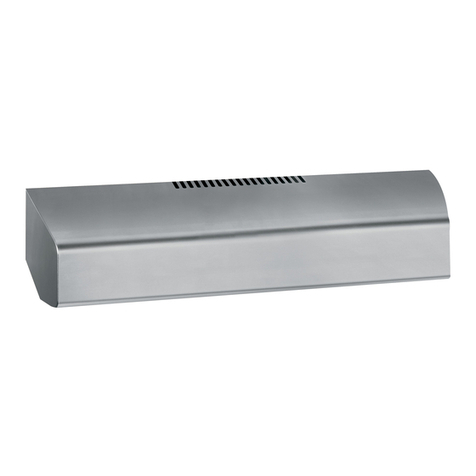
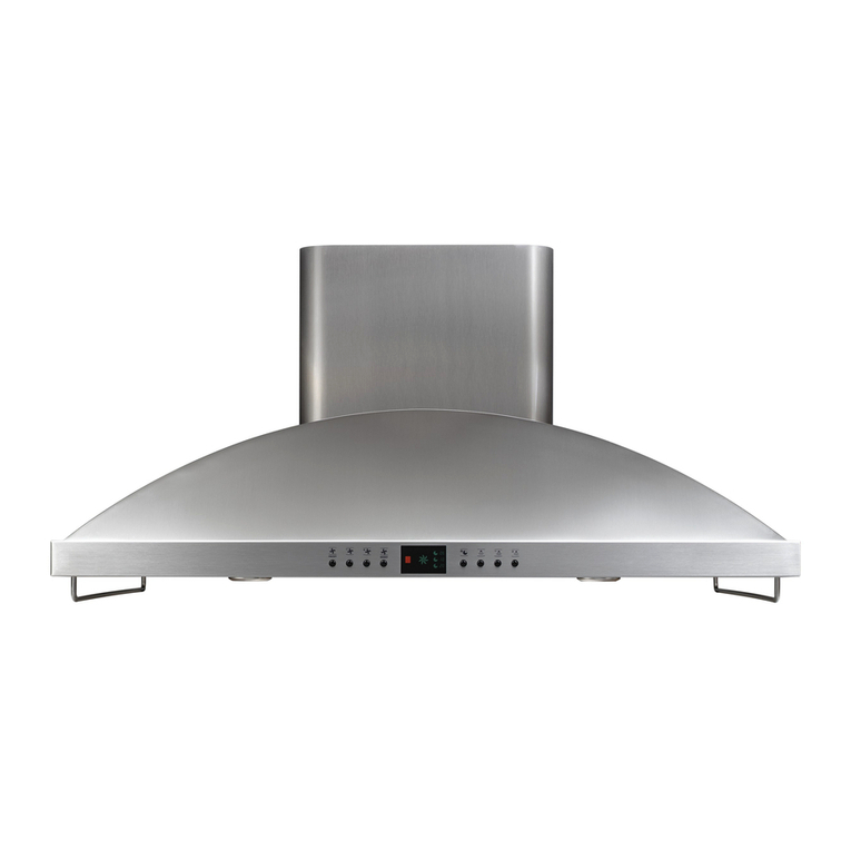
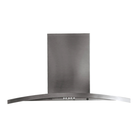
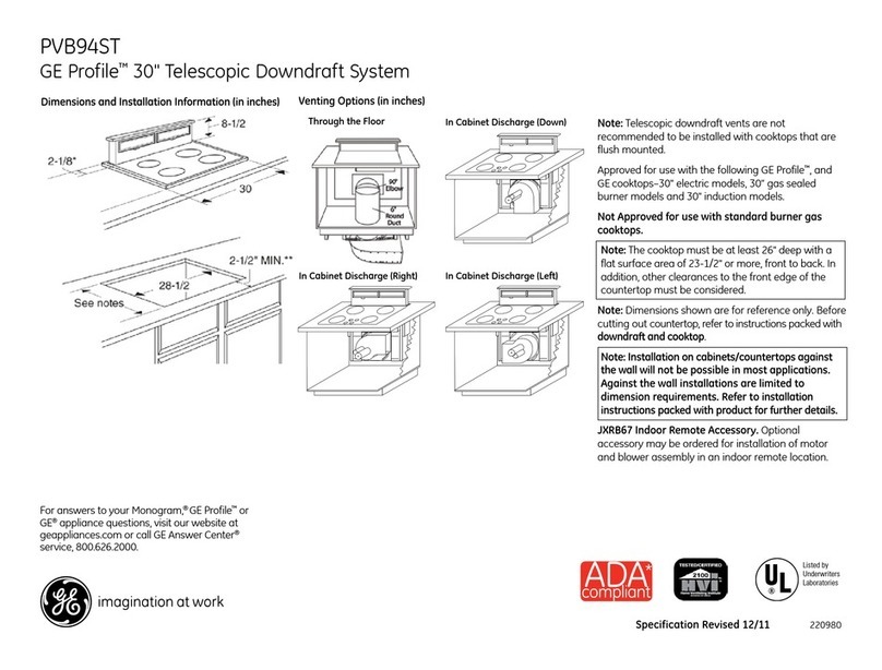
GE Monogram ZVC30LSS User manual

Installation
Instructions
30″, 36″ and 48″Custom Hood Insert
ZVC30LSS
ZVC36LSS
ZVC48LSS
49-80415
12-06 JR

2
Installation Instructions
WARNING: T REDUCE THE RISK
F FIRE, ELECTRIC SH CK R INJURY T
PERS NS, BSERVE THE F LL WING:
A. Use this unit only in the manne intended by the
manufactu e . If you have questions, contact the
manufactu e .
B. Befo e se vicing o cleaning unit, switch powe off at
se vice panel and lock the se vice disconnecting means
to p event powe f om being switched on accidentally.
When the se vice disconnecting means cannot be locked,
secu ely fasten a p ominent wa ning device, such as a tag,
to the se vice panel.
AVERTISSEMENT :
P UR RÉDUIRE LE RISQUE D’INCENDIE,
DE CH C ÉLECTRIQUE U DE BLESSURES
C RP RELLES, IL FAUT BSERVER LES REGLES SUIVANTES :
A. Utilisez cet appa eil uniquement de la maniè e p évue
pa le fab icant. En cas de question, consultez le fab icant.
B. Avant tout ent etien, épa ation ou nettoyage, coupez
l’alimentation élect ique au disjoncteu et ve ouillez le
panneau du disjoncteu pou évite la mise sous tension
accidentelle. S’il est impossible de ve ouille le panneau
du disjoncteu , attachez solidement une note de mise en
ga de t ès visible, comme une étiquette, au panneau.
CAUTI N:
Fo Gene al Ventilating Use
Only. Do Not Use To Exhaust Haza dous O
Explosive Mate ials And Vapo s.
ATTENTI N :
Utilisez uniquement
pou une ventilation géné ale. N’utilisez pas pou
évacue des vapeu s ou des maté iaux
dange eux ou explosifs.
WARNING: T REDUCE THE RISK
F FIRE, ELECTRIC SH CK R INJURY T
PERS NS, BSERVE THE F LL WING:
A. Installation wo k and elect ical wi ing must be done by
qualified pe son(s) in acco dance with all applicable codes
and standa ds, including fi e- ated const uction.
B. Sufficient ai is needed fo p ope combustion and
exhausting of gases th ough the flue (chimney) of fuel
bu ning equipment to p event back d afting. Follow the
heating equipment manufactu e ’s guideline and safety
standa ds such as those published by the National Fi e
P otection Association (NFPA), and the Ame ican Society
fo Heating, Ref ige ation and Ai Conditioning Enginee s
(ASHRAE), and the local code autho ities.
C. When cutting o d illing into wall o ceiling, do not damage
elect ical wi ing and othe hidden utilities.
D. Ducted fans must always be vented to the outdoo s.
• Local codes va y. Installation of elect ical connections
and g ounding must comply with applicable codes. In
the absence of local codes, the vent should be installed
in acco dance with National Elect ical Code ANSI/NFPA
70-1990 o latest edition.
BEF RE Y U BEGIN
Read these instructions completely and
carefully.
•IMP RTANT – Save these inst uctions fo local
inspecto ’s use.
•IMP RTANT – Obse ve all gove ning codes
and o dinances.
•Note to Installer – Be su e to leave these
inst uctions with the Consume .
•Note to Consumer – Keep these inst uctions fo
futu e efe ence.
•Skill Level – Installation of this vent hood equi es
basic mechanical and elect ical skills.
•Completion time – 1 to 3 hou s.
• P ope installation is the esponsibility of the installe .
• P oduct failu e due to imp ope installation is not
cove ed unde the Wa anty.
For Monogram local service in your area, call
1.800.444.1845.
For Monogram service in Canada, call 1.888.880.3030.
For Monogram Parts and Accessories, call
1.800.626.2002.
CAUTI N:
Due to the weight and size of these vent
hoods and to educe the isk of pe sonal
inju y o damage to the p oduct, TW PE PLE ARE
REQUIRED F R PR PER INSTALLATI N.
ATTENTI N :
À cause du poids et des dimensions du
ces hottes et pou édui e les isques de
blessu es ou de dommages du p oduit, IL FAUT
DEUX PERS NNES P UR FAIRE UNE INSTALLATI N
C RRECTE.
WARNING:
To educe the isk of fi e o elect ical shock,
do not use this ange hood with any exte nal
solid-state speed cont ol device. Any such alte ation
f om o iginal facto y wi ing could esult in damage to
the unit and/o c eate an elect ical safety haza d.
AVERTISSEMENT :
Pou édui e le isque d’incendie ou de
choc élect ique, il ne faut pas utilise cette
hotte avec un égulateu de vitesse élect onique
exte ne. Toute modification de ce type du b anchement
d’usine peute endommage l’appa eil ou c ée un isque
de choc élect ique.
T REDUCE THE RISK F FIRE, USE NLY METAL
DUCTW RK.

3
Installation Instructions
AVERTISSEMENT : AFIN DE
RÉDUIRE LE RISQUE D’INCENDIE, DE CH CS
ÉLECTRIQUES U DE BLESSURES C RP RELLES,
VEUILLEZ V US C NF RMER AUX REC MMANDATI NS
SUIVANTES :
A. L’installation et le câblage doivent êt e faits pa une ou des
pe sonnes qualifiées et en confo mité à tous les codes et
no mes applicables, y comp is les no mes en matiè e de
coupe-feu.
B. Le ti age d’ai doit êt e suffisant pou pe mett e une
combustion adéquate et l’évacuation pa le conduit
(cheminée) des gaz de l’équipement de combustion afin
de p éveni le efoulement. Confo mez-vous aux lignes
di ect ices du fab icant de l’équipement de chauffage
et aux no mes de sécu ité, comme celles publiées pa
l’association nationale cont e les incendies (National Fi e
P otection Association, NFPA) et l’association amé icaine
des ingénieu s en appa eils de chauffage, de éf igé ation
et de climatisation (Ame ican Society fo Heating,
Ref ige ation and Ai Conditioning Enginee s, ASHRAE),
ainsi qu’aux codes des auto ités de vot e égion.
C. Lo sque vous pe cez ou coupez les mu s ou les plafonds,
p enez soin de ne pas endommage les fils élect iques ni
les aut es appa eils qui y sont dissimulés.
D. Le conduit de la hotte doit toujou s êt e ventilé ve s
l’exté ieu .
• Les codes peuvent diffé e suivant les égions. L’installation
des connexions élect iques et de la mise à la te e doit
se confo me aux codes applicables. En l’absence de code
élect ique, l’installation de l’évent doit se fai e en confo mité
à Ia no me ANSI/NFPA 70-1990 du code national de
l’élect icité (National Elect ical Code) ou à son édition
la plus écente.
CAUTI N:To educe isk of fi e and to
p ope ly exhaust ai , be su e to duct ai outside.
Do not vent exhaust ai into spaces within walls
o ceilings o into attics, c awl spaces o ga ages.
ATTENTI N
:Il faut p end e soin
d’installe un conduit ve s l’exté ieu pou édui e
le isque d’incendie et pouvoi évacue l’ai
co ectement. Il ne faut pas évacue l’ai dans
l’espace ent e les pa ois d’un mu , un plafond ou un g enie ,
un espace sanitai e ou un ga age.
WARNING: T REDUCE THE RISK
F A RANGE T P GREASE FIRE:
A. Neve leave su face units unattended at high settings.
Boilove s cause smoking and g easy spillove s that may
ignite. Heat oils slowly on low o medium settings.
B. Always tu n hood ON when cooking at high heat o when
flambeing food (i.e. C epes Suzette, Che ies Jubilee,
Peppe co n Beef Flambé).
C. Clean ventilating fans f equently. G ease should not be
allowed to accumulate on fan o filte .
D. Use p ope pan size. Always use cookwa e app op iate fo
the size of the su face element.
AVERTISSEMENT : AFIN DE
RÉDUIRE LE RISQUE D’UN FEU DE FRITURE SUR
LA CUISINIÈRE :
A. Ne laissez jamais sans su veillance les éléments de cuisson de
vot e cuisiniè e lo squ’ils sont églés à une tempé atu e élevée.
Les débo dements cause ont de la fumée et les éclaboussu es
de g aisse peuvent p end e feu. Faites chauffe les huiles
lentement à une tempé atu e basse ou moyenne.
B. Mettez toujou s la hotte en ma che lo sque vous cuisinez à
une tempé atu e élevée ou lo sque vous faites flambe des
aliments (p. ex., c êpes Suzette, ce ises jubilé, flambé de bœuf
au poiv e).
C. Nettoyez la hotte de ventilation éguliè ement. Évitez de laisse
la g aisse s’accumule dans la hotte ou le filt e.
D. Utilisez une casse ole de la bonne dimension. Utilisez toujou s
des casse oles et des poêles d’une taille qui co espond aux
éléments de la cuisiniè e.
WARNING: T REDUCE THE RISK F
INJURY T PERS NS IN THE EVENT F A RANGE
T P GREASE FIRE, BSERVE THE F LL WINGa:
A. SMOTHER FLAMES with a close-fitting lid, cookie sheet
o metal t ay, then tu n off the bu ne . BE CAREFUL TO
PREVENT BURNS. If the flames do not go out immediately,
EVACUATE AND CALL THE FIRE DEPARTMENT.
B. NEVER PICK UP A FLAMING PAN—You may be bu ned.
C. DO NOT USE WATER, including wet dishcloths o towels—
a violent steam explosion will esult.
D. Use an extinguishe ONLY if:
1) You know you have a Class ABC extinguishe , and you
al eady know how to ope ate it.
2) The fi e is small and contained in the a ea whe e it sta ted.
3) The fi e depa tment is being called.
4) You can fight the fi e with you back to an exit.
aBased on “KItchen Fi esafety Tips” published by NFPA.
AVERTISSEMENT : AFIN DE RÉDUIRE
LES RISQUES DE BLESSURES C RP RELLES EN CAS
D’UN FEU DE FRITURE SUR LA CUISINIÈRE,
VEUILLEZ SUIVRE LES REC MMANDATI NS
SUIVANTESa:
A. ÉTOUFFEZ LES FLAMMES à l’aide d’un couve cle ajusté,
d’une tôle à biscuits ou d’un plateau métallique, puis éteignez
l’élément chauffant. PRENEZ GARDE DE NE PAS VOUS BRÛLER.
Si les flammes ne s’éteignent pas immédiatement, ÉVACUEZ
LES LIEUX ET APPELEZ LES POMPIERS.
B. NE SOULEVEZ JAMAIS UNE CASSEROLE EN FEU. Vous isquez
de vous b ûle .
C. N’UTILISEZ JAMAIS D’EAU, y comp is de lavettes ou de
se viettes mouillées. Une explosion de vapeu violente pou ait
en ésulte .
D. Utilisez un extincteu SEULEMENT si :
1) Vous savez que vot e extincteu est de catégo ie ABC et
vous savez déjà comment le fai e fonctionne .
2) Le feu est petit et contenu à l’end oit où il a commencé.
3) Les pompie s ont été appelés su les lieux.
4) Vous êtes en mesu e de combatt e l’incendie sachant que la
so tie de secou s se t ouve di ectement de iè e vous.
aRep is du « Kitchen Fi esafety Tips » (conseils en cas d’incendie
dans la cuisine) publié pa la NFPA.
4
Design Information
C NTENTS
Design Information
P oduct Clea ances ..........................................................................4
P oduct Dimensions ....................................................................5–7
Advance Planning
Advance Planning ............................................................................8
Remote Mounting of the Cont ol (Wi ed)..............................8
Powe Supply ......................................................................................8
Duct Fittings ...................................................................................... 9
Installation Preparation
Tools and Mate ials Requi ed ....................................................10
Remove the Packaging ................................................................10
Pa ts P ovided ..................................................................................11
Ductwo k, Wi ing Locations ......................................................12
Const uct Ceiling Suppo t ..........................................................13
Remote Mounting of the Cont ol (Wi ed)......................14–15
Installation Instructions
Step 1, Install Hood Line ............................................................16
Step 2, Connect Elect ical............................................................17
Step 3, Install Inse t Sleeve ........................................................18
Step 4, Install Dampe Plate ......................................................19
Step 5, Install Blowe Moto ........................................................20
Step 6, Connect Wi ing Ha ness ..............................................20
Step 7, Install Filte s ......................................................................21
Step 8, Finalize Installation ........................................................21
PR DUCT CLEARANCES
The vent hood and line assembly must be installed
30″minimum and 36″maximum above the cooking
su face.
N TE: Installation height should be measu ed
f om the cooking su face to the bottom edge
of the metal hood line o cabinet su face.
N TE: UL equi es any combustible su face to be
a minimum of 30″above the cooking su face.
•This hood must be vented to the outdoo s.
•This hood may be mounted onto a wall o installed
ove an island.
•This hood can be installed ove any Monog am
elect ic/gas cooktop o Monog am P ofessional
cooktop o ange of equivalent width.
30″ min.*
36″ max.*
36″ min.

5
Design Information
PR DUCT DIMENSI NS
4″
28-1/2″
21-1/4″
27-1/2″
14″
16-3/4″
25-3/4″
13″
14″
1/2″
1-1/4″
7-1/2″
The bottom edge of the inse t sleeve has a 7/8″
wide flange on the sides and a 1/2″wide flange
on the f ont and back.
Remote Location for the Control
The cont ol may be emoved f om the hood
and installed into a wall o counte top. A 30-ft.
length of wi e is supplied to accommodate most
installations. A blanking plate cove s the opening
when the cont ols a e emoved.
The overall size of the control is 4-1/4″wide and
2-1/4″deep.
We ecommend that the cutout in g anite o othe
ha d su faces be made befo e the counte top is
installed.
7/8″
1/2″
1/2″
The stainless steel line is shipped with each hood
inse t. This non-combustible line p otects the
unde side of the canopy.
Custom Liner
If you a e not using the supplied line , you may
const uct a custom non-combustible line . Use the
supplied line as a template. The opening must be
26″W x 13-3/16″D. 3/4″ thick mate ial must
su ound the opening to allow the sleeve locking
clips to engage. The inse t sleeve inside the cabinet
should be positioned 1/2″f om the ea wall so
that the cente of the 8″duct is 5-1/2″f om the
ea wall.
*Opening
ZVC30
The custom canopy must be sized to fit the insert
sleeve. Construct the canopy with an opening
that is:
26″W x 13-3/16″D
The opening must be const ucted of 3/4″thick
mate ial to allow the sleeve locking clips to
engage.
The Supplied Liner
Dimensions and Specifications (in inches)
utside Dimensions
The Insert Sleeve
13″
1-11/16″
3-11/16″
Control cutout

6
Design Information
PR DUCT DIMENSI NS
4″
34-1/2″
21-1/4″
27-1/2″
14″
16-3/4″
25-3/4″
13″
14″
1/2″
4-1/4″
7-1/2″
The bottom edge of the inse t sleeve has a 7/8″
wide flange on the sides and a 1/2″wide flange
on the f ont and back.
Remote Location for the Control
The cont ol may be emoved f om the hood
and installed into a wall o counte top. A 30-ft.
length of wi e is supplied to accommodate most
installations. A blanking plate cove s the opening
when the cont ols a e emoved.
The overall size of the control is 4-1/4″wide and
2-1/4″deep.
We ecommend that the cutout in g anite o othe
ha d su faces be made befo e the counte top is
installed.
7/8″
1/2″
1/2″
The stainless steel line is shipped with each hood
inse t. This non-combustible line p otects the
unde side of the canopy.
Custom Liner
If you a e not using the supplied line , you may
const uct a custom non-combustible line . Use the
supplied line as a template. The opening must be
26″W x 13-3/16″D. 3/4″ thick mate ial must
su ound the opening to allow the sleeve locking
clips to engage. The inse t sleeve inside the cabinet
should be positioned 1/2″f om the ea wall so
that the cente of the 8″duct is 5-1/2″f om the
ea wall.
*Opening
ZVC36
The custom canopy must be sized to fit the insert
sleeve. Construct the canopy with an opening
that is:
26″W x 13-3/16″D
The opening must be const ucted of 3/4″thick
mate ial to allow the sleeve locking clips to
engage.
The Supplied Liner
Dimensions and Specifications (in inches)
utside Dimensions
The Insert Sleeve
13″
1-11/16″
3-11/16″
Control cutout

7
Design Information
PR DUCT DIMENSI NS
4″
46-1/2″
21-1/4″
1/2″
3-7/8″
7-1/2″
A 1/2″wide flange su ounds the outside edge of
the inse t sleeve.
Remote Location for the Control
The cont ol may be emoved f om the hood
and installed into a wall o counte top. A 30-ft.
length of wi e is supplied to accommodate most
installations. A blanking plate cove s the opening
when the cont ols a e emoved.
The overall size of the control is 4-1/4″wide and
2-1/4″deep.
We ecommend that the cutout in g anite o othe
ha d su faces be made befo e the counte top is
installed.
The stainless steel line is shipped with each hood
inse t. This non-combustible line p otects the
unde side of the canopy.
Custom Liner
If you a e not using the supplied line , you may
const uct a custom non-combustible line . Use the
supplied line as a template. The opening must be
38-3/4″W x 13-3/16″D. 3/4″ thick mate ial must
su ound the opening to allow the sleeve locking
clips to engage. The inse t sleeve inside the cabinet
should be positioned 1/2″f om the ea wall so
that the cente of the 8″duct is 5-1/2″f om the
ea wall.
*Opening
ZVC48
The custom canopy must be sized to fit the insert
sleeve. Construct the canopy with an opening
that is:
38-3/4″W x 13-3/16″D
The opening must be const ucted of 3/4″thick
mate ial to allow the sleeve locking clips to
engage.
The Supplied Liner
Dimensions and Specifications (in inches)
utside Dimensions
The Insert Sleeve
38-1/2″13″
14″
29-1/2″
1/2″
1/2″
1/2″
13″
1-11/16″
3-11/16″
Control cutout
14″
39-1/2″

Advance Planning
ADVANCE PLANNING
Ductwork Planning
•This hood is equipped fo 8″ound ductwo k.
•Dete mine the exact location of the vent hood.
•Plan the oute fo venting exhaust to the outdoo s.
This hood is not designed fo a eci culating
venting ope ation.
•Use the sho test and st aightest duct oute
possible. Fo satisfacto y pe fo mance, duct un
should not exceed 100 ft. equivalent length fo any
duct configu ations.
•Refe to “Duct Fittings” cha t to compute the
maximum pe missible length fo duct uns to
the outdoo s.
•Use igid metal ductwo k only.
•Install a wall o oof cap with dampe at the
exte io opening. O de the cap and any t ansitions
needed in advance.
Wall and Ceiling Framing for Adequate Support
This vent hood is heavy and the cabinet st uctu e
needs to suppo t the weight of the loaded inse t
sleeve. Adequate st uctu al suppo t must be
p ovided in all types of installations.
•Installation will be easie if the vent hood is
installed befo e the cooktop is installed.
Custom Cabinet Frame Planning
•The custom-built canopy should be sized to
accommodate the hood inse t, and ducting
dimensions in the bottom of cabinet should be
26″W by 13-3/16″D fo the 30″and 36″models
and 38-3/4″ W by 13-3/16″D fo the 48″models.
Remote Mounting of the Control (Wired)
•The cont ol can be emotely mounted on the wall
o the counte top.
•It is ecommended that you use a p ofessional
installe fo the counte top cutout.
•It is ecommended that the cutout in a g anite
counte top o othe ha d su face be made befo e
the counte top is installed.
•The cutout needs to be made at least 6 inches
f om the edges of the counte top.
•If mounting in the counte top above a d awe ,
conside ation must be given to the depth of the
cont ol mounting assembly.
•A 30 ft. wi e co d is p ovided. Ca eful conside ation
must be given to the location of the emotely
mounted cont ol.
•It is ecommended that the 4-wi e co d be outed
th ough 1″conduit between the inse t sleeve and
the emote mounting location.
P WER SUPPLY
IMPORTANT - (Please ead ca efully)
WARNING:
FOR PERSONAL SAFETY, THIS APPLIANCE
MUST BE PROPERLY GROUNDED.
AVERTISSEMENT : POUR
DES RAISONS DE SÉCURITÉ, CET APPAREIL
DOIT ÊTRE CORRECTEMENT MIS À LA TERRE.
Remove house fuse o open ci cuit b eake befo e
beginning installation.
Do not use an extension co d o adapte plug with
this appliance. Follow National elect ical codes o
p evailing local codes and o dinances.
Electrical Supply
This vent hood must be supplied with 120V, 60Hz,
and connected to an individual, p ope ly g ounded
b anch ci cuit, and p otected by a 15 o 20 amp
ci cuit b eake o time delay fuse.
• Wi ing must be 2 wi e with g ound.
• If the elect ical supply does not meet the above
equi ements, call a licensed elect ician befo e
p oceeding.
• Route house wi ing as close to the installation
location as possible, in the ceiling o back wall.
• Connect the hood wi ing to the house wi ing in
acco dance with local codes.
• House wi ing must extend to 45″minimum f om
bottom of cabinet in o de to make connection to
hood wi ing.
Grounding Instructions
The g ounding conducto must be connected to
a g ounded metal, pe manent wi ing system, o an
equipment-g ounding te minal o lead on the hood.
WARNING:The imp ope
connection of the equipment-g ounding
conducto can esult in a isk of elect ic
shock. Check with a qualified elect ician o se vice
ep esentative if you a e in doubt whethe the
appliance is p ope ly g ounded.
AVERTISSEMENT :
Le mauvais b anchement du fil de mise
à la te e peut cause un choc élect ique.
En cas de doute, consultez un élect icien qualifié
ou un technicien pou déte mine si l’appa eil est
à la te e.
8

DUCT FITTINGS
Use this cha t to compute
maximum pe missible lengths fo
duct uns to outdoo s.
N TE: Do not exceed maximum
permissible equivalent lengths!
Maximum duct length:
100 foot for 8″round duct
Flexible ducting:
If flexible metal ducting is used,
all the equivalent feet values in
the table should be doubled.
The flexible metal duct should
be st aight and smooth and
extended as much as possible.
DO NOT use flexible plastic
ducting.
N TE: Any home ventilation
system, such as a ventilation hood,
may interrupt the proper flow of
combustion air and exhaust
required by fireplaces, gas
furnaces, gas water heaters and
other naturally vented systems.
To minimize the chance of
interruption of such naturally
vented systems, follow the
heating equipment manufacturer s
guidelines and safety standards
such as those published by NFPA
and ASHRAE.
This Hood Must Use an
8″Round Duct.
9
Advance Planning
Total
Equivalent Quantity Equivalent
Duct Piece Dimensions Length* Used Length
Round, 1 ft.
st aight (pe foot
length)
3-1/4″x 12″1 ft.
3-1/4″x 24″(pe foot
st aight length)
8″ound
90° elbow 17 ft.
8″ound
45° elbow 10 ft.
3-1⁄4″x 10″14 ft.
3-1⁄4″x 12″15 ft.
90° elbow
3-1/4″x 10″8 ft.
3-1/4″x 12″9 ft.
45° elbow
3-1/4″x 10″33 ft.
3-1/4″x 12″36 ft.
90° flat elbow
8″ to 3-1/4″x 10″2 ft.
8″ to 3-1/4″x 12″2 ft.
o 3-1/4″x 10″t ansition 2 ft.
3-1/4″x 10″to 8″2 ft.
3-1/4″x 12″to 8″2 ft.
ound t ansition
8″ to 3-1/4″x 10″7 ft.
8″ to 3-1/4″x 12″6 ft.
t ansition 90° elbow
3-1/4″x 10″to 8″5 ft.
3-1/4″x 12″to 8″5 ft.
ound t ansition 90° elbow
8″ound
wall cap
with dampe 32 ft. with dampe
3-1/4″x 12″wall cap
with dampe 26 ft. with dampe
8″ound
oof cap 44 ft.
3-1/4″x 10″wall cap
w/ dampe 24 ft.
ound oof vent
*Actual length of st aight duct plus
duct fitting equivalent. Equivalent
length of duct pieces a e based
on actual tests conducted by GE
Evaluation Enginee ing and eflect
equi ements fo good venting
pe fo mance with any ventilation
hood.
Total Duct Run

10
Installation Preparation
TOOLS AND MATERIALS REQUIRED
(NOT SUPPLIED)
Pencil and tape measure
Wire cutter/stripper
Step ladder
Wire nuts
Phillips and flat blade
screwdrivers Strain relief
Spirit level
Flashlight
Safety glasses 8″ducting and
caps as needed
Aluminized
duct tape
1/4″pivoting
hex socket
REMOVE THE PA KAGING
AUTION: Wear gloves to protect
against sharp edges.
ATTENTION : Portez des gants pour
éviter les blessures causées par les tranchants.
AUTION: LIFT THE INSE T SLEEVE
OUT OF THE BOX BY G ASPING THE SIDES.
ATTENTION : SOULEVEZ LE
MANCHON INTÉ IEU DE LA BOÎTE EN SAISISSANT
SES CÔTÉS.
1. Open hood carton.
2. emove the liner, foam and cardboard.
3. emove the tape securing the filters to the insert
sleeve, lift the tabs and remove the filters.
4. Unscrew the 5 nuts securing the damper vent
plate assembly, and remove it from the insert
sleeve. Set the 5 nuts and the damper vent plate
assembly aside, as you will be re-installing it later
in the installation process.
5. emove the screws attaching the insert sleeve to
the mounting board. Discard the screws.
6. Grasp the insert sleeve by the outside edges, and
lift straight up and out of the carton.
NOTE: Do not lift the insert sleeve by the blower
motor.
7. emove and properly discard the plastic wrapping.
8. emove the parts box and other packaging.
Electric drill and
appropriate bits
1″conduit (for remote
mounting only)
Gloves
3/8″socket/
nut driver
Knife
Plumb line
Silicone
Needle-nose pliers

11
Installation Preparation
PARTS PR VIDED
Locate the pa ts packed with the hood.
CHECK INSTALLATI N HARDWARE
Count screws/
components. Screws
shown actual size.
Hood liner (packed in
separate carton)
Blanking plate for
remote control
opening*
6 wood
screws for
hood liner 8 wood
screws for
insert
sleeve
5 nuts for damper plate
assembly
(not located in hardware
bag–you must save nuts
when you remove damper
plate from inset hood
while unpacking parts)
Blower motor
(Models ZVC30LSS and ZVC36LSS)
Insert sleeve
Filters
2 wing nuts
with lock
washers for
blower motor
*NOTE: To be used
on custom hood
when controls are
remotely mounted.
Damper plate
Control wall bracket
Control
mounting
plate
2 mounting plate
screws
30 ft. of 4-wire cord
(straight-pinned)
with connector
NOTE: Not for
telecommunications
(telephone) network.
2 wall
bracket
screws
Dual blower motor
(Model ZVC48LSS)
Control
mounting
bracket
6 insert sleeve chassis
plugs, 1 (optional) house
wire hole plug, 2 rubber
grommets, 4 insert sleeve
washers
REM TE M UNTING F THE C NTR L (WIRED)

12
DUCTW RK, WIRING L CATI NS
Dete mine the exact location of the inse t
sleeve. Ma k the exact cente line location.
The ceiling st uctu e must be capable of
suppo ting the weight of the inse t sleeve
(app oximately 100 pounds) and any
inadve tent use contact loads.
•Measu e f om the top of the cooking
su face to the bottom edge of the inse t
sleeve. Add inse t sleeve installation height.
Ma k that location.
•Use a level to d aw a st aight ho izontal
pencil line on the wall.
N TE: House duct should drop to 11-1/2″
above bottom edge of insert sleeve.
Location of house duct is impo tant
because it must align with vent of
dampe plate assembly.
Ceiling ducting:
If ductwo k will vent st aight up to the ceiling:
•Use a level to d aw a cente line st aight up
to the ceiling.
•On the ceiling, measu e 5-1/2″f om
the back wall to the cente line of an
8-1/2″hole.
Wall Ducting:
If ductwo k will vent to the ea :
•Use a level to d aw a cente line st aight
up to the ceiling.
•Measu e at least 16″above the pencil line
that indicates the bottom installation height,
to the cente line of an 8-1/2″dia. duct hole.
(Hole may be elongated fo duct elbow.)
H USE WIRING L CATI N:
•The junction box is located inside the top left
side of the hood.
•Wi ing should ente the back wall at least
15″above the bottom of the inse t sleeve,
and within 6″of the left side of the
cente line.
16″above pencil
line indicating
bottom of hood
5-1/2″from
rear wall to
centerline
30″Min.
36″Max.
installation
height
36″from
floor to
countertop
Wall Installation Preparation
30″Min.
36″Max.
installation
height
36″from
floor to
countertop
Front viewSide view
11-1/2″
4″liner height
11-1/2″
16″above pencil
line indicating
bottom of hood
4″liner height

13
Plan the Location of the Hood and Ductwork
The ceiling st uctu e must be capable of suppo ting the
weight of the inse t sleeve (app oximately 100 pounds)
and any inadve tent use contact loads.
• Use a plumb bob to check the location. The
counte top/cooktop below the inse t sleeve must be
cente ed with the inse t sleeve.
• The inse t sleeve should extend beyond the f ont and
ea edge of the cooking appliance.
• The inse t sleeve in the ceiling must be cente ed left
to ight ove the cooktop.
C NSTRUCT CEILING SUPP RT (for Island Installation)
Island Installation Preparation
Ceiling
Hood
ducting
centerline
Cooktop
Countertop
Front
Front view
Align with
center of
cooktop Side view
30″Min.
36″Max.
installation
height
30″Min.
36″Max.
installation
height

14
Installation Preparation
REM TE M UNTING F THE C NTR L
(WIRED)
WARNING: Disconnect elect ical
powe f om unit befo e beginning emote cont ol
installation. Failu e to do so could esult in pe sonal
inju y o damage to the elect ical cont ols.
AVERTISSEMENT : Il faut
déb anche l’alimentation élect ique de l’appa eil
avant de commence l’installation de la commande
à distance. Il faut suiv e cette di ective pou évite
des blessu es ou endommage les commandes
élect iques.
REM TE L CATI N F R C NTR L
The cont ol can be emoved f om the hood and
installed in a backsplash o counte top.
•A cove plate is p ovided to cove the opening in
the hood when the cont ol is emoved.
•A 30-ft. length of 4-wi e co d is supplied to
accommodate most installations. Because only
30-ft. of co d is p ovided, ca eful conside ation
must be given to the location of the emotely
mounted cont ol.
N TE: Not for telecommunication (telephone)
network.
•The co d must be outed th ough the holes in the
inse t sleeve, and the ubbe g ommets put into
place a ound the co d.
N TE: n the ZVC30 and ZVC36 models, the cord
needs to be routed through the holes in the insert
sleeve before the damper plate is installed.
•Route the co d th ough the conduit to each the
installation location of the cont ol.
1-11/16″
3-11/16″
Control cutout

15
Installation Preparation
REM TE M UNTING F THE C NTR L
(WIRED) (C NT.)
C UNTERT P
1. Cut out opening in the counte top. Cutout
dimensions a e 1-11/16″x 3-11/16″.
2. Loosen the 4 thumbsc ews and emove the cont ol
f om the inse t sleeve. Replace the cont ol with the
blanking plate p ovided.
3. Attach the mounting plate to the back of the
cont ol with the 2 mounting plate sc ews.
4. Pull the 4-wi e co d th ough the opening in the
counte top, and th ough the back of the mounting
b acket.
N TES: Use provided cable or cable designated by
the National Electrical Code, NFPA/ANSI 70, or local
codes. Not for telecommunication (telephone)
network.
5. Connect the 4-wi e co d to the jack of the
connecto on the cont ol.
6. P ess the cont ol fi mly into the mounting b acket
so that the clips engage.
7. Apply silicone a ound the cutout opening.
8. Inse t the cont ol into the cutout opening.
WALL M UNT
1. Cut out opening into the wall su face. Cutout
dimensions a e 1-11/16″x 3-11/16″.
2. Loosen the 4 thumbsc ews and emove the
cont ol f om the inse t sleeve. Replace the
cont ol with the blanking plate p ovided.
3. Attach the mounting plate to the back of the
cont ol with the 2 mounting plate sc ews.
4. Pull the 4-wi e co d th ough the opening in
the wall, the wall b acket and the back of the
mounting b acket.
N TE: Use provided cable or cable designated by
the National Electrical Code, NFPA/ANSI 70, or local
codes. Not for telecommunication (telephone)
network.
5. Connect the mounting b acket to the wall b acket
using the two wall b acket sc ews. Only sta t the
fi st 1–2 th eads of the sc ews into the wall, as
you want to leave a gap between the two
b ackets to account fo the wall thickness.
6. Raise the tabs on the mounting
b acket so the b acket will fit
th ough the wall opening.
7. Angle the mounting and wall
b ackets and slide them th ough the wall cutout.
N TE: Attach a string to the brackets, so you can
retrieve them from behind the wall if dropped.
8. Flatten tabs on mounting b acket so they a e
flush with the wall su face, and tighten the wall
b acket sc ews to pull the wall b acket flanges
flush with the backside su face of the wall.
9. Connect the 4-wi e co d to the jack of the
connecto on the cont ol.
10. P ess the cont ol fi mly into the mounting
b acket so that the clips engage.
4-wire cord
Mounting bracket
Screws
Connector
Apply silicone around
cutout opening
Mounting plate
Control
4-wire cord
Screws
Jack
Mounting
plate
Control
Wall
bracket
Mounting
bracket
Tabs

16
Installation Instructions
STEP 1 INSTALL H D LINER
1. F ame the cutout opening to fit the line .
N TE: The opening support must be 3/4″thick
wood to accept the liner installation screws.
2. Slide the line up and into the opening until flush
with bottom edges.
3. Secu e the line to the cabinet with 6 sc ews
p ovided.

17
Installation Instructions
STEP 2 ONNE T ELE TRI AL
Verify that power is turned off at the source.
WARNING:If house wiring is not
2-wire with a ground wire, an electrician will need
to convert existing wiring to meet these specs.
When house wiring is aluminum, be sure to
use U.L. approved anti-oxidant compound
and aluminum-to-copper connectors.
AVERTISSEMENT :
Si le câblage de la maison n’est pas un câblage
à deux fils avec un fil de terre, un électricien
doit convertir votre câblage existant à ces
caractéristiques techniques. Si le câblage de votre
maison est en aluminium, assurez-vous d’utiliser
un composé anti-oxydant approuvé et des
raccords aluminium à cuivre.
1. Place insert sleeve on padded, yet stable, surface
below cutout (can use flattened carton to pad
surface).
2. emove the junction box cover.
3. Pull house wires through wall of insert sleeve and
attach the strain relief. Thread the house wire
through the junction box.
4. Connect white leads to branch circuit white lead.
5. Connect black leads to branch circuit black lead.
6. Connect green/yellow leads to branch circuit green
lead.
7. Secure all connections with wire nuts on each
electrical connector.
8. Carefully push wires into junction box and replace
cover.
9. Secure junction box cover with original screws.
Connect
Wires
Screws
Cover

18
Installation Instructions
1. Tuck the house wi ing out of the way.
2. Install the inse t sleeve into the cutout opening of
custom cabinet f ame.
3. Push the inse t sleeve st aight up th ough the
cutout opening until the tempo a y locking clips
engage. The locking clips a e designed to hold the
inse t sleeve in place until it is secu ed with sc ews.
N TE: The locking clips a e not designed to suppo t
all of the weight of the inse t sleeve. Do not leave the
inse t sleeve unattended until sc ews have been
inse ted.
4. Align 8″duct to exhaust opening of inse t sleeve
and seal with aluminum tape.
N TE: House duct should d op to 11-1/2″above
bottom edge of inse t sleeve o the bottom of the
3/4″cabinet base.
5. Tape the 4 washe s in place ove the outside
of the 4 f ont and back holes of the inse t sleeve.
The washe s a e designed to be located between
the inse t sleeve and the 3/4″cabinet su face.
6. P ess the sleeve up fi mly and secu e with the
8 sc ews p ovided. The inse t sleeve should be
flush with the line and have no visible gaps.
N TE: It is IMPORTANT to install f ont mounting
sc ew. The f ont sc ew hole is difficult to see and
may equi e you to place you head into the cutout
opening to locate.
STEP 3 INSTALL INSERT SLEEVE
Clip
Aluminum
tape

19
Installation Instructions
STEP 4 INSTALL DAMPER PLATE
1. Pick up dampe plate assembly and otate so that
vent side is up and b acket is located on left as you
stand facing hood.
2. Inse t dampe plate assembly into inse t sleeve
and ca efully align with 8″house duct.
3. Secu e dampe plate assembly by placing nuts
on bolts and tightening with socket o w ench.
Bolts

20
Installation Instructions
STEP 5 INSTALL BL WER M T R
1. Pick up blowe moto and otate so tabs align
with dampe plate b acket.
2. Inse t blowe moto into inse t sleeve th ough
cutout opening of custom cabinet f ame.
3. Place blowe moto on dampe plate assembly
by sliding blowe moto tabs into slots of dampe
plate assembly.
4. While holding blowe moto in place, lift ight side
so that blowe moto bolt holes align with bolts
p ot uding f om dampe plate assembly and
secu e with lock washe s and wing nuts (hand
tighten).
STEP 6
C NNECT WIRING HARNESS
N TE: On ZVC48, the e a e th ee outing clips and two wi ing ha nesses to connect.
1. Locate both ends of wi ing ha ness.
2. Connect wi ing ha ness by inse ting male into
female opening.
3. Ca efully oute wi ing ha ness and g ound wi e
th ough two clips attached to blowe plate
assembly.
Wiring
harness
Brackets
Other manuals for Monogram ZVC30LSS
4
This manual suits for next models
3
Table of contents
Other GE Ventilation Hood manuals

GE
GE PV976NSS Original instructions

GE
GE JV566 Operating instructions

GE
GE UVW8304 Operating instructions

GE
GE ZVB30ST4SS User manual

GE
GE JV247 Operating instructions

GE
GE Monogram ZVB30 User manual

GE
GE JV960SCBR User manual

GE
GE Monogram ZV750 How to use

GE
GE MONOGRAM ZV800SJSS How to use

GE
GE PVB94STSS Manual