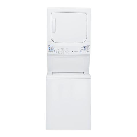
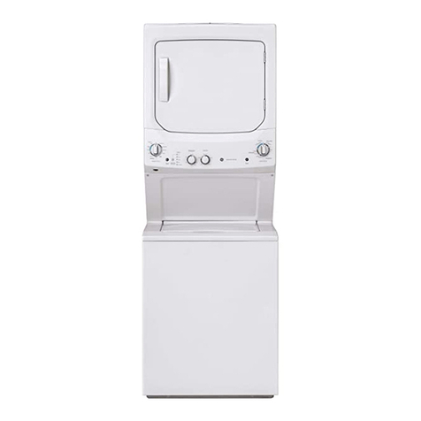
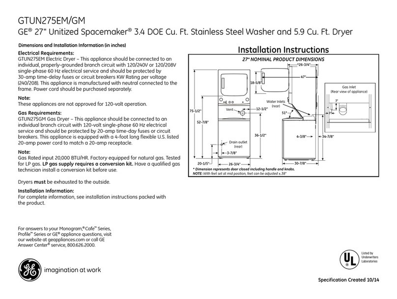
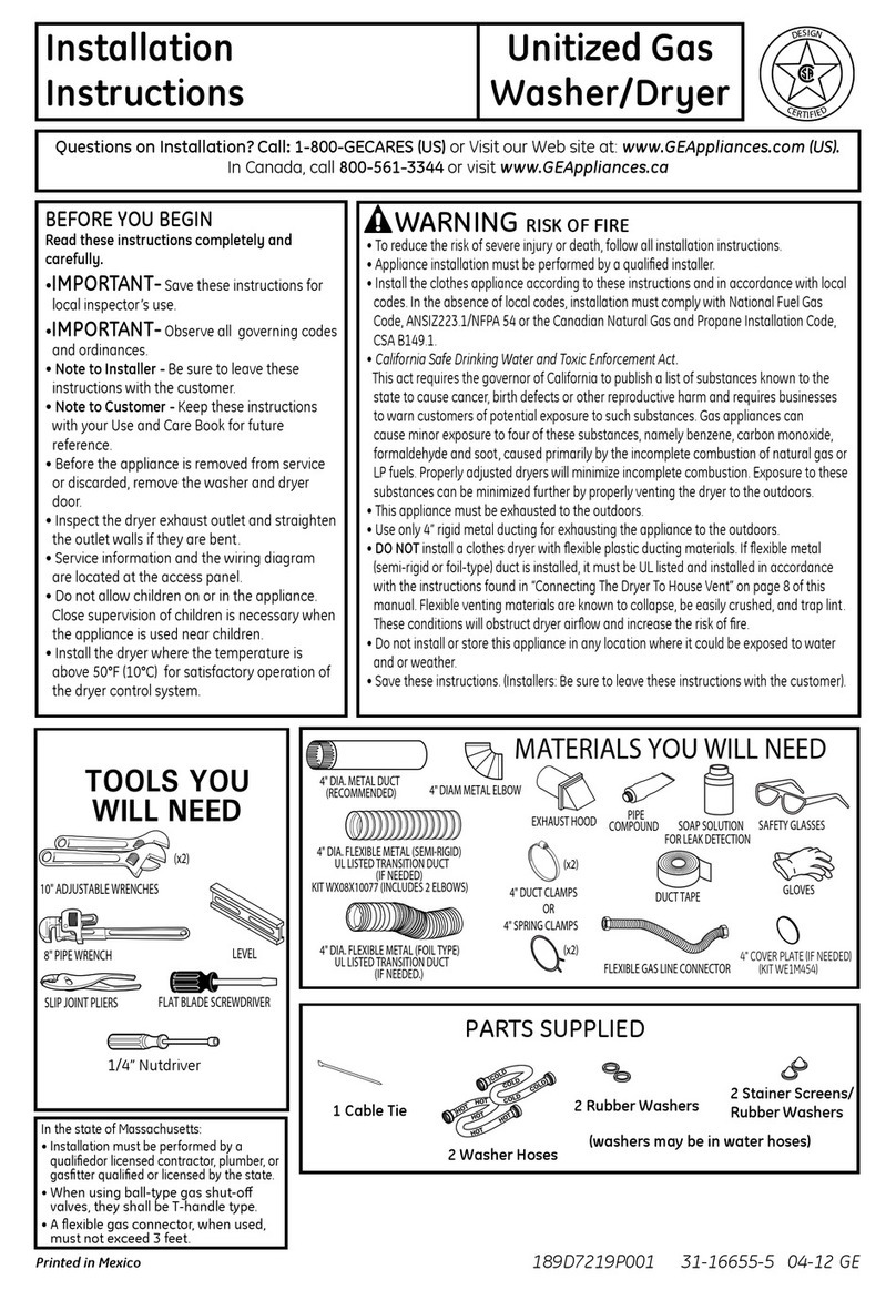
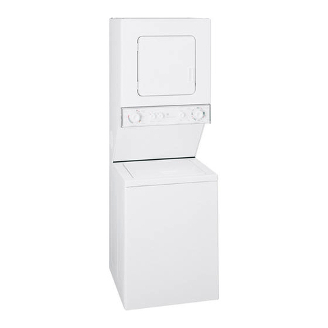
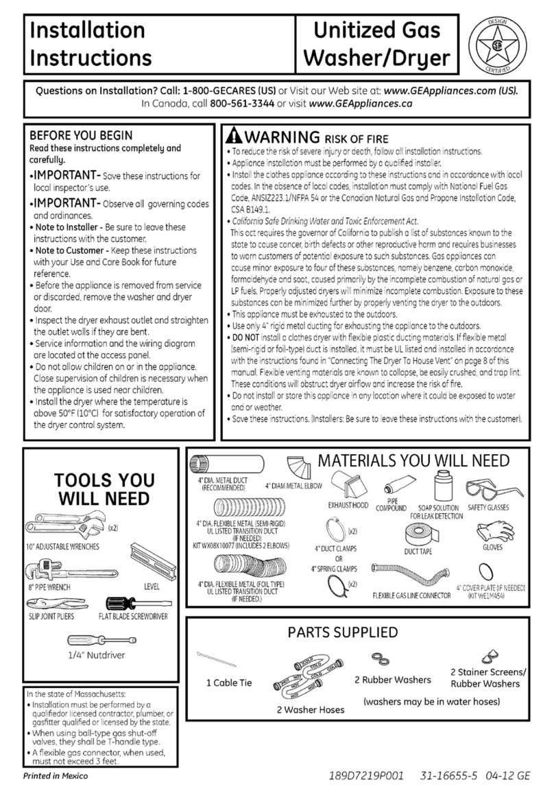
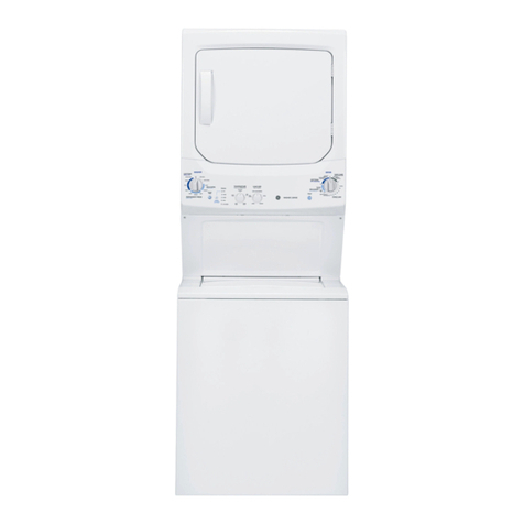
GE GTUP240EM4WW User manual

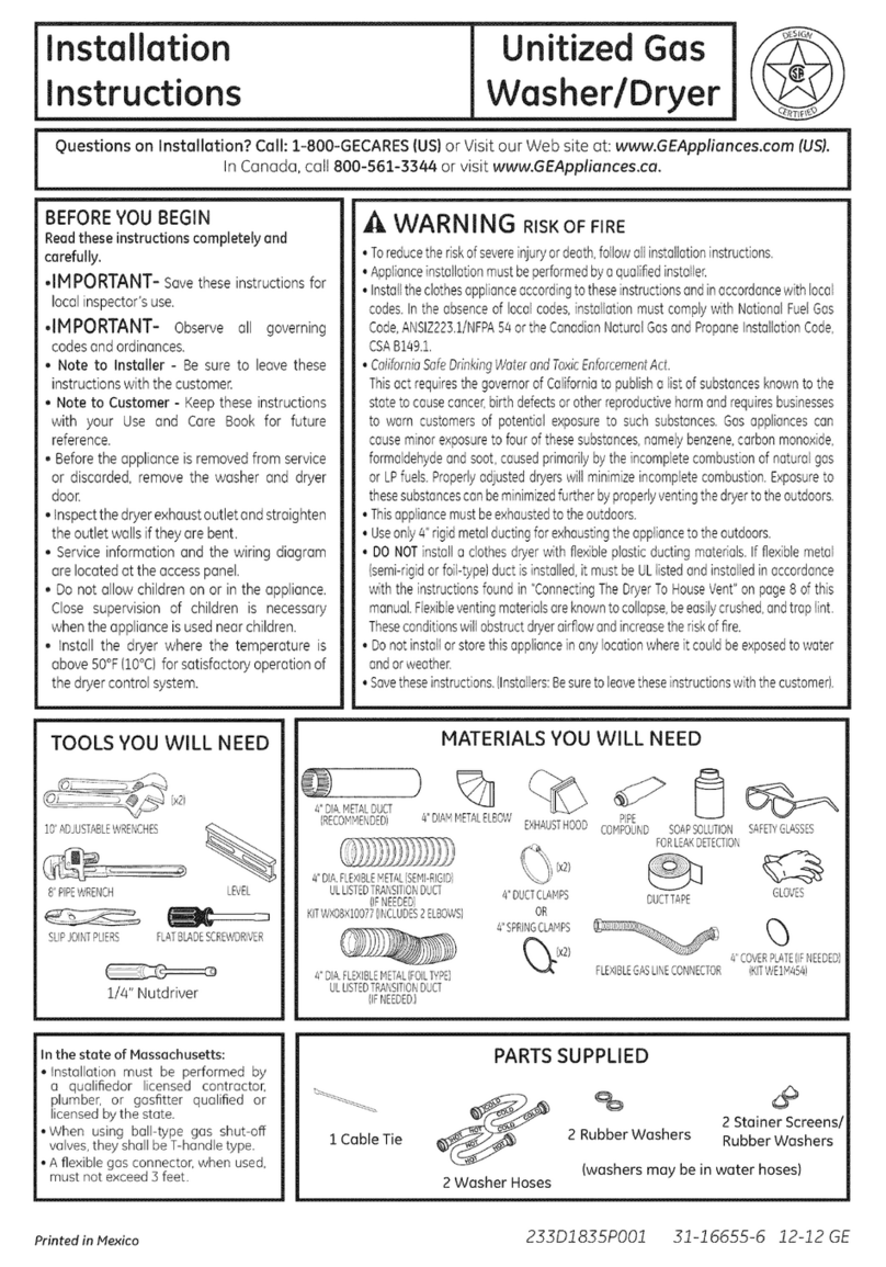
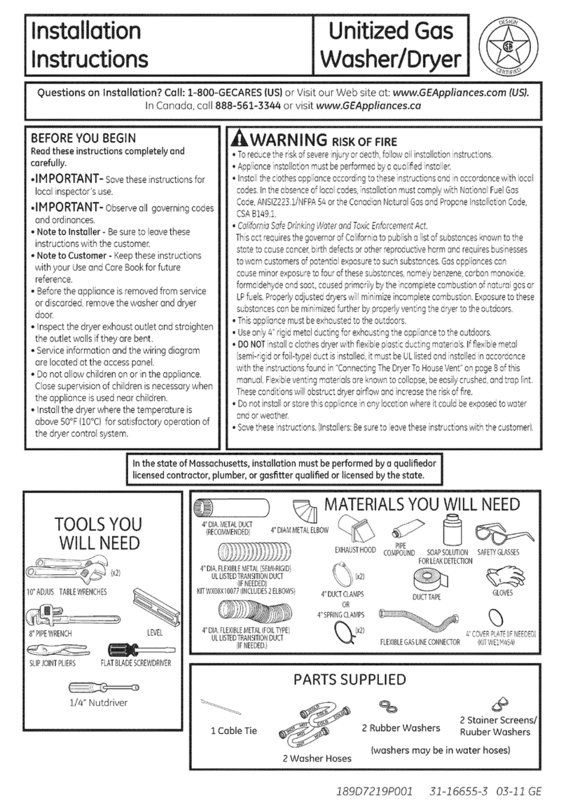
Installation
Instructions Unitized Electric
Washer/Dryer
Questions on installation? Call: 1-800-GECARES {US} or Visit our Web site at: www.GEAppliances.com (US).
In Canada, call 800.561.3344 or visit www.GEAppliances.cu i
BEFORE YOU BEGIN
Readthese instructions completely and
carefully.
• IMPORTANT- savethese instructions for
localinspector's use.
•IMPORTANT- Observe all governing codes
and ordinances.
• Note to Installer -Be sure to leave these
instructionswith the customer.
Note to Customer- Keepthese instructionswith
your Owner's Hanual for future reference.
• Beforethe appliance is removed from serviceor
discarded,remove thewasher and dryer doors.
Inspect the dryer exhaust outlet and straighten
the outlet walls ifthey are bent.
Service information and the wiring diagram are
located at the accesspanel.
Do not allow children on or in the appliance.
Closesupervision of children isnecessarywhen
the appliance isusednear children.
Install the appliance where the temperature is
above 50°F for satisfactory operation of the
control system.
•Productfailure due to improper installation isnot
coveredunder the Warranty.
_LW_KI_I|I_I£_" RISK OF FIRE
. To reduce the risk of severe injury or death, follow all installation
instructions.
Appliance installation must be performed by a qualified installer.
Install the appliance according to these instructions and in accordance
with local codes.
This appliance must be exhausted to the outdoors.
Use only 4" rigid metal ducting for exhausting the clothes dryer to the
outdoors.
DO NOT install a clothes dryer with flexible plastic ducting materials.
If flexible metal (semi-rigid or foil-type) duct is installed, it must be
UL listed and installed in accordance with the instructions found
in "Connecting The Dryer To House Vent" on page 8 of this manual.
Flexible venting materials are known to collapse, be easily crushed,
and trap lint. These conditions will obstruct dryer airflow and increase
the risk of fire.
Do not install or store this appliance in any location where it could be
exposed to water and or weather.
Save these instructions. (Installers: Be sure to leave these instructions
with the customer).
NOTE: installation and service of this appliance requires basic
mechanical and electrical skills, it is your responsibility to
contact a qualified installer to make the electrical connections.
TOOLS YOU WILL NEED
Slip Pliers
Phillips Screwdriver
Flat-blade Screwdriver
1/4" Nutdriver
Level
#' DFA.METALDUCT
(RECOMMENDED/
MATERIALS YOU WILL NEED
#' DUCT
#' DFAFLEXBLEMETAL(SEMFREGED} CLAMPS(2}
ULLISTEDTRANSITIONDUCT
(IFNEEDED} OR
P
KITWXO8XlO077(INCLUDES2 ELBOWS} #' SPRING
CLAMPS(2}
%
#' DIA.METAL
ELBOW
%
EXHAUST SAFETY
HOOD GLASSES
#' DFA.FLEXBLEMETAL(FOELTYPE} _ 3/#'STRAEN
ULLISTEDTRANSITIONDUCT x,4
(iFNEEDED,} DUCTTAPE GLOVES RELIEF
4"COVERPLATE(iFNEEDED/ ULRECOGNIZED
(KiTWE1M454}
APPLIANCEPOWER
CORDKIT
(NOTPROVIDED/
ULRATED
120/2@V,}OA
WITH3 OR4PRONGS,
IDENTIFYTHEPLUG
TYPEASPERTHE
HOUSERECEPTACLE
BEFOREPURCHASING
LiNECORD,
PARTS SUPPLIED
1 Cable Tie % oo
2 Rubber Washers 2 Stainer Screens/
Rubber Washers
(washers may be in water hoses)
2 Washer Hoses
Printedin Mexico 233DI835PO02 31-16652-5 12-12 GE

Installation instructions
INSTALLATION REQUIREMENTS LOCATION
This appliance must be installed on firm flooring to minimize
vibration during spin cycle. Concrete flooring is best, but
wood base is sufficient, provided floor support meets FHA
standards. This appliance should not be installed on rugs or
exposed to weather.
PLUMBING
WATERPRESSURE- Must be 20 psi minimum to 120 psi
maximum.
WATERTEMPERATURE- Householdwater heater should be set
to deliverwater at 120°to !50°F (50°to 66°C)INTHEWASHER
when hot wash isselected.
SHUTOFFVALVES- Both hot and cold shutoffvalves (faucets)
should be supplied.
DRAIN- Water may be drained into standpipe or set tub.
Discharge height MUSTNOTBELESSTHAN30 INCHES,and
no more than 8 feet above the baseof the washer. Standpipe
must be 1-1/2 inches minimum insidediameter and must be
open to atmosphere.
ELECTRICAL REQUIREMENTS
CAUTION: Before plugging in washer, read the following
electrical requirements.
CAUTION: For personal safety, do not use an extension
cord or adapter plug with this appliance. Do not, under any
circumstances, cut or remove the third grounding prong
from the power cord. Follow national electrical codes and
ordinances. This appliance must be supplied with the voltage
and frequency indicated on the rating plate (located at the
top of the dryer front panel),and connected to an individual,
properly grounded branch circuit, protected by a 30-amp
circuit breaker or time-delay fuse. If the electric supply
provided doesnot meet the aboverequirements, calla licensed
electrician.
Step ! Prepare the Area and Exhaust for Installation of
Appliance (seesection !).
Step 2 Check and Ensure the Existing External Exhaust is
Clean (seesection !) and Meets Attached Installation
Specifications (seesection 3).
Step 3 Removethe Foam Shipping Pads (seesection !).
Step 4 Hove the Appliance to the Desired Location.
Step 5 Connect the Power Supply (seesection 2).
Step 6 Connect the External Exhaust (seesection 4).
Step 7 LevelYour Appliance (seesection 5).
Step 8 Connect to plumbing facilities (seesection 8).
Step 9 Check the Operation of the Power Supply
and Venting.
Step !0 Place the Owners Manual and the Installation
Instructions in a Location Where They Will Be Noticed Bythe
Owner.
For Alcove or Closet Installation, see section !0.
For Bathroom or Bedroom Installation, see section !!.
For Mobile or Manufactured Home see, section 9.
For side or bottom exhaust, see section 6.
2

7_._c
Installation Instructions
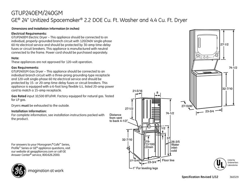
24" NOMINAL PRODUCT DIMENSIONS
51"
!9.1 "J
0ool oo " 0Water Inlets
(rear) _
,_------*23.75"--------_
--- 43"--------€
*Dimension represents door closed including handle and knobs.
NOTE:With feet set at mid position, feet can be adjusted +_.375".
Gas Inlet
(Rearview of appliance)
27" NOMINAL PRODUCT DIMENSIONS
52.9"
0oolo o , 0
Vent_.Q_..
_._._.. Drain outlet
i (rear)
p3.9"
-_----- 26.8"
4------'26.7"-----_
-- !2.5"
--47"_
Waterlnlets
(rear) 5i_°
36.5" 4.35"
__ m
",_----- 30.85"------_
*Dimension represents door closed including handle and knobs.
NOTE:With feet set at mid position, feet can be adjusted +_575".
Gas Inlet
(Rearview of appliance) [

Installation Instructions
Minimum Clearance Other Than Alcove or Closet Installation
Minimum clearance to combustible surfaces and for air opening are: 0 in. clearance both sides and rear.Consideration must
be given to provide adequate clearance for installation and service.
_-I PREPARING FOR INSTALLATION
OF NEW APPLIANCE
REMOVING LINT FROM WALL EXHAUST
OPENING
• Remove and discard existing plastic or metal foil
transition duct and replace with ULlisted transition duct.
WALL
/
INTERNALDUCT CHECKTHATEXHAUST
OPENING HOODDAMPEROPENS
ANDCLOSESFREELV.
TILTTHE APPLIANCE
SIDEWAYS AND REMOVE
THE FOAM SHIPPING PADS
BY PULLING AT THE SIDES
AND BREAKING THEM
AWAY FROM THE APPLIANCE
LEGS.BE SURE TO REMOVE
ALL OF THE FOAM PIECES
AROUND THE LEGS.
After the machine is in the
home, remove remaining
packing material/carton from
washer.
DO NOT REMOVE SHIPPING
RODAT THISTIME.
Remove styrofoam block.
Remove the bag containing
the Washer hoses and parts
parts from tub. Putstyrofoam
block back in tub opening to
hold tub in place during the
rest of installation.
Hove washer close to final
position. Make sure there is
at least a 24" clearance on
right sideof washer to remove
shipping bar. PULLSHIPPING
BAR OUT USING YELLOW
PLASTICHANDLE.Keepbar so
it can be reinstalled if washer
isever moved again.
Styrofoam BlocJ_
Washer hoses
and parts II I
Shipping
Bar
Yellow plastic handle
4
NEW HOME OR REMODELING FAUCETS/
DRAI N STANDPIPEIELECTRICAL LOCATION
Right side of
Laundry Center.
.................. _|
Locate spigots, "
drain standpipe ss" |
and electrical plug | 1
in this area
!FLOOR
[] ELECTRICAL CONNECTION INFORMATION
A WAR N IN G -TOREDUCETHERISKOF
FIRE,ELECTRICALSHOCK AND PERSONAL INJURY:
• DO NOT USE AN EXTENSION CORD OR AN
ADAPTER PLUG WITH THIS APPLIANCE.
Thisdryer must be electrically grounded in accordance
with local codes,or inthe absence of local codes,with the
National ElectricalCode,ANSI/NFPANO.70 or Canadian
ElectricalCode,CSAC22.1.
ELECTRICAL REQUIREMENTS
This appliance must be connected to an individual
branch circuit, protected by the required time-delay
fuses or circuit breakers. A four or three-wire, single
phase, 120/240V or 120/208V, 60Hz, 30 amp circuit
is required. If the electric supply does not meet the
above specifications, then call a licensed electrician.
GROUNDING INSTRUCTIONS
a. For a grounded, cord-connected appliance:
This appliance must be grounded. In the event of
malfunction or breakdown, grounding will reduce
the risk of electric shock by providing a path of
least resistance of electric current. This appliance is
equipped with a cord having an equipment-grounding
conductor and a grounding plug. The plug must be
plugged into an appropriate outlet that is properly
installed and grounded in accordance with all local
codes and ordinances.
WARNING -Improper connection of the
equipment-grounding conductor can result in a risk
of electric shock. Check with e qualified electrician
or servicemen if you are in doubt us to whether the
appliance is properly grounded.

Installation
GROUNDING INSTRUCTIONS {Cont.}
Do not modify the plug provided with the appliance. If it
will not fit the outlet, have a proper outlet installed by a
qualified electrician.
B.Fordirect-wire connected appliance:
This appliance must be connected to a grounded, metal,
permanent wiring system, or an equipment-grounding
conductor must be run with the circuit conductors and
connected to the equipment grounding terminal or lead
on the appliance.
ELECTRICAL CONNECTION LOCATION
24" MODELS 27" MODELS
CONNECTING DRYER USING 3-WIRE
CONNECTION GREEN GROUND
GROUND STRAP
SCREW NOT
WIRE STRAINRELIEF
BRACKET
3/4",UL
RECOGNIZED
RELIEF
NEUTRAL
(White) HOT
WIRE
] #i0 AWGMINIMUMCOPPER
COVER CONDUCTORSOR220/240V]ORPOWER
SUPPLYCORDKITMARKEDFORUSE
WITHDRYERS&PROVIDEDWITHCLOSED
LOOPORSPADETERMINALSWITH
3-wi re Connection UPTURNEDENDS{NOTSUPPLIED},
Not for use in Canada.
DONOTuse for Mobile Home Installations.
NOTfor use on new construction.
NOTfor use on recreational vehicles.
NOTfor use in areas where local codes prohibit grounding
through the neutral conduction.
1.Turn off the circuit breaker(s) (50 amp) or remove the
dryer's circuit fuse at the electrical box.
2. Be sure the appliance cord isunplugged from the wall.
3. Removethe power cord cover located at the lower back.
4. Install 3/4 in. UL recognized strain relief to power cord
entry hole. Bring power cord through strain relief.
nstructions
5. Connect power cord as follows:
A. Connect the 2 hot lines to the outer screws of the
terminal block (marked L1 and L2).
B.Connect the neutral (white) line to the center of the
terminal block (marked N).
6. Be sure ground strap is connected to neutral (center)
terminal of block and to green ground screw on cabinet
rear.Tighten all terminal block screws (3)securely.
7. Properly secure power cord to strain relief.
8. Reinstall the cover.
_:LVV/AKI_Iil_I_: NEVER LEAVE THE
COVER OFF OF THE TERMINAL BLOCK.
CONNECTING APPLIANCE USING 4-WIRE
CONNECTION {MUST BE USED FOR
MOBILE HONE INSTALLATION}
NOTES:Since January 1,1996, the National Electric code
requires that the new constructions utilize a 4-wire
connection to an electric dryer.
WARN ING:onlya4-conductorcordshallbe
used when the appliance is installed in a location where
grounding through the neutral conductor is prohibited.
Grounding through the neutral is prohibited for the new
branch-circuit installations, mobile homes, recreational
vehicles, and areas where local codes prohibit grounding
through the neutral conduction.
REHOVEGROUNDSTRAP
ANDDISCARDKEEPGREEN
GROUNDSCREW[oF_ WIRE RELOCATEGREEN
GROUNDSCREW
"\_,_ HERE GREENOR
RELIEF
BRACKET
COVER
HOT
WIRE 3/4",UL /_
RECOGNIZED
STRAIN RELIEF
4 #10 AWGMINiMUMCOPPER
CONDUCTORSOR120/240V 30A POWER
SUPPLYCORDKIT MARKEDFORUSE
WITHDRYERS& PROVIDEDWITH
CLOSEDLOOPORSPADETERMINALS
WITHUPTURNEDENDS(NOTSUPPLIED)
1.Turn off the circuit breaker (s)(30 amp) or remove the
dryer's circuit fuse at the electrical box.
2. Be sure the appliance cord is unplugged from the wall
receptacle.
3. Removethe power cord cover located at the lower back.
4. Remove and discard ground strap. Keep the green
ground screw for step 7.
5. Install 3/4 in. ULrecognized strain relief to power cord
entry hole. Bring power cord through strain relief.

Installation instructions
CONNECTING APPLIANCE USING 4-WIRE
CONNECTION (MUST BE USED FOR
MOBILE HOME INSTALLATION} (Cont.}
6.Connect power cord as follows:
A. Connect the 2 hot lines to the outer screws of the
terminal block (marked L! and L2).
B.Connect the neutral (white) line to the center of the
terminal block (marked N).
7.Attach ground wire of power cord with the green ground
screw (hole above strain relief bracket). Tighten all
terminal block screws (:3)securely.
8. Properly secure power cord to strain relief.
9. Reinstall the cover.
JLWf_KI_Iil_I_: NEVER LEAVE THE
COVER OFF OF THE TERMINAL BLOCK.
EXHAUST INFORMATION
WARNING - IN CANADAANDIN
THE UNITED STATES, THE REQUIRED EXHAUST
DUCT DIAMETER IS 4 IN (102ram). DO NOT
USE DUCT LONGER THAN SPECIFIED IN THE
EXHAUST LENGTH TABLE.
Using exhaust longer than specified length will:
, Increase the drying times and the energy cost.
, Reduce the dryer life.
, Accumulate lint, creating a potential fire hazard.
The correct exhaust installation isYOURRESPONSIBILITY.
Problems due to incorrect installation are not covered by
the warranty.
Removeand discard existing plastic or metal foil transition
duct and replace with ULlisted transition duct.
The MAXIMUM ALLOWABLEduct length and number of
bends of the exhaust system depends upon the type of
duct, number of turns, the type of exhaust hood (wall cap),
and all conditions noted below. Themaximum duct length
for rigid metal duct isshown in the following table.
27" DRYER EXHAUST LENGTH
RECOMMENDEDMAXIMUMLENGTH
Exhaust Hood Types
Recommended Use only for short
run installations
_'1DIA
.......
Rigid
Metal
56 Feet
48 Feet
40 Feet
32 Feet
No, of 90 ° Rigid
Elbows Metal
0 42 Feet
1 34 Feet
2 26 Feet
3 18 Feet
EXHAUST INFORMATION (cont.}
24" DRYER EXHAUST LENGTH
RECOMMENDED MAXIMUM LENGTH
Exhaust Hood Tgpes
Recommended Use onlg for short
run installations
4" DIA
_'d I_ 2 1/2"
No. of 90 ° Rigid
Elbows Metal
0/43 Feet 36 Feet
i 33 Feet 26 Feet
2 24 Feet 16 Feet
, For every additional 90° elbow, reduce the allowable vent
systemlength by 10ft.
, Two 45°elbows will betreated likeone 90°elbow. Forthe side
exhaust installations,add one 90°elbow to the chart.
, Thetotal vent system length includes allthe straight portions
and elbows of the system (transition duct included).
EXHAUST SYSTEM CHECK LIST
HOOD ORWALL CAP
, Terminate in a manner to prevent back drafts or entry of
birds or other wildlife.
, Termination should present minimal resistance to
the exhaust air fiow and should require little or no
maintenance to prevent clogging.
,Never install a screen in or over the exhaust duct. This
could cause lint build up.
, Wall caps must be installed at least 12 in. above ground
level or any other obstruction with the opening pointed
down.
SEPARATIONOFTURNS
For best performance, separate all turns by at least 4 ft.
of straight duct, including distance between last turn and
exhaust hood.
TURNSOTHERTHAN 90°
* One turn of 45oor less may be ignored.
* Two 45oturns should be treated as one 90oturn.
* Eachturn over 45oshould be treated as one 90oturn.
SEALING OFJOINTS
. All joints should be tight to avoid leaks. The male end of
each section of duct must point away from the dryer.
* Donot assemble the ductwork with fasteners that extend
into the duct. They will serve as a collection point for lint.
, Duct joints can be made air and moisture-tight by
wrapping the overlapped joints with duct tape.
, Horizontal runs should slope down toward the outdoors
1/4 inch per foot
INSULATION
Duct work that runs through an unheated area or isnear air
conditioning should be insulated to reduce condensation
and lint build-up.
Installation
[] EXHAUST CONNECTION
, WARNING - TO REDUCE THE
RISK OF FIRE OR PERSONAL INJURY:
. This appliance must be exhausted to the outdoors.
. Use only 4" rigid metal ducting for the home exhaust
duct.
, Use only 4" rigid metal or UL-listed flexible metal
(semi-rigid or foil-type) duct to connect the dryer to the
home exhaust duct. It must be installed in accordance
with the instructions found in "Connecting The Dryer
To House Vent" on page 8 of this manual.
. Donot terminate exhaust in a chimney, a wall, a ceiling,
gas vent, crawl space, attic, under an enclosed floor,
or in any other concealed space of a building. The
accumulated lint could create a potential fire hazard.
, Never terminate the exhaust into a common duct with
a kitchen exhaust system. A combination of grease
and lint creates a potential fire hazard.
, Do not use duct longer than specified in the exhaust
length table. Longer ducts can accumulate lint,
creating a potential fire hazard.
, Never install a screen in or over the exhaust duct. This
will cause lint to accumulate, creating a potential fire
hazard.
, Do not assemble ductwork with any fasteners that
extend into the duct. These fasteners can accumulate
lint, creating a potential fire hazard.
, Do not obstruct incoming or exhausted air.
, Provideanaccessfor inspectionandcleaningoftheexhaust
system,especiallyat turns andjoints. Exhaustsystemshall
be inspectedand cleanedat leastonceayear.
THIS DRYER COMES READY FOR REAR
EXHAUSTING. IF SPACE IS LIMITED, USE
THE INSTRUCTIONS IN SECTION 6 TO
EXHAUST DIRECTLY FROM THE SIDES OR
BOTTOM OF THE CABINET.
STANDARD REAR EXHAUST
Forstraight lineinstallation,connect
the drger exhaustto theexternal
exhausthood usingduct tape or
clamp. EXTERNALDUCT
OPENING
DUCTTAPEOR
DUCTCLAMP
4" METAL DUCTCUT
TO PROPERLENGTH
DUCTTAPEOR
DUCTCLAMP
®
°°i ©© O
nstructions
STANDARD REAR EXHAUST
(Vented above floor level}
AGE
NOTE: ELBOWS WILL PREVENT DUCT KINKING AND COLLAPSING
ELBOW HIGHLY
RECOMMENDED
[5]LEVELINGAND STABILIZINGYOURAPPLIANCE
FRONT-TO-BACK,
[t¢l
2LEVELINGLEGS
Level and stabilizing your appliance
!. Carefully move the appliance to its final location. Gently rock
the appliance into position. It isimportant not to damage the
rubber leveling legswhen moving your appliance to its final
location. Damaged legs can increase appliance vibration. It
may be helpful to spray window cleaner on the floor to help
move your appliance to its final position.
Note: Do not use washer cover to lift the unit.
2.To ensure the appliance is level and solid on all four legs,
tilt the appliance forward so the rear legs are off the
ground. Gently set the appliance back down to allow the
rear legs to self adjust.
3.With the appliance in its final position, place a level on top
of back part of the washer lid and check it side to side,
then check front to back. Screw the front leveling legs up
or down to ensure the appliance is resting solid on all four
legs (no rocking or the appliance should exist), turn the
lock nuts on each leg up toward the base of the unit and
snug with a wrench.
Note: Keepthe leg extension at minimum to prevent excessive
vibration. Thefarther out legs are extended, the more the unit
will vibrate.
7

Installation instructions
CONNECTING THE DRYERTO HOUSEVENT
RIGIDMETALTRANSITIONDUCT
• Forbest drying performance, a rigid metal transition duct is
recommended.
• Rigidmetal transitions ducts reduce the risk of crushing and
kinking.
UL-LISTEDFLEXIBLEMETAL(SEMI-RIGID}TRANSITIONDUCT
• If rigid metal duct cannot be used,then UL-listedflexible metal
(semi-rigid)ducting can beused(KitWX08X10077).
• Neverinstallflexiblemetal duct in walls,ceilings,floors or other
enclosedspaces.
• Total length of flexible metal duct should not exceed 8 feet
(2.4m).
• Formany applications,installingelbows at both the dryerand
the wall ishighlyrecommended(seeillustrations).Elbowsallow
the appliance to sit closeto the wall without kinking and or
crushingthe transitionduct, maximizingdryingperformance.
• Avoidrestingtheduct on sharpobjects.
UL-LISTEDFLEXIBLEMETAL(FOIL-TYPE}TRANSITIONDUCT
• In special installations,it may be necessaryto connect the
dryerto the housevent usinga flexible metal (foil-type)duct.
A UL-listedflexible metal (foil-type)ductmay be usedONLYin
installations where rigid metal or flexible metal (semi-rigid)
ducting cannot be used AND where a 4" diameter can be
maintainedthroughout theentirelengthof thetransitionduct.
• InCanadaandtheUnitedStates,onlytheflexiblemetal(foil-type)
ductsthat complywith the"Outlinefor ClothesDryerTransition
DuctSubject2158A"shallbe used.
• Neverinstallflexiblemetal duct in walls,ceilings,floors or other
enclosedspaces.
• Total length of flexible metal duct should not exceed 8 feet
(2.4m).
• Avoidrestingtheduct on sharpobjects.
• Forbest dryingperformance:
1.Slideoneend ofthe duct overthe clothesdryeroutlet pipe.
2.Securetheduct with a clamp.
3.With the dryer in its permanent position,extendthe duct to
its full length.Allow 2" of duct to overlapthe exhaustpipe.
Cutoff and removeexcessduct. Keepthe duct asstraightas
possiblefor maximum airflow.
4.Securetheduct to the exhaustpipewith theother clamp.
DO
ELBOW HIGHLY
RECOMMENDED
;2
DO NOT USE
EXCESSIVE
DON'T
EXHAUST
8

Installation instructions
_-124" MODELS ONLY:
DRYER EXHAUST TO RIGHT, LEFT OR
BOTTOM CABINET
_WARNING - BEFOREPERFORMING
THIS EXHAUST INSTALLATION, BE SURE
TO DISCONNECT THE APPLIANCE FROM
ITS ELECTRICAL SUPPLY. PROTECT YOUR
HANDS AND ARMS FROM SHARP EDGES
WHEN WORKING INSIDE THE CABINET. BE
SURE TO WEAR GLOVES.
For downward venting, rotate elbow
sections so that elbow points downward
REMOVE
DESIRED
KNOCKOUT
(ONLY1)
ADDING ELBOW AND DUCT FOR
EXHAUST TO LEFT OR RIGHT SIDE OF
CABINET
, Rotate elbow sections so that the opening points to the
sideto which you want to vent. Preassemble 4"elbow with
4" duct. Use only 4" UL approved rigid metal for ducting
inside the dryer.
, Connect duct assembly to the internal elbow.
WARNING- Sesurenottopullordamagethe
electrical wires inside the dryer when inserting the duct,
4" UL approved rigid metal
i DUCT
........ i..[ j ...... TAPE
, Apply duct tape as shown on the joint between the dryer
internal duct and the straight duct pipe.
AWARNING-
Internal duct joints must be
_ ecured with tope, otherwise
they may separate and cause
a safety hazard.
27" MODELS ONLY:
DRYER EXHAUST TO RIGHT, LEFT OR
BOTTOM CABINET
THIS EXHAUST INSTALLATION, BE SURE
TO DISCONNECT THE APPLIANCE FROM
ITS ELECTRICAL SUPPLY. PROTECT YOUR
HANDS AND ARMS FROM SHARP EDGES
WHEN WORKING INSIDE THE CABINET. BE
SURE TO WEAR GLOVES.
For downward venting, rotate elbow
sections so_
EXHAUST TO LEFT OR RIGHT SIDE OF
CABINET
, Rotate elbow sections so that the opening points to the
sideto which you want to vent. Preassemble 4" elbow with
4" duct. Use only 4" UL approved rigid metal for ducting
inside the dryer.
* Connect duct assembly to the internal elbow.
,_ WARNING- Besure not to pull or damage the
electrical wires inside the dryer when inserting the duct.
, Apply duct tape as shown on the joint between the dryer
internal duct and the straight duct pipe.
AWARNING-
H Internal duct joints must be
secured with tope, otherwise
they may separate and cause
a safety hazard.

Installation
If]PLUMBING INFORMATION
WATER SUPPLY REQUIREMENTS
. HOTAND COLDWATERFAUCETS- Must be within 42" of
the appliance water inlet hose connections. The faucets
must be 3/4" garden hose-type so inlet hoses can be
connected.
. WATERPRESSURE- Must be between !0 and 120 pounds
per square inch with a maximum unbalance pressure,
hot vs.cold flowing, of !0 pounds per square inch.
. WATERTEMPERATURE- Water heater should be set to
deliver !20°F (50°C) in the washer when HOT wash is
selected.
, SHUT-OFFVALVES- Both hot and cold water shut-off
valves (faucets) should be supplied.
. LOCATION- Do not install appliance in an area where the
temperature will fall below freezing. If appliance isstored
or transported in freezing temperatures, be sure all water
from the fill and drain systems has been removed.
DRAIN REQUIREMENTS
. DRAIN RATE- The drain or standpipe must be capable
of accepting a discharge at the rate of 16 gallons per
minute.
, DRAINHEIGHT- The drain height must be 33" minimum
and 96" maximum.
. STANDPIPEDIAMETER- The standpipe diameter must
be 1-1/2" minimum. There MUSTbe an air gap around
the drain hose in the standpipe. A snug fit can cause a
siphoning action.
, SIPHONBREAKKIT- Fora drain facility lessthan 33" high,
the hose, coupling and clamps provided in the machine
must be used and, in addition, a siphon break MUSTbe
installed on the back of the machine. Use Siphon Break
Kit WH49X228 and follow instructions in the kit.
Instructions
[8-1CONNECTING TO PLUMBING FACILITIES
Ifnot installed,install rubberwasher in oneendof hotwater hose.
Thread hot water hose onto connection labeled H at top rear
of washer. Handtighten, plus an additional 1/8 turn with pliers.
If not installed, install rubber washer in one end of cold water
hose.Threadcold water hoseonto connection labeled Cat top
rear of washer. Hand tighten, plus an additional 1/8 turn with
pliers.
Moveapplianceasclosetofinal location aspossible,leavingroom
for you to make water, drain, electrical and vent connections to
your home.
NOTE: If longer drain hose
is required, order drain hose
extension kit, part number
WH49X301.Connect additional
drain hose (contained in kit)to
original hose with hose clamp
(contained in kit).
Insertfreeendof drain hoseinto
drain opening of your home up
to drain hose stopper (do not
removehosestopper itprevents
siphoning). If water valves and
drain are built into wall, fasten
drain hose to one of water
hoses with cable tie provided
(ribbed side on inside). If your
drain isa standpipe,fastendrain
hoseto standpipe with cabletie
provided.
10

Installation instructions
[_]MOBILE OR MANUFACTURED HOME
INSTALLATION
. Installation MUSTconform to the MANUFACTUREDHOME
CONSTRUCTION& SAFETYSTANDARD,TITLE 24, PART
32-80 or, when such standard is not applicable, with
AMERICAN NATIONAL STANDARD FOR MOBILE HOME,
ANSl/NFPA NO. 501B.
. The appliance MUST be vented to the outdoors with
the termination securely fastened to the mobile home
structure,
. The vent MUST NOT be terminated beneath a mobile or
manufactured home.
. The vent duct material MUSTBEMETAL.
• KIT14-D346-33MUSTbeusedto attach theappliancesecurely
to the structure.
• Thevent MUSTNOTbe connectedto any other duct, vent, or
chimney.
. Do not use sheet metal screws or other fastening devices
which extend into the interior of the exhaust vent.
. See section 2 for electrical connection information.
[i-0-IALCOVE OR CLOSET INSTALLATION
. If your appliance is approved for installation in an alcove
or closet, it will be stated on a label on the appliance
back.
. TO PREVENTLARGEAMOUNTSOFLINTAND MOISTURE
FROMACCUMULATINGANDTO MAINTAINDRYING
EFFICIENCY,THISMACHINEMUSTBEEXHAUSTED
OUTDOORS.
. Do not install this appliance with lessthan the minimum
clearances shown above.
CONSIDERATION MUST BE GIVEN TO PROVIDE
ADEQUATE CLEARANCES FOR INSTALLATION AND
SERVICE.
AWARNING: DoNOTINSTALLTHIS
APPLIANCEIN A CLOSETWITH A SOLID DOOR.
DOOR VENTILATION OPENING (27" MODELS)
A minimum of 120 square inches of opening, equally divided
at top and bottom, is required. Air openings are required to
be unobstructed when a door is installed. A Iouvered door
with equivalent air openings for the full length of the door
isacceptable.
When louvers or registers are placed in door openings, the
free air openings of the louvers or registers must equal 120
square inches.
DOOR VENTILATION OPENING (24" MODELS)
27" Model
I Sq.In.
/_0/
li: Iit qn
A minimum of 72 square inches of opening is required. Air
openings are required to be unobstructed when a door is
installed. A Iouvered door with equivalent air openings for
the full length of the door is acceptable.
When louvers or registers are placed in door openings, the
free air openings of the louvers or registers must equal 72
square inches.
24,,Model__ Sqln
/Ill ', _Sq .In.
[n7BATHROOM OR BEDROOM INSTALLATION
. The appliance MUST be vented to the outdoors. See
EXHAUSTINFORMATION section 3 & 4.
, The installation must conform with local codes or, in the
absence of local codes, with the NATIONAL ELECTRICAL
CODE,ANSI/NFPA NO. 70.
11

Installation instructions
[] SERVICING
,WARNING- LABEL ALL WIRES PRIOR TO DISCONNECTION WHEN SERVICING
CONTROLS. WIRING ERRORS CAN CAUSE IMPROPER AND DANGEROUS OPERATION
AFTER SERVICING/INSTALLATION.
Forreplacement parts and other information, refer to Owner's Manual for servicing phone numbers.
REGISTERYOUR NEW APPLIANCE TO RECEIVEANY
IIvlPORTANTPRODUCT NOTIFICATIONS.
Please go to www.GEAppliances.com or mail in your
Product Registration Card.
Forquestions on installation, call: 800.626.2000 (US)or
800-56!-3344 (Canada).
12

Instructions
D'Installation Laveuse/S cheuse
Electriques Unifi s
Question sur l'instellotion? Appelez eu 800.561.3344 (Canada)
Ou visitez notre site web: www.electromenogersge.co
AVANT DE COMMENCER
Lisezles instructions compl_tement et ovec
attention.
•11'4PORTANT-Gardezcesinstructionspour
uneutilisationpossiblepar un r@arateur local.
•IMPORTANT- Respectez les normesen
vigueuret ordonnances.
•Note pour I'instoltoteur - Assurez-vous de
laissercesinstructionsavec leclient.
•Note pour le client - Gardezces instructions
avec votre manuel d'utilisation et d'entretien
pour uneconsultationfuture possible.
•Avant que I'appareil soit d@lac_ apres
r_parationou pour _trejet_, enlevezlesportes
dela laveuseet de las_cheuse.
•Contr61ezlessortiesd'_chappementetredressez
I'installationsurlemur sielleesttordue.
•Lesinformationsder@aration et lediagramme
desconduitssont situ_ssurletableaud'acces.
•Emp_chez les enfants d'etre sur ou dons
I'appareil.Une supervisionproche des enfants
estn_cessaireIorsqueI'appareilestutilis_.
• tnstallez I'appareil oO la temp@ature est en-
dessous de 50°F pour un fonctionnement
satisfaisantdu systemede contr61e.
•Toute d6faillance de I'appareil suite _ une
installation incorrecte n'est pas couverte par
la garantie.
AVERTISSEMENT - RIESQUED'INCENDIE
• Pourr_duireJesrisquesde biessuresgrovesou de mort, suivezJesinstructions
d'instaitation.
•L'installationdeI'appareildolt_trefaiteparunepersonnequalifi@.
•InstalJezJ'appareilsetoncesinstructionsetconform_mentauxnormesJocales.
•Cettes@heusedoltavoirunsystemed'@happementversJ'ext@ieur.
•Utilisezseulementdesconduitsrigidesen m@talde 4" pour Jacanatisationde Ja
s_cheuseversl'ext_rieur.
•NEPASinstallerunes@cheuseavecdesconduitsflexiblesenplastique.Silesconduits
flexiblesde m@tal(semi-rigideou en aluminium)sont install@s,ils doivent@treUL
et install@sconform@mentauxinstructionstrouv@sdans<<BranchezLaS@cheuse
AuxConduitsdeJaViaison>>deJapage8 decemanuet.Lesmat@iauxdesconduits
flexiblessont connuspour sefendre,s'@cras@set @tredespi@ges6 peluches.Ces
conditionsferont obstacleaufluxd'airde las@cheuseetaugmenterontles risques
d'incendie.
•N'instaltezpaset n'entreposezpascet appareitdansun endroitoOil pourrait@tre
expos@_ I'eauouau climat.
•Gardezlesinstructions.(l'installateurdolts'assurerdelaissercesinstructionschezle
client).
NOTE: L'installation et la r_paration de cet appareil exigent des
connaissonces basics en m_canique et en _lectrique. C'est votre
responsebilit_ de contocter un instelloteur quolifi_ pour loire les
connexions _lectriques.
OUTILS A UTILISER
Pince
Tourne-vis Croix
Tourne-visPlat
Tourne-vis A Douille 1A"
Niveau
TUYAUEN METAL
DEDIAM 4"
RECOMMENDE)
TUYAUFLEXIBLEENMETAL
SEMI RIGIDE)UL DEDIAM
4" (SINECESSAIRE)KIT
WXO8X!O077 (2 COUDES
INCLUS)
2 PINCESDETUYAU
4" OU 2 PINCES
TENDEUR4"
MATERIAL NECESSAIRE
55
COUDE DEMETAL
DEDIAM/4"
ROULEAUADHESIF
POURTUYAU
CAPUCHON
D'ECHAPPEMENT
5/4" REDUCTEUR
(_ GANTS DETENSION(UL RECONNUE)
TUYAU FLEXIBLEEN METAL
SEMIRIGIDE) ULDEDIAM4" CACHE DE
(SINECESSAIRE) PROTECTION(SI
NECESSAIRE)DE4" LUNETTES
(KITWE1M454) DE SECURITE
CORDON ELECTRtQUE
D'ALtM ENTATtON (NON
tNCLUT)CONVERStON UL
!20/240V, ]0 ° AVEC ]
OU 4 DENTS. tDENTtFtEZ
LETYPE DE PRISE TEL
QUE LE RECEPTACLE
DE LA MAISON L'EXtGE
AVANT D'ACHETER LES
FtLS ELECTR!QUES.
PIECES FOURNISES
__ 2 Rondellesen Rondelles en
! collier en _,,,,_-,.,4_j_ Caoutchouc caoutchouc
plastique "__ (les joints peuvent entre
2 tuyaux de dans les tuyaux a eau)
la laveuse
233D'183£PO02 3J-J6652-£ J2-J2 GE

Instructions d'Installation
CONDITIONS D'INSTALLATION DEL'EMPLACEMENT
Cet appareil doit @reinstall6 sur un solsolidepour minimiser
lesvibrations durant le cycled'essorage. Lesol en b6ton est
meilleur, mais une base en bois est sufFisante.Cet appareil
nedevrait pas 6tre install6 sur untapis ou expos6au climat.
PLOMBERIE
PRESSIONDE L'EAU- Elledolt 6tre de 20 psi minimum et
120 psi maximum.
TEMPERATUREDEL'EAU- le chauffe-eau de votre maison
dolt 6tre configur6 pour distribuer une eau de 120o5 !50°F
(50° 6 66o Ct DANS LA LAVEUSEIorsque I'eau chaude est
s61ectionn6e.
VALVESDE FERIVlETURE- La valve de fermeture d'eau
froide et celle d'eau chaude (robinet) doivent _tre fournies.
DRAINAGE- L'eau peut _tre drain6e par letuyau de rejet 6
1'6goutou par lebac configur6. La hauteur de I'_coulement
NEDOlTPASETREINFERIEUREA 30 POUCES,et pas plus de
8 piedsaudessus de la basede la laveuse.Letuyau de reject
6 I'_gout doit mesurer !-!/2 pouce minimum 6 I'int6rieur du
diam@treet doit @treouverte vers I'ext@ieur.
CONDITIONS ELECTRIOUES
PRUDENCE: Avant de brancher la laveuse, lisez les
conditions @lectriquessuivantes.
PRUDENCE: pour votre propre s6curit6, n'utilisez pas
de rallonge ou d'adaptateur avec cet appareil. Ne coupez
pas ni enlevez la troisi@me dent de la prise 61ectrique
correspondant 6 la masse. Suivez les normes 61ectriques
nationales pour le voltage et la fr6quence indiqu6s
sur la plaque de conversion (situ6e au-dessus de la
s6cheuse sur le tableau avant), et branchez 6 une prise
individuelle,correctement connect6e 6 la terre, prot6g6e
par disjoncteur de 30-amp ou un fusible 6 retardement.
Si I'installation 61ectrique ne r@ond pas aux conditions
ci-dessus, appelez un 61ectricienqualifi6.
Etape
Etape
Etape
Etape
Etape
i Pr@parezla Zone et I'Echappement de
I'installation de I'Appareil (voir section 1).
2 V@ifiez et Assurez I'Echappement Existant Externe
qu'il soit Propre (voir section !) et lesSp6cifications
d'lnstallation Ci-jointes (voirsection 3).
3 Enlevezla Mousse de Rembourrage de Transport
(voir section 1).
4 D6placez I'appareil au Lieu D6sir6.
5 Branchez I'appareil au Courant Electrique (voir
section 2).
Etape 6 Branchez I'Echappement Externe (voir section 4).
Etape 7 Nivelez I'appareil (voir section 5).
Etape 8 Raccordez au syst_me de plomberie (voirsection 8)
Etape 9 V@ifiez le Fonctionnement du Courant Electrique
et la Ventilation.
Etape !0 Placez le Manuel de I'Utilisateur et les
Instructions d'lnstallation dans un Lieu O_ IIs
Seront Trouv6s Par le Propri6taire.
Pour le Renfoncement ou I'lnstallation dans un iVleuble,
voir section 10.
Pour I'installation dans une salle de bain ou une
chambre, voir section !1.
Pour I'installation dans un mobile home, voir section 9.
Pour 1'6chappement de cot6 ou artiste, voir section 6.
2

Instructions d'Installation
.5'
51"
0°400 ° 0
!9.! ''j
*Dimensions Iorsque los portes sont ferm_es incluont los poign_es et los boutons.
NOTE:Dimensions en pieds, correspondont 5 +_375".
Entr#e du gaz
Vue de I'orri#re de I'opporeil)
2.75"
)U
DIMENSiONES NOMINALES DU PRODUIT 27"
O_1 o o ° O
Ventilation ,____
___..
Sortie drainage
__ urri_re
_-- 3.9"
_---- 26.8"
Arriv_e d'eau
_------'26.7"----_
--47"_
Entr#e du gaz
Vue de I'orri_re de I'opporeil)
3"
*Dimensions Iorsque les pores sont ferm_es incluent les poign_es et les boutons
NOTE: Dimensions en pieds, correspondont 5 +_375".
3

Instructions d'Instollotion
Espace Minimum Autre Que le Renfoncement ou l'installation Dons un Meuble
L'espace minimum pour les surfaces combustibles et I'ouverture d'air sont: 0 in. d'espace de chuque cot6 et c_I'arri@e. Les
consid@ations doivent @re donn6es pour fournir un espace ad6quat pour I'installation et la r6paration.
[_]SE PREPARER POUR L'INSTALLATION
D'UN NOUVEL APPAREIL
ENLEVER LESPELUCHES DE L'OUVERTURE
D'ECHAPPEMENT DU MUR
• Enlevez et d_berrussez-vous des feuilles de m@ulet de
plustique du tuyeu de transition et remplucez-le uvec
un tuyuu de transition UL.
MMUR
VERIFIEZQUE LACLE
HAPPEMMENT
OUVRE ETFERME
LIBREMENT
PENCHER L'UNITE VERS
LE COTE ET ENLEVER
LES PROTECTIONS
DE TRANSPORT DE
STYROMOUSSE EN LES
BRISANT VERS L'EXTERIEUR
DES PATTESDE L'UNITE.
S'ASSURER D'ENLEVER
TOUS LES MORCEAUX DE
STYROMOUSSE AUTOURS
DES PATTES.
OUVERTURE
INTERNEDU
TUYAU
Btocde mousse
Apr@sque la machine soitdans votre de potvstvr@ne_
maison,enlevezles mat@iauxrestants
etcartonsde la laveuse.
N'ENLEVEZPASLESBARRESDE
TRANSPORTPOURLEMMOMMENT.
Enlevezleblocdemoussedepolystyrene. Tuyauxde_ _,
Enlevezle sac contenant les Tuyauxde jonction et._. J
jonction et les pi@cesdu bac. IViettezle pi@ces II
bloc de mousse de potystyr@nedans II
I'ouverturedu bac pour tenir le bac en
place durant le reste de I'instaltation.
D6placez la laveuse vers la position .
finale.Assurez-vousqu'ity ait au mains I I
24"d'espace6droite de la laveusepour
enlevertesbarresdetransport.
TIREZLESBARRESDETRANSPORTVERS
L'EXTERIEURUTILISANTLA POtGNEE
JAUNEENPLASTIq)UE.Gardezlesbarres _
aucasoOvousdevriezla r@instalt@ou si
la laveus est d@plac@eplus tard. transport "
Poign6ejaune
en plastique
NOUVELLEMAISON ETROBINETSREMODELES
/LETUYAUDEVIDANGEA L'EGOUT/
EMPLACEMENTELECTRIQUtj" Cot6 droit du
centre de lavage
Localisez le robinet, la .......... |
colonne d'alimentation i"
du drainage et la prise
61ectrique de cette zone
I
T
42"
sot -
2-]INFORMATION SUR LE BRANCHEMENT
ELECTRIQUE
AVERTISSEMENT- POUR
REDUIRE LES RISQUES D'INCENDIE,
DE DECHARGE ELECTRIQUE ET DE
BLESSURE PERSONNELLE:
, N'UTILISEZ PAS DE RALONGE ELECTRIQUE OU
D'ADAPTATEUR AVEC CET APPAREIL.
Cet appareil dolt _tre branch6 c_la terre conform6ment
aux normes locales et ordonnances, ou dans I'absence
de normes locales, conform_ment AUX NORMES
ELECTRIQUES NATIONALES, ANSI/NFPA NO. 70, ou La
Norme 61ectrique canadienne CSA C22.1.
CONDITIONS ELECTRIQUES
Cet opporeil dolt @tre branch@ 6 une prise _lectrique
individueile, prot@g_e per un fusible retordoteur ou
un disjoncteur. T@trophos_ ou triphos_, uniphos_,
120/240V ou 120/208V, 60Hz, circuit de 30 amp est
requis. Si I'instollotion _lectrique ne r_pond pos oux
sp@cifications ci-dessus, alors appelez un _lectricien
quolifi@.
INSTRUCTIONS DE MASSE
A.Pour une mise 6 la terre, de 1'61ectrom6nager
connect@s 6 I'aide d'un cordon:
Cet appareil dolt @tre mis 6 la terre. En cas de
d6faillance ou de panne, la terre r6duira le risque de
choc 61ectrique en fournissant un chemin de moindre
r6sistance du courant @lectrique. Cet appareil est
6quip6 d'un cordon comportant un conducteur de
terre et une fiche de terre. La fiche dolt @trebranch6e
dans une prise appropri@e, correctement install@e et
mise en conformit6 avec tousles codes Iocaux une
des ordonnances.
AVERTISSEMENT - Unemouvoise
connexion du conducteur de terre peut entroTner un
risque de choc @lectrique. Consultez un @lectricien ou
un r@poroteur quolifi@ si vous @tesdons le doute quont
4

Instructions d'Installation
INSTRUCTIONS DE MASSE (suite)
Ne pas modifier la fiche fournie avec I'appareil - si
elle n'entre pas dans la prise, faites installer une prise
ad6quate par un 61ectricien qualifi&
B.Pour des appareils aux ills connect@sdirectement:
Cet appareil dolt _tre reli6 6 une masse m6tallique,
syst@mede cablage permanent ou un conducteur de
terre dolt _tre ex_cut6 avec les conducteurs du circuit
et connect_ 6 la borne de mise 6 la terre ou de plomb
sur I'appareil.
EMPLACEMENT CONNEXION I_LECTRIOUE
PRODUIT24" PRODUIT27"
BOITIER DE
TERMINAL
BRANCHER L'APPAREIL EN UTILISANT
UNE CONNEXION TRIPHASEE
SI NECESSAIRE, SELON LES VJSVERTEDE
NORMES LOCALES, INSTALLEZ [vJiSEA FiXATiON
UNE PRISEA LA TERRE LATERRE
EXTERNE(NONINCLUT)AUNE
MASSEENMETAL,UN TUYAU FIL CROCHET
D'EAU FROIDE OU AUTRES _b SERRECABLE
MASSES DETERMINEES PAR
L'ELECTRICIEN QUALIFIE. _
SERRECABLE
RECONNU
3/j' UL
NEUTRE
(Blanc) FIL
PROTECTION 3# 10AWGMINIMUMCONDUCTEURSDE
CUIVREOU120/240V30ACORDON
ETFOURNITAVECUNEBOUCLEFERMEE
OUDESBORNESDEBASEAVECDES
EXTREMITESRETOURNEES(PASINCLUT),
Connexion a 3 ills
Ne peut pas #tre utilis#e au Canada.
Ne peut pas #tre utilis#e dans une maison mobile.
Ne peut pas #tre utilis#e dans les nouvelles constructions.
Ne peut pas #tre utilis#e dans lesv#hicules r@cr#atifs.
Nepeut pas@treutilis#edans lesr#gionsDOlescodes locaux
interdisent la raise6 la terre par le biaisdu cSbleneutre.
1. Eteignez le disjoncteur (30 amp) ou d6placez le fusible
du circuit de la s@cheuseau boitier @lectrique.
2. Assurez-vous que le cordon @lectrique de I'appareil
soit d@branch@du boitier du mur.
3. Enlevez la protection du cordon @lectriquesitu@eau
dos en bas.
4. Installez le serre-c@ble UL sAin. A I'entr@edu cordon
@lectrique. Amenez le cordon @lectrique par le
serrec@ble.
5. Branchez le cordon 61ectrique de la mani@e suivante:
A.Branchez 2 ills electriques au vis aux extr@mit@sdu
boitier de terminal (marqu@eL1 et L2).
B.Branchez la ligne neutre (blanche) au centre du bloc
de terminal (marqu@eN).
6. Assurez-vous que le fil de la masse est branch@ au
terminal neutre du boitier et 6 la vis verte de mise 6
laterre sur I'arri@redu coffrage. Serrez toutes les vis
desboitiers de terminaux (3)fermement.
7.Assurezla connexion du cordon @lectriqueau serrecable.
8.R@installezle couvercle.
,_ AVERTISSEMENT: NE
JAMAIS LAISSER LE BOITIER DE
TERMINAL SANS LE COUVERCLE.
BRANCHER L'APPAREIL EN UTILISANT
UNE CONNEXION TETRAPHASEE (DOLT
ETRE UTILISEE POUR L'INSTALLATION
DANS LES MOBILES HOMES)
NOTES: Depuis le premierjanvier 1996, la norme Nationale
Electrique exige que les nouveaux appareils utilisent une
connexion tetraphas#e pour une s#cheuse #lectrique.
AVERTISSEMENT: Seulement les
cordons _lectriques tetraphas_s doivent @tre utilis_s
lorsqu'un appareil est install_ dans un lieu ou la masse
passant par un circuit neutre est prohib_e. Les
installations des embranchements de circuit
_lectrique, les mobiles homes, les v_hicules r_cr_atifs,
et les zones o_ les normes locales prohibent le
branchement 6 la masse par un circuit neutre.
CHAUD DEPLACEZLAVIS
VERTEDEMISEA
LATERREICI FILVERT
OUJAUNE
SERRECABLE
PROTECTION
SERRECABLE /_
HO RECONNUsA"UL
4 # iO AWG HINIMUP CONDUCTEURS
DE CUIVRE OU 120/240V 30A CORDON
ELECTRIOUE, KIT MARQUE POUR UTILiSATION
AVEC SECHEUSES ET FOURNIT AVEC UNE
BOUCLE FERHEE OU DES BORNES DE BASE
AVEC DES EXTREHITES RETOURNEES (PAS INCLUT)
1. Eteignez le disjoncteur (30 amp) ou d_placez le fusible
du circuit de la s#cheuse au boitier #lectrique.
2. Assurez-vous que le cordon #lectrique de I'appareil soit
d6branch6 du boitier du mur.
3. Enlevez la protection du cordon #lectrique situ#e au
dos en bas.
4. Enlevez et d_barrassez-vous des tresses de masse.
Gardez la vis verte de mise 6 la terre pour I'#tape 7.
5. Installez le serre-c@bleUL sA in. A I'entr#e du cordon
#lectrique. Amenez lecordon _lectrique par leserrec@ble.
6. Branchez le cordon #lectrique de la mani@e suivante:
A.Branchez 2 ills electriques au vis aux extr#mit@s
duboitier de terminal (marquee L1 et L2).
B.Branchez la ligne neutre (blanche) au centre du bloc
de terminal (marqu#e N).
5

Instructions d'Installation
BRANCHER L'APPAREIL EN UTILISANT
UNE CONNEXION TETRAPHASEE (DOIT
ETRE UTILISEE POUR L'INSTALLATION
DANS LES MOBILES HOMES} {suite}
7.Attachez le fil de la masse du cordon 61ectrique 6
la vis verte de mise 0 la terre (trou au-dessus des
pinces du serre-c_blet. Serrez toutes les vis des
boitiers de terminaux 13tfermement.
8.Assurez la connexion du cordon 61ectrique au
serrec_ble.
9. RGinstallezle couvercle.
AVERTISSEMENT: NE
JAMAIS LAISSER LE BOITIER DE
TERMINAL SANS LE COUVERCLE.
[] INFORMATION D'ECHAPPEMENT
24" LONGUEUR D'ECHAPPEMENT
LONGUEUR MAXIMUM RECOIVilViANDEE
Types de Capuchons d'echappement
Utilise seulement pour les
Installations de petites distances
RECOMMANDEE:
.......I .......
M@al rigide
4S Feet
SS Feet
24 Feet
Node coude M@al rigide
c_900
0 36 Feet
1 26 Feet
2 26 Feet
• Pour chaque coudeadditionnelde 90°, r@duirede !0 piedsla
Iongueurtotalepermisedusyst@medeventilation.
•Deuxcoudesde4S°devront@treconsid@r@scommeun coudede
90°.Pourlaventilationlat@ale,ajouteruncoudede90°autableau.
•La Iongueurtotale du syst@mede ventilationinclut toutes les
portions droites et tousles coudes du syst@me(le tuyau de
transitioninclus).
AVERTISSEMENT - AUCANADA
ETAU× USA, LE DIAMETRE DU TUYAU
D'ECHAPPEMENT REQUISEST 4" (102turn).
N'UTILISEZ PAS DE TUYAU PLUS GRAND QUE
LA TAILLE SPEClFIEE DANS LE TABLEAU DE
LONGUEUR D'ECHAPPEMENT.
En utilisant un tuyua d'Gchappement plus grand que la
Iongueur spGcifiGe,cela:
• Augmentera le temps de sGchage et lesd@enses en
6nergie.
RGduirala durGede vie de la s_cheuse.
Accumulera les peluches, crGant un risque potentiel
d'incendie.
L'installation correcte d'_chappement est VOTRE
RESPONSABILITE.Lesprobl@mesdus _ une installation
incorrecte ne sont pus couverts par la gerantie.
Enlevez et d@barrassez-vous des plastiques existants
ou du tuyau de transition en feuilles de mGtal et
remplacez-le par un tuyau de transition UL.
La Iongueur de tuyau MAXIMUM AUTORISEEet le
hombre de coudes du syst@med'@chappement
dGpend du type de tuyau, du nombre de courbes, du
type du capuchon d'Gchappement (bouchon du mur)
et des conditions prGsent@esci-dessous.. La Iongueur
maximum du tuyau pour lestuyaux nglde en m_tal est
montr@edans le tableau cidessous.
27" LONGUEUR D'ECHAPPEMENT
LONGUEUR MAXIMUM RECOMMANDEE
Types de Capuchons d'echappement
RECOM MAN DEE Utilise seuiement pour les
Installations de petites distances
,__
4" DIA.
I...... 2-1/2"
NOde Coudes M@aJrigide M@al rigide
6 900
0 56 Feet 42 Feet
i 48 Feet 34 Feet
2 40 Feet 26 Feet
3 32 Feet 18 Feet
LISTE DE CONTROLE DU SYSTEME
D'ECHAPPEMENT
CAPUCHONOU GRILLEDU MUR
, Prot#gez la sortie de votre canalisation dans le but
d'#viter les appels d'air ou I'entr#e d'un oiseau et autres
animaux sauvages.
Cette protection devrait prGsenter une r#sistance
minimum au flux d'air #chappement et devrait exiger
peu ou pas de maintenance pour #viter I'encrassement.
, Ne Jamais installez d'#cran dans ou sur le tuyau
d'#chappement. Ceci pourrait conduire 6 la cr#ation
de peluches.
Les grilles du mur doivent _tre install#es au moinsB
12 in. Au-dessus du niveau du sol ou 6 cette distance
au-dessus de n'importe quel autre objet pouvant faire
obstruction 6 cette sortie.
SI_PARATIONDETOURS
Pour une meilleure performance, sGparez tousles
coudesd'au moins 4 ft. De tuyauterie droite, incluant
la distance entre le dernier coude et le capuchon du
syst_me d'#chappement.
COUDESAUTRESQUE90°
, Uncoude de 450 ou mains peut _tre ignor#.
, Deux coudes de 450 devraient _tre trait#s comme un
coude de 90°.
, Chaque coude de plus de 450 devrait _tre trait# comme
un coude de 90°.
SCELLAGEDESJOINTS
, Tousles joints devraient @tre serr#s pour #viter les
fuites. L'extr#mit_ male de chaque section de tuyau dolt
_tre dirig#e vers I'ext@ieur de la s#cheuse.
, N'assemblez pas la canalisation avec des agrafes qui
entrent dans le tuyau. Elles serviront B la cr#ation de
peluches.
, Les joints de tuyaux peuvent _tre faits d'air et de
moisissures en emballant le chevauchement de joints
avec le rouleau adh_sif de tuyau.
Les trajets horizontaux devraient descendre vers
I'ext@ieur de !/4 pouce par pied.
ISOLEMENT
Lacanalisation qui court 5 travers une zone non chauff@e
ou qui est pros de I'air conditionn_ devrait _tre isol_e
pour r_duire la condensation et la creation de peluches.
6

Instructions d'Installation
i-4--IBRANCHEMENT DE L'ECHAPPEMENT
AVERTISSEMENT- POUR
REDUIRE LES RISQUES D'INCENDIE OU DE
BLESSURES PERSONNELLES:
. Cet appareil doit avoir un syst@med'6chappement
vers I'ext@ieur.
, Utilisez seulement de la tuyauterie rigide en m6tal
de 4" pour le tuyau d'6chappement de la maison.
, Utilisez seulement un tuyau rigide en m@talou un
tuyau flexible UL(semi-rigide ou en aluminium)pour
brancher la s6cheuse au tuyau d'6chappement de
la maison. II dolt @treinstall6 conform6ment aux
instructions trouv@ en page 7 de ce manuel sous
"Brancher La S6cheuse au Conduit d'A@ation de la
maison'.
, Ne mettez pas fin @ 1'6chappement par une
chemin6e, un mur, un toit, un conduit de gaz, un petit
espace, un grenier, sous un plancher non ferm6, ou
dans n'importe quel autre espace dissimul@de votre
batiment. La charpie accumul6e pourrait cr6er un
danger potentiel d'incendie.
, Nejamais mettre fin @1'6chappement par un tuyau
commun avec le syst@me d'6chappement de la
cuisine. Unecombinaison de graisses et de peluches
cr6er un risque potentiel d'incendie.
N'utilisez pas de tuyau plus grand que ce
qui est sp6cifi6 dans le tableau de grandeur
d'@chappement. Des tuyaux plus grands peuvent
permettre I'accumulation de peluches et cr6er un
risque d'incendie potentiel.
Ne jamais installer un 6cran dans ou sur le tuyau
d'@chappement. Ceci causera I'accumulation de
peluches, cr6ant un risque potentiel d'incendie.
N'assemblez pas la canalisation avec des agrafes
qui entrent dans le tuyau. Ces agrafes peuvent
cr66s I'accumulation de peluches, cr6ant un risque
d'incendie potentiel.
N'obstruez pas Fairentrant et sortant.
Mettez @disposition un acc@spour inspecter et
nettoyer le syst@med'@chappement, sp@cialement
aux coudes et auxjoints. Lesyst@med'@chappement
devrait @treinspect6 et nettoy6 au mains une lois
par an.
L'ECHAPPEMENT ARRIERE FAIT PARTIE DE CETTE
SECHEUSE. Sl VOTRE ESPACEEST LIMITE, UTILISEZ
LES INSTRUCTIONS DE LA SECTION 9 POUR AVOIR
UN SYSTEME D'ECHAPPEMENT LATERAL OU PAR LE
BAS DU COFFRAGE DE LA MACHINE.
Pourune installationenlignedroite,branchezle
syst_med'@chappementdela s6cheuseau conduit
externed'6chappementenutilisantduscotchou unepince.
OUVERTURE EXTERNE
DU CONDUIT
APPROPRIEE SCOTCH DE
TUYAU OU PINCE
TUYAUEN HETAL 4" COUPE
A LA LONGUEUR
SCOTCH DE TUYAU
OU PINCE
ECHAPPEMENT ARRIERE STANDARD
(Ventil_ au-dessous du niveau du sol)
CONFIGURATION
RECOMMANDEE
POUR MINIMISER _[[[j _
IILES BLOCAGE DE
CANALISATION
COUDE HAUTEMENT
RECOIVilViANDE
7
NOTE: LES COUDES EFIPECHERONT LES NOEUDS ET LES EFFONDREFIENTS
DU CONDUIT.
[] METTRE A NIVEAU ET STABILISER
VOTRE APPAREIL
/ JTRE
NIVEAU DE
L'AVANTA
L'ARRIERE
d
PIEDSDENIV_LEMENT
Mettre _ niveau et stabiliser votre appareil
1. D@lacezprudemmentI'appareilverssapositionfinale.Balancez
avecdouceurI'appareilen position,tl estimportantde ne pas
endommagerlespiedsde nivelementen caoutchoucIorsque
vousd@lacezvotre appareilvers sa positionfinale.Lespieds
endommag@speuventaugmenterlesvibrationsde I'appareil.tl
peut@treutilede pulv@iserun nettoyeurde vitresur lesolpour
aider5d@lacervotreappareilverssapositionfinale.
Note:N'utilisezpaslaprotectiondelalaveusepourporterI'unitd.
2. PourassurerqueI'appareilest5 niveauetstablesursesquatre
pieds,inclinezI'appareilvers I'avantpourque lespiedsarriere
soient bars du sol. Redescendezen douceurI'appareilpour
permettreauxpiedsarri@esdes'ajusterontseuls.
3. Ayant I'appareil 5 sa position finale, placez un niveau au-
dessusau fond du couvercle de la laveuse et v@ifiezde
chaquecot@,puisv@ifiezI'avantet I'arri@e.Vissezlespieds
de nivelementavant pour assurerque I'appareilrestestable
sursesquatre pieds(nebalancezpasI'appareilpour v@ifier
sastabilit@),relevezles@crousdeverrousurchaquepiedvers
la basede I'unit@etassurezavec untourne-5-gauche.
Note: Gardez/'extensiondepied au minimumpour dviter /es
vibrationsexcessives.Plus/espiedssont agrandis,plusI'unitd
a dechancedevibrer.
7

Instructions d'Instollotion
BRANCHER LA SECHEUSE A
L'AERATION DE LA MAISON
TUYAU RIGIDEDETRANSITION EN METAL
• Pour les meilleures performances de s_chage possibles, le
tuyau de transition rigide en m@tales trecommand@.
• Les tuyaux de transition rigides en m@tal r@duisentle risque
d'@crasementet de noeuds.
TUYAU DETRANSITION UL FLEXIBLEEN METAL(SEMI-RIGIDE}
• Sile tuyau rigideen m6tal ne peut pas_tre utitis@,alorsle tuyau UL
flexibleen m@al(semi-rigide)peut@treutilis6(KitWX08X!0077).
• Nejamaisinstallerdetuyauflexibleenm@alau murs,auplafond,aux
sob ou autres espacesferm_s.
• LaIongueurdu tuyau flexibleenm@alne @wait pasexc6d68pieds
(2,4m).
• Pourplusieursapplications,installer descoudes6lafois6la s6cheuse
et au mur est fortement recommand6 (voir illustration ci-dessous).
Lescoudes permettent 6 I'appareitd'etre ptac6 pros du mur sans
faire de noeudset/ou _craserle tuyau de transition, maximisantles
performancesde s@chage.
• Evitezde pauserle tuyau durdesobjets coupants.
LE TUYAU DE TRANSITION UL FLEXIBLE EN METAL
(ALUMINIUMI
• Pour des installations sp@ciales, il peut @tre n@cessaire de
brancher la s@cheuse6 I'a@ation de la maison utilisant un
tuyau flexible en m@tal (aluminium). Un tuyau UL flexible
en m@tal (semi-rigide) ne peut pas@treutilis@ET ceci o0 un
diam_tre de 4" peut @tremaintenu tout au long du tuyau.
,, Au Canada et aux USA,seulement lestuyaux flexiblesen m@tal
(aluminium) qui se plient 6 <<Description G@n@raledu Tuyau
de Transition de la Laveuse de V@ements du Sujet 2158A >>
devrait @treutilis@.
,, Nejamais installer de tuyau flexible en m@talsur lesmurs, les
plafonds, les sob ou autres espaces ferm@s.
,, La Iongueur du tuyau flexible en m@talne devrait pasexc@d@e
8 pieds (2,4m).
,, Evitez de pauser le tuyau dur des objets coupants.
• Pour les meilleures performances possibles:
!. Fakes glisser une extr@mit@du tuyau sur leconduit ext@ieur
de la s@cheusede v@tements.
2. Fixez le tuyau avec une pince.
3.Ayant la s@cheuseclans sa position permanente, prolongez
le tuyau vers sa Iongueur maximum. Laissez 2" de tuyau
se chevaucher avec le conduit d'@chappement. Coupez et
enlevez I'exc_s de tuyau. Gardez le tuyau aussi droit que
possible pour maximiser le flux d'air.
/4.Fixez le tuyau au conduit d'@chappement avec I'autre pince.
AIRE
UDESFORTEIVlENT
RECOIVllVlANDES
# L'APPAREILSUR LE
ROP LONG f_L_,_--------_ _J_
I l\ /"'NEPAs ,\
\ bV _,// \ CONTRELE\/
8
This manual suits for next models
3
Table of contents
Languages:
Other GE Washer Dryer manuals

GE
GE GTUN275GM1WW User manual

GE
GE GE Unitized Spacemaker WSM2480T User instructions

GE
GE GUAN275 User manual

GE
GE GTD42EASJWH User manual

GE
GE Spacemaker GTUP240GMWW User manual

GE
GE Mabe MCL2040PSBB User manual

GE
GE GUD27GSSM2WW User manual

GE
GE GUD24 User manual

GE
GE GUD27 User manual

GE
GE Spacemaker GUD37ESMMDG User manual
Popular Washer Dryer manuals by other brands

CORBERO
CORBERO CLSV961422DRYEXC user manual

AEG Electrolux
AEG Electrolux LAVAMAT TURBO 14820 Instruction booklet

Midea
Midea MLC31N5AWW User's manual & installation instructions

Hotpoint
Hotpoint BHWD 129 Instructions for use

SCHOLTES
SCHOLTES SDLE 129 Instructions for use

Beko
Beko HTV 7716 DSW BT user manual