4
How To Use This Manual
This installation manual is designed to guide the installer
through the process of installing and starting conditioners
featuring the AvantaPure series controllers.
This manual is a reference and will not include every
system installation situation. The person installing this
equipment should have:
• Training in the AvantaPure series controllers and
Autotrol brand valves
• Knowledge of water conditioning and how to
determine proper control settings
• Basic plumbing skills
• The directional instructions "left" and “right" are
determined by looking at the front of the unit.
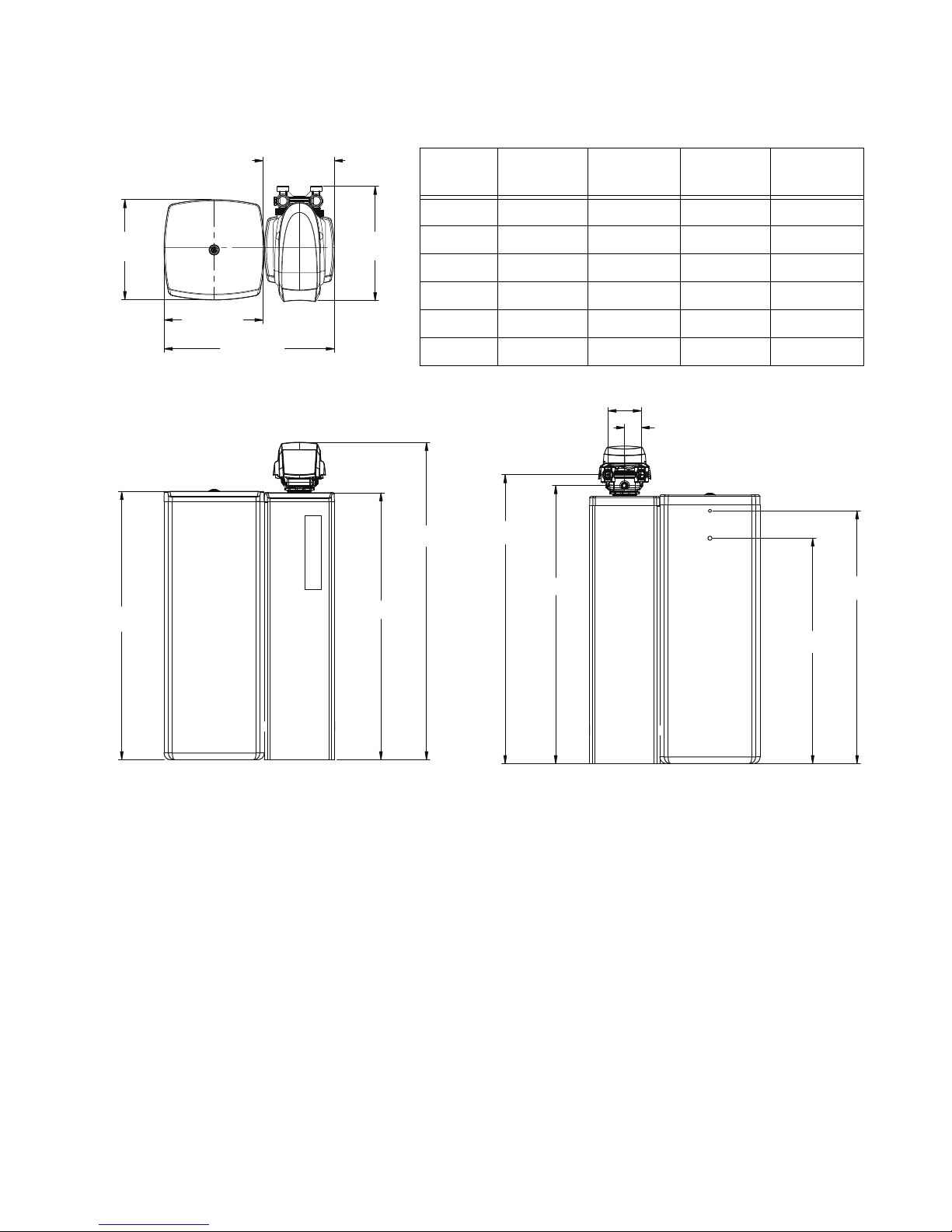
Figure 1
Icons That Appear In This Manual
WARNING:
Failure to follow this
instruction can result in personal injury or
damage to the equipment.
Note:
This will make the process easier if followed.
Introduction
Inspect the unit for damage or missing parts. Contact your
supplier if any discrepancies exist.
Parts Included
•ResinTankwithValve
•BrineTankwithCover
• Power Transformer
• Water Bypass
• Hose Adapter and Flow Control in a bag
• Brine Well Assembly
General Warnings and Safety
Information
Electrical
There are no user-serviceable parts in the AC adapter,
motor, or controller. In the event of a failure, these should
be replaced.
• All electrical connections must be completed
according to local codes.
• Use only the power AC adapter that is supplied.
• The power outlet must be grounded.
• To disconnect power, unplug the AC adapter from its
power source.
Mechanical
• Do not use petroleum based lubricants such as
vaseline, oils, or hydrocarbon based lubricants. Use
only 100% silicone lubricants.
• All plastic connections should be hand tightened.
Teflon tape may be used on connections that do not
use an O-ring seal. Do not use pliers or pipe
wrenches.
• All plumbing must be completed according to local
codes.
• Soldering near the drain line should be done before
connecting the drain line to the valve. Excessive heat
will cause interior damage to the valve.
• Observe drain line requirements.
• Do not use lead-based solder for sweat solder
connections.
• The drain line must be a minimum of 1/2-inch
diameter. Use 3/4-inch pipe if the backwash flow rate
is greater than 7 GPM (26.5 Lpm) or the pipe length is
greater than 20 feet (6 m).
• Do not support the weight of the system on the
control valve fittings, plumbing, or the bypass.
• It is not recommended to use sealants on the threads.
Use Teflonatape on the threads of the 1-inch NPT
elbow, the drain line connections, and other NPT
threads.
• Install appropriate grounding strap across the inlet
and outlet metal piping of the water conditioning
system to ensure that a proper ground is maintained.
WARNING:
Dry location use only, unless
used with a Listed Class 2 Power Supply
suitable for outdoor use.
General • Observe all warnings that appear in this manual.
a. Teflon is a trademark of E.I. duPont de Nemours.