gebatronic Cody Light HF User manual

D
X0509 V1.0
Cody Light HF
Türöffner
Montage, Anschluss und Wartung des Gerätes darf nur von
entsprechend geschulten Fach räften durchgeführt werden.
Hierbei sind die entsprechenden nationalen und lo alen
Vorschriften zu beachten.

Hinweis: Option
Cody Universal Service Tool
Mit Hilfe des Service Tools önnen Sie bequem alle
Programmiereinstellungen vornehmen. Alle A tionen werden Ihnen
omfortabel über ein LCD-Display angezeigt. Zudem haben Sie die
Möglich eit, gezielt Handsender durch Eingabe der jeweiligen
Speicherplatznummer, zu löschen. Nach Betätigung von Handsender
oder nach Eingabe eines gültigen Passiercodes, wird Ihnen der
jeweilige Speicherplatz im Display angezeigt.
00.STU0.00
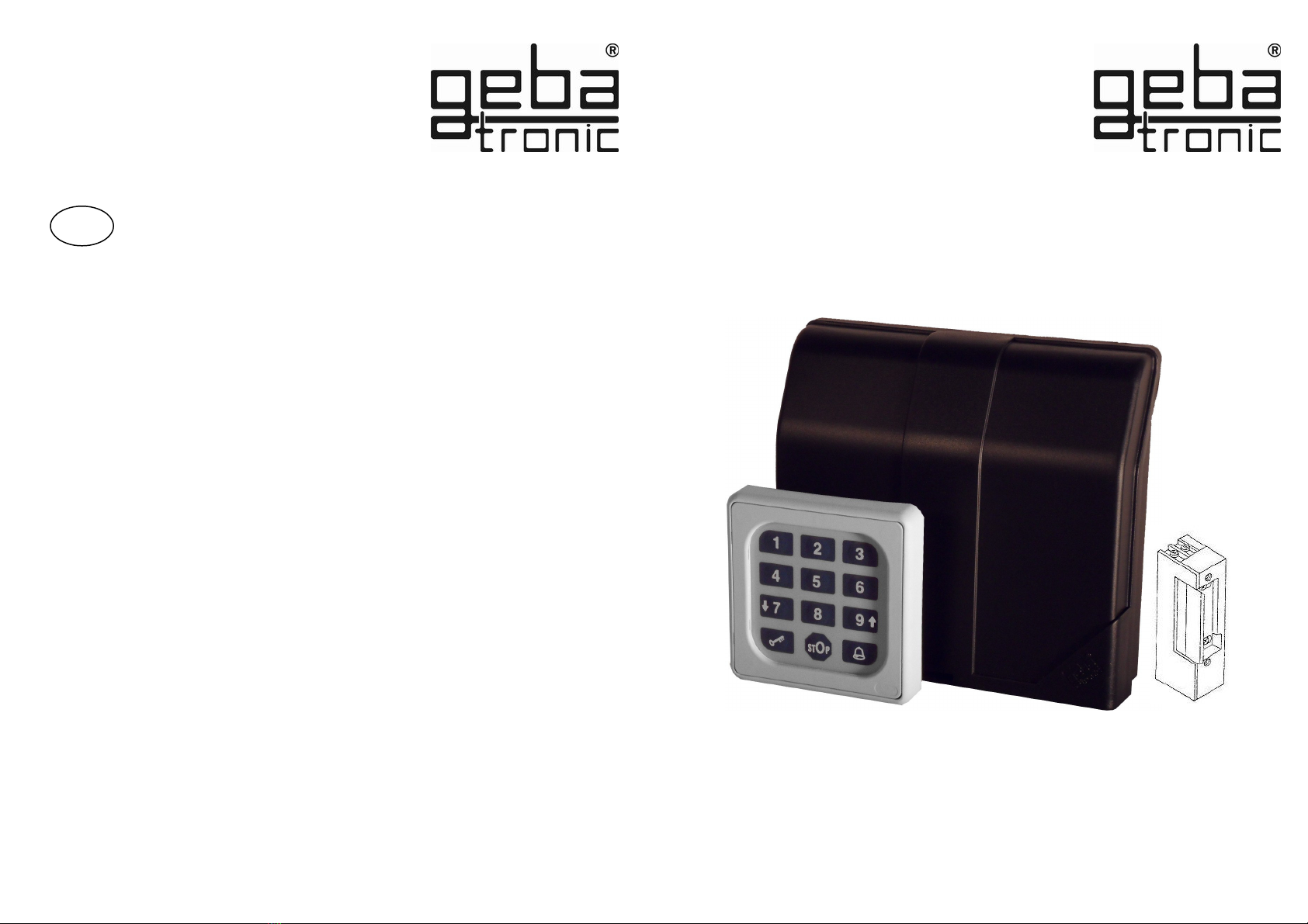
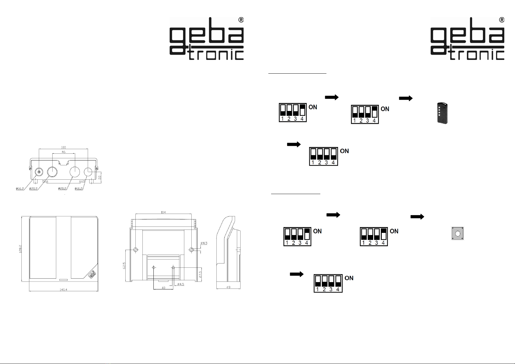
Das Cody Light HF Türöffner besteht aus einer Auswertelogi und
einem Bedienelement. Beide Einheiten werden durch ein
einfaches zweiadriges Kabel ohne Spezialstec er verbunden.
Das Cody Light HF Türöffner ist eine moderne und sichere
Alternative zum her ömmlichen Schlüsselschalter. Bereits nach
dem Programmieren des Passiercodes ist das Cody Light HF
Türöffner einsatzfähig. Zum ansteuern des Türöffners wird
lediglich der vier- bzw. fünfstellige Passiercode eingegeben und
die Schlüsseltaste gedrüc t. Nach orre ter Eingabe des
Passiercodes wird über einen Relais onta t der Türöffner durch
eine Spannung von 12VAC für ca. 5 Se unden betätigt.
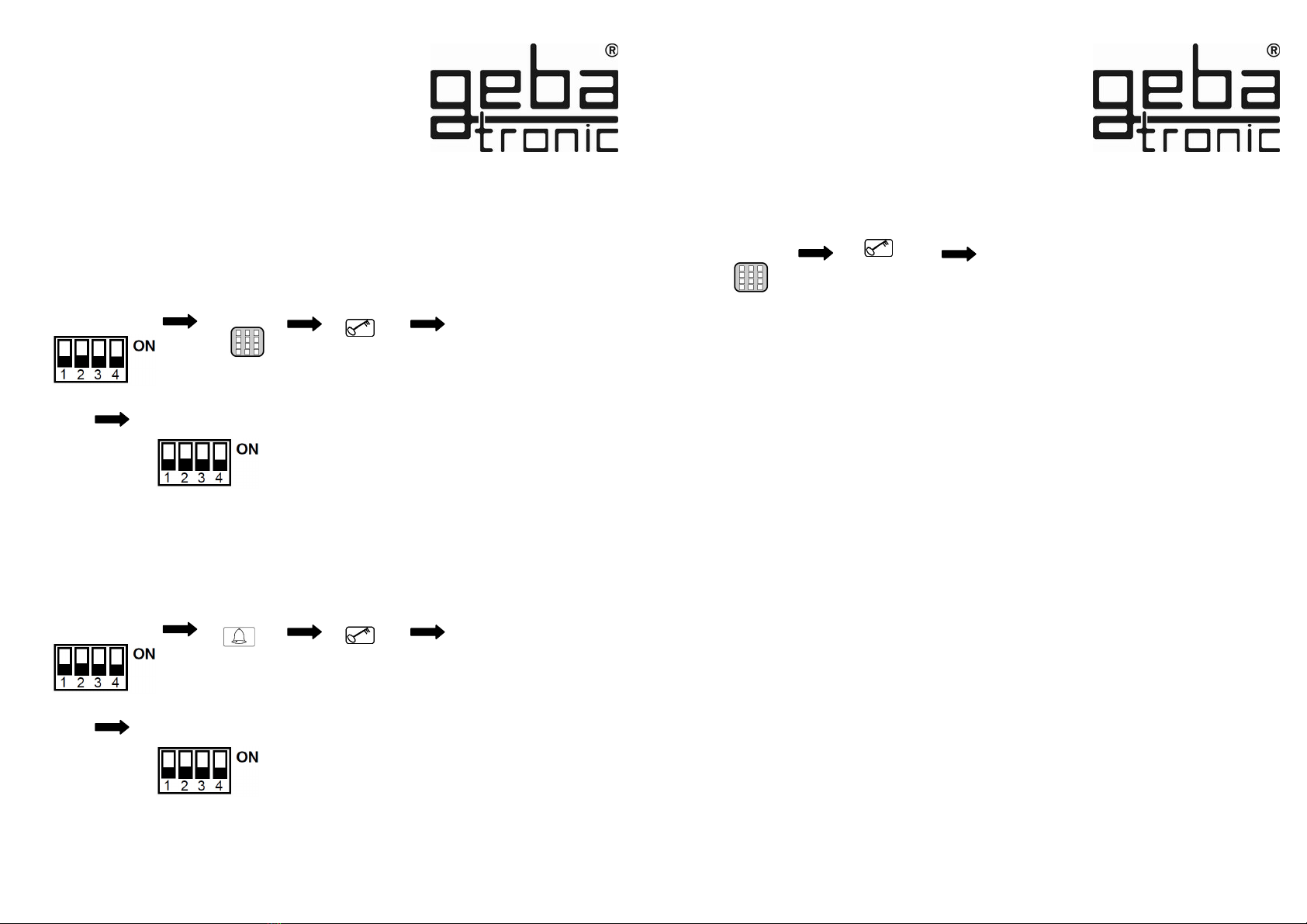
Passiercode:
Der Passiercode ist wahlweise ein vier - oder fünfstelliger
Zahlencode, mit dem Sie Ihren Türöffner betätigen. Sie haben die
Möglich eit, vier unterschiedliche Passiercodes zu speichern.
Sollten Sie bei der Eingabe in Begleitung sein, so önnen Sie vor
der eigentlichen Codeeingabe beliebig viele andere Tasten
drüc en. Somit ist weitestgehend ausgeschlossen, dass sich eine
fremde Person Ihren Passiercode mer en ann.
Das Cody Light HF Türöffner er ennt trotzdem Ihren Passiercode
als orre t an!
Die Eingabe des Passiercodes wird grundsätzlich durch
Drüc en der Taste abgeschlossen.
Gerätebeschreibung

Sperrfunktion:
Aus Sicherheitsgründen ist das Cody Light HF Türöffner nach falscher
Passiercode Eingabe für 20 Se unden gesperrt
(er ennbar an einem Dreifach-Signalton).
Das Ende der Sperrzeit wird durch einen langen Signalton signalisiert
Werkseinstellung (Auslieferungszustand):
Alle Speicherplätze gelöscht
Steuerzeit = 5 se .
Sperrzeit = 20 se .
General-Reset
Die Werkseinstellung sind durch den General-Reset wieder
hergestellt!
DIP 4 auf ON
stellen
Reset-Taste auf
der Logi platine
> 5 se . drüc en
DIP wieder auf
OFF stellen
General-Reset

Der gewünschte Handsender wurde nun gelöscht!
geba GmbH ist von der Gewährleistung und Produ thaftung befreit, wenn ohne unsere vorherige
Zustimmung eigene bauliche Veränderungen vorgenommen werden oder unsachgemäße
Installationen, gegen unsere vorgegebenen Montagerichtlinien, ausgeführt bzw. veranlasst werden.
Der Weiterverarbeiter hat darauf zu achten, dass die EMV-Vorschriften eingehalten werden.
Montageanleitung
Montage der Auswerteeinheit (Innenbereich):
1. Schraubendreher in Schlitz auf Gehäusedec el einstec en, nach oben hebeln und den
Dec el öffnen.
2. Entfernen Sie die Steuerplatine (nur gestec t).
3. Montieren Sie die mitgelieferten Kabel - Verschraubungen in das Gehäuse und stec en
Sie die Platine wieder auf. Achten Sie hierbei auf richtiges Einschnappen der Platine.
4. Bohren Sie die Befestigungslöcher und schrauben Sie den Befestigungsbügel an der
Wand fest.
5. Die Leitung für die Tastatur führen Sie nun durch den lin en Kabel-Eingang
(Dichtnippel) und die Netzleitung durch den rechten Kabel-Eingang. Achten Sie auf dichten Sitz
von Dichtnippel und Kabelverschraubungen, sonst ist der Geräteschutz nicht gewährleistet.
6. Schließen Sie die Leitungen gemäß Anschlussplan an die entsprechenden Klemmen an.
Handsender
Löschen von Handsendern
Montageanleitung
Löschen spezifischer Handsender:
Die eingelernten Handsender wurden alle gelöscht!
DIP 4 auf ON
stellen
zu löschende Taste des
Handsenders > 5 se .
betätigen
Alle DIP auf OFF
stellen
Reset-Taste auf
der Logi platine
> 5 se . drüc en
Alle DIP auf OFF
stellen
DIP 4 auf ON
stellen LED blin t
(2x lang)
Löschen aller Handsender :
DIP 1 auf ON
stellen
DIP 1 auf ON
stellen

Einlernen von Handsendern
Technische Daten
Spannung: 230-240 V AC
Belastung Relaisausgang: 12V AC 800mA
Anschlüsse: 1.5 mm² max.
Temperatur: -20 °C bis +60 °C
Handsender
Stellen Sie vor dem Einlernen sicher, dass das optionale Fun modul auf der Logi platine fest
aufgestec t ist.
Der Handsender wurde eingelernt!!
DIP 4 auf ON
stellen
Gewünschte Taste des
Handsenders
betätigen
Alle DIP auf OFF
stellen
LED blin t
(1x lang)
Netz
230/240VAC
Dieses Produ t entspricht:
EG-Richtlinien Ele tromagnetische Verträglich eit
EN 61000-6-1 08/2002
EN 61000-6-3 08/2002
EG Niederspannungsrichtlinie 2006/42/EG
DIP 1 auf ON
stellen

Codierschalter
Signalton
-lang-
Der neue Passiercode ist jetzt abgespeichert !
Taste
drüc en
Eingabe eines neuen Passiercodes
Codierschalter
Cody Light HF Türöffner
Die vier möglichen Passiercodes werden auf den bar einfache Weise dem Gerät einprogrammiert.
In der Logi einheit befindet sich eine Schalterleiste mit vier DIP-Schaltern (siehe untenstehendes Bild).
Diese vier DIP-Schalter entsprechen den vier Speicherplätzen für die einzelnen Passiercodes.
Vier- bzw. fünf-
stelligen Passiercode
eingeben
Alle DIP auf OFF
stellen
Löschen eines Passiercodes
Der ausgewählte Speicherplatz des Passiercodes
ist nun gelöscht!
Signalton
-lang-
Taste
drüc en
Alle DIP auf OFF
stellen
Taste
drüc en
Signalton
-lang-
Ein korrekter Code wird erkannt; das Relais für den Türöffner zieht
an!
Taste
drüc en
Vor dem eigentlichen Passiercode können beliebig viele andere Tasten gedrückt werden.
Bei Eingabe eines falschen Passiercodes ertönt 3x ein Signalton; die Eingabe eines neuen Codes
ist für die Dauer der Sperrzeit (werksseitig 20 sek.) nicht möglich. Der Ablauf der Sperrzeit wird
durch einen langen Signalton signalisiert.
Eingabe eines Passiercodes
Vier- bzw. fünf-
stelligen Passiercode
eingeben
DIP des
gewünschten
Speicherplatzes
auf ON stellen
DIP des
gewünschten
Speicherplatzes
auf ON stellen

X0509 V1.0
Cody Light HF
door opener
GB
Assembly, connection and maintenance of the device
may only be executed by personnel trained accordingly.
At this the underlying national and local regulations have
to be observed.

The Cody Light HF door opener consists of a decoder and a
control element. Both nits are connected by a simple two-wire
cable witho t a special pl g. The Cody Light HF door opener is a
modern and safe alternative to traditional key switches.
The Cody Light HF door-opener can safely be sed after
programming the pass code.
For driving of the electric-door-lock only a fo r or five digit
n meral code (pass code) has to be entered. After correct inp t
of the pass code and p shing the b tton the drive is
triggered by the 12VAC contact for 5 sec..
Pass code:
The pass code is either a fo r or five digit n meral code, by which
yo operate yo r electric door lock. Yo have the possibility to
store p to fo r different pass codes, which means that p to fo r
persons with individ al pass codes can open the door. If yo are
accompanied by another person when entering yo r pass code
yo can first press as many keys as yo like before yo finally
enter yo r code. This ens res that no other person can
notice yo r pass code.
Device description
Note: Optional Cody Universal Service Tool
The Cody Universal gives yo the possibility to program yo r Cody
Universal conveniently to yo r req irements.
A LCD display shows yo every programming step, incl ding the # of a
sed memory slot, relays settings etc.
It also allows yo to delete RC transmitters directly by their sed
memory slot.
ef. 500.STU0.00

Lock-out function:
If the lock-o t f nction is activated, the Cody Light HF door opener
a tomatically blocks any inp t for a set period (20sec.) after the inp t
of a wrong pass code which is signalled with a (3 beeps) so nd signal.
The end of the blocking time is signalled by a long so nd signal.
General-reset
General reset
P t DIP switch 4 to
ON
P sh reset b tton
on the PCB
> 5 sec.
P t DIP switch
back to OFF
All factory settings are restored by the general reset !
Factory settings (default settings):
all memory slots erased
switching time = 5 sec.
lock-o t time = 20 sec.

The specific transmitter is now deleted !
RC transmitter
Delete specific transmitter:
Program 2
Deleting of remote controls
Press the b tton of the
RC transmitter
> 5 sec.
P t all DIP to OFF
P t
DIP 4 to ON LED flashes
2x long
The taught-in transmitters are now all deleted !
Press the reset
b tton on the
logic board
> 5 sec.
Delete all transmitters:
P t all DIP to OFF
P t
DIP 4 to ON Set DIP 1 to
ON
Set DIP 1 to
ON
geba GmbH is released of its obligations regarding g arantee and prod ct liability if – witho t prior
permission - the nit has been modified, or if the installation is nproper or not in accordance with o r
instr ction man al. The installer has to take care that the EMC-reg lations are respected.
Mounting instructions
Interior mounting of the logic:
1. P t the screw-driver into the gap of the enclos re front, p sh the screw-driver p and
open the enclos re.
2. Remove the control PCB (which is force fitted to the inside of the enclos re).
3. Locate the screwed glands s pplied (sealing nipple left side) in the
enclos re and replace the PCB. (Please ens re PCB is firmly in position)
4. Bore the fastening holes and fix the enclos re bracket at the wall.
5. The wires for the keyboard ens re thro gh the left cable entry (sealing nipple), the wires
for the relay contact thro gh the middle cable entry and the wires for the s pply voltage ens re
thro gh the right cable entry. Ens re tight seating of sealing nipple and cable gland, otherwise the
water-protection of the appliance cannot be ass red.
6. According to connection diagram connect the wires to the corresponding terminals.

230/240VAC
This prod ct complies with:
EC Electromagnetic Compatibility Directives
EN 61000-6-1 08/2002
EN 61000-6-3 08/2002
Low Voltage Directive 2006/42/EC
Technical data
S pply voltage: 230-240 V AC
O tp t: 12V AC 800mA
Connections: 1.5 mm² max.
Ambient temperat re: -20 °C to +60 °C
RC transmitter
Teach-in of remote controls
P t DIP 4 to ON
LED flashes
1x long
P t DIP 1 to
ON
P t all DIP to OFF
The transmitter is programmed!
Press the desired
b tton on the remote
control
Make s re before the teach-in that the optional wireless mod le is pl gged in firmly at the logic board.

Cody Light HF Door-opener ( p to 4 pass code for the relay o tp t)
The fo r possible pass codes are programmed in the easiest way.
There are fo r DIP switches on the logic nit (see pict re below). These fo r DIP switches correspond
to the fo r memory slots for each pass code.
P t DIP of the
desired memoy
slot to ON
Keypad
so nd signal
1x long
Enter 4 or 5
digit pass code p sh
b tton
Entering a pass code
A correct code is detected; the corresponding relay is switched!
Before the actual pass code, you can press any other keys to prevent fraud.
If an incorrect pass code is entered, you will hear a sound signal (3 beeps).
Entering a new pass code is only possible after the lock-out period (factory: 20 sec.) which end is
signalled by a long sound signal.
Creating a new pass code
Keypad
Enter 4 or 5
digit pass code so nd signal
1x long
p sh
b tton
Set all DIP to
OFF
The new pass code is now saved!
P t DIP of the
desired memoy
slot to ON
so nd signal
1x long
p sh
b tton
p sh
b tton
Set all DIP to
OFF
The selected memory slot of the pass code
is now deleted!
Deleting a pass code

E
X0509 V1.0
Cody Light HF
Abrepuertas
El montaje, conexión y mantenimiento de esta unidad
deben ser realizados sólo por personal autorizado.
Las normas, re lamento y estándares locales deben ser
cumplidos por el instalador de esta unidad.

ATENCIÓN: Cody Universal Servi e Tool OPCIONAL
El Cody Universal Service Tool le ayudará a pro ramar su Cody
Universal. Le facilitará la pro ramación de las diferentes posibilidades
racias a la pantalla LCD. Con esta herramienta tiene la posibilidad de
pro ramar o borrar una posición determinada, especialmente indicado
para los mandos a distancia. Una vez introducido un Códi o de
Acceso correcto, o activado el sistema mediante mando a distancia,
en la pantalla le aparecerá la posición en la memoria de ese elemento
en concreto.
500.STU0.00
El Cody Li ht HF Abrepuertas está compuesto de una unidad
ló ica que necesita un elemento de control. Ambas unidades se
conectan mediante un cable bifilar sin necesidad de conexiones
especiales. El Cody Li ht HF Abrepuertas es una moderna y
se ura alternativa para el inversor a llave. Mediante el uso de los
códi os de acceso de 4 o 5 cifras usted puede accionar un
abridor de puertas alimentado a 12VAC que accione durante 5
se undos.
Códi o de acceso:
El códi o de acceso es un códi o numérico de 4 ó 5 cifras que le
permitirá accionar su puerta. Antes de introducir el códi o de
acceso usted puede pulsar tantas teclas como quiera. De esta
forma en caso de no estar solo al introducir el códi o puede
evitar que memoricen el códi o de acceso al verle pulsarlo en el
teclado.
El Cody Li ht HF Abrepuertas reconocerá el códi o de acceso
como correcto.
Tras introducir el códi o de acceso debe pulsar
Des rip ión

Fun ión de bloqueo:
El Cody Li ht HF se bloqueará automaticamente durante veinte
se undos después de pulsar un códi o de acceso falso, (este bloqueo
se reconocerá por un triple pitido). El fin del tiempo de bloqueo se
reconocerá mediante un lar o pitido.
Configura ión de fábri a (Códigos por defe to):
Todas las posiciones en la memoria borradas
Tiempo activación del relé = 5 se .
Tiempo de bloqueo = 20 se .
Reset General
El sistema queda on la onfigura ión de fábri a después
del Reset General
Pon a el DIP 4 en
posición ON Presione
> 5 se . El botón
Reset
Pon a el DIP 4
en posición
OFF
General-Reset

El Mando a Distan ia ha sido borrado.
geba GmbH no concede arantía ni se hace responsable de los productos a los que sin nuestro
consentimiento les fueran efectuadas modificaciones estructurales. La arantía no cubre los daños
ocasionados debido a una instalación inadecuada en contra de nuestras recomendaciones de montaje.
El instalador debe tener en cuenta que se cumplan los re lamentos EMV y locales.
Montaje del Cody Universal (En el interior):
1. Con la ayuda de un destornillador abra la tapa de la unidad.
2. Saque la placa ló ica (está sólo sujeta con las rapas, no atornillada)
3. Monte los prensestopas para los cables conforme el montaje que desee. Fije la placa ló ica de
nuevo mediante presión, debe quedar sujeta con las rapas.
4. Taladre los a ujeros en la pared y atornille el estribo de fijación situado en la parte de detrás de la
unidad.
5. El cable para el teclado o elemento de control se debe pasar por el prensaestopas de la izquierda,
el de alimentación por el de la derecha. Ten a en cuenta que los prensaestopas arantizan el
aislamiento de la placa ló ica, ase urese del correcto montaje
6. Conecte los elementos y la alimentación a los bornes adecuados.
Handsender
Borrar un mando a distan ia
Instru iones
Borrar un mando a distancia en concreto:
Todos los mandos programados han sido borrados.
Poner DIP 4 en
posición ON
Para borrar pulse el
botón del mando > 5
se .
Poner todos los
DIP en posición
OFF
Pulsar el botón de
Reset de la placa
> 5 se .
Poner todos los
DIP en posición
OFF
Poner DIP 4 en
posición ON LED
parpadea
(2x lar o)
Borrar todos los mandos a distancia:
Poner el DIP 1 en
posición ON
Poner el DIP 1
en posición ON

Dar de alta un mando a distan ia
Datos Té ni os
Alimentación: 230-240 V AC
Salida del relé: 12V AC 800mA
Conexión: 1.5 mm² max.
Temperatura de trabajo: -20 °C bis +60 °C
Handsender
Ase urese antes de iniciar el pro rama que el Funkmodul está instalado en la placa ló ica.
El Mando a Distan ia a iona ahora el abrepuertas.
Poner DIP 4 en
posición ON
Pulse el botón deseado
en el Mando a
Distancia
Poner todos DIP
en OFF
LED
parpadea
(1x lar o)
Red
230/240VAC
Este producto cumple las normativas:
Directiva EC de Compatibilidad Electroma nética
EN 61000-6-1 08/2002
EN 61000-6-3 08/2002
Directiva Europea 2006/42/EC
Poner DIP 1 en
posición ON

Codiers halter
Pitido
-lar o-
El nuevo ódigo de a eso ha sido programado
Pulsar
Tecla
Programar un nuevo ódigo de a eso
Codierschalter
Cody Li ht HF Abrepuertas.
Los cuatro posibles códi os de acceso se pueden pro ramar de una manera sencilla.
En la placa ló ica usted puede encontrar un bloque con 4 DIP (Puede verlo en el dia rama) En esos 4
DIP se almacenan los 4 posibles códi os de acceso.
Introducir los 4 o 5
dí itos del Códi o de
Acceso
Poner el DIP en
posición OFF
Borrar un ódigo de a eso
Esa posi ión en la memoria está ahora va ia
Pitido
-lar o-
Pulsar
Tecla
Poner el DIP en
posición OFF
Pulsar
Tecla
Pitido
-lar o-
El ódigo de a eso orre to debe a tivar el abrepuertas.
Pulsar
Tecla
Antes de introdu ir el ódigo de a eso orre to puede pulsar todas las te las que desee.
En aso de introdu ir un ódigo de a eso in orre to, el sistema avisara on 3 pitidos; para poder
introdu ir un nuevo ódigo tendrá que esperar que finali e el tiempo de bloqueo (20 seg.) Al final
de este tiempo de bloqueo sonará un pitido largo.
Introdu ir un ódigo de a eso
Introducir los cuatro
o cinco dí itos del
códi o de acceso
Poner el DIP de
posición en
memoria
deseada en ON
Poner el DIP de
posición en
memoria
deseada en ON
This manual suits for next models
1
Table of contents
Languages:
Other gebatronic Garage Door Opener manuals
Popular Garage Door Opener manuals by other brands

Chamberlain
Chamberlain Security+ 9950 owner's manual

BFT
BFT TIZIANO B GDA 260 S01 Installation and user manual

Beninca
Beninca BULL 1024 ESA manual

Chamberlain
Chamberlain Power Drive PD100C Series owner's manual

Doco
Doco EXS40R instruction manual

Chamberlain
Chamberlain LiftMaster CSW24V installation manual

INSTEON
INSTEON 74551 quick start guide

Merlin
Merlin SilentDrive Elite MR855MYQ Installation and operating instructions

Performax
Performax 24220 user manual

BFT
BFT DEIMOS ULTRA BTA400 User manual and installation manual

GLG
GLG RolliZIP Installation and Maintenance

krispol
krispol STARCUS K06 installation manual