Gefen Pro GEF-DVI FM1500 User manual

DVI FM1
500
Op
tical Extender
w
i
t
h
R
ecor
dabl
e
EDID
GEF-DVI FM150
0
U
ser
Ma
nu
al
w
ww.gefenpro.co
m


T
echnical Su
pp
or
t
:
Telephone
(
818
)
772-910
0
(
800
)
545-690
0
Fax
(
818
)
772-912
0
T
echnical Su
pp
ort Hours
:
8
:00 AM to 5:00 PM Monda
y
throu
g
h Frida
y
, Paci
fi
c Tim
e
For 24
/
7 support, see the back o
f
the product
f
or the support number
Write To
:
G
e
f
en LL
C
c/
o
C
ustomer
S
ervic
e
2
0600
Nordho
ff
S
t
C
hatsworth,
C
A 9131
1
www.
g
e
f
enpro.com
s
upport
@g
e
f
enpro.com
Notic
e
G
e
f
en LL
C
reserves the ri
g
ht to make chan
g
es in the hardware, packa
g
in
g
, and
an
y
accompan
y
in
g
documentation without prior written notice.
D
VI FM1500 O
p
tical Extender with Recordable EDI
D
is a trademark o
f
G
e
f
en LL
C
©
2011
G
e
f
en, LL
C
. All ri
g
hts reserved.
All trademarks are the propert
y
o
f
their respective owners.
ASKING FOR ASSISTANC
E
R
ev
A5

CONTENT
S
1 Intr
oduc
ti
on
2
O
peration Notes
3
Features
4
S
ender unit La
y
ou
t
5
S
ender unit Descriptions
6
Receiver unit La
y
ou
t
7 Receiver unit Descriptions
8
C
onnectin
g
the DVI FM1500
O
ptical Extender with Recordable EDID
8
Wirin
g
Dia
g
ram
9
EDID Pro
g
rammin
g
10
S
peci
fi
cations
11 Warrant
y

1
INTRODUCTIO
N
C
on
g
ratulations on
y
our purchase o
f
the DVI FM1500
O
ptical Extender wit
h
R
ecordable EDID. Your complete satis
f
action is ver
y
important to us
.
G
efenPRO
In the realm o
f
video distribution, certain
f
eatures are invaluable in a commercial
or broadcast environment. Accommodations such as a build-in power suppl
y
and
fl
at black rack-mount enclosures set
G
e
f
enPR
O
apart
f
rom our traditional
p
roducts.
C
omplex distribution units allow
f
or pro
f
essional DVI, 3
G
-
S
DI, and
H
DMI si
g
nals to be routed and converted easil
y
and seamlessl
y
, while bein
g
backed up b
y
a renowned and dependable technical support team.
G
e
f
en invites
y
ou to explore the
G
e
f
enPR
O
product line and hopes that
y
ou
fi
nd the solution
that
fi
ts
y
our needs.
T
he GefenPRO DVI FM1500 O
p
tical Extender with Recordable EDI
D
The
G
e
f
enPR
O
DVI FM1500
O
ptical DVI Extender with Recordable EDID
e
xtends a DVI source up to 3280
f
eet
(
1000 meters
)
usin
g
sin
g
le-mode
(
50
m
icron
)
fi
ber optic cable. Recordable EDID pro
g
rammin
g
provides
f
ast inte
g
ration
and compatibilit
y
with the input video source and the displa
y
. Resolutions up to
1920 x 1200
(
WUX
G
A
)
at 60 Hz are supported.
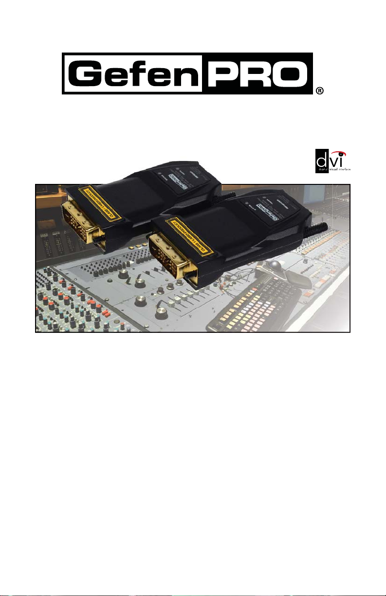
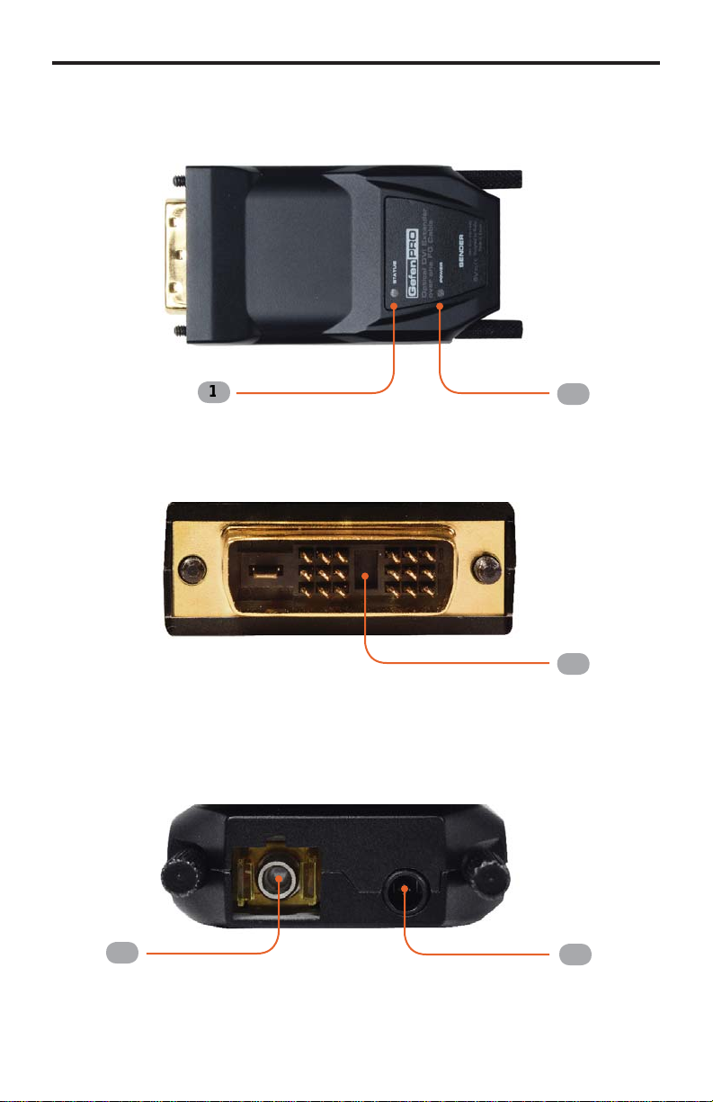
How It Works
C
onnect the
S
ender unit to the DVI source.
C
onnect the Receiver unit to the
DVI displa
y
. Use a sin
g
le strand o
f
SC
-terminated
fi
ber optic cable to connect
the
S
ender unit to the Receiver unit. Use the included 5V D
C
power suppl
y
to
c
onnect the
S
ender unit to an available electrical outlet.

2
OPERATION NOTES
READ THESE NOTES BEFORE INSTALLING OR OPERATIN
G
T
HE DVI FM1500 OPTICAL EXTENDER WITH RECORDABLE EDI
D
• The DVI FM1500
O
ptical Extender with Recordable EDID can use both
s
in
g
le-mode and multi-mode
SC
-terminated optical
fi
ber cables.
• When usin
g
multi-mode
fi
ber optic cables, DVI can be extended t
o
1640
f
eet
(
500 meters
)
.
• The DVI FM1
500
S
ender unit has a de
f
ault built-in EDID o
f
1
9
2
0
x 12
00
.
I
f
the
S
ender unit is pro
g
rammed with another EDID
(
see pa
g
e 9
)
, the
de
f
ault EDID will be erased.
O
nce the de
f
ault EDID is erased, it cannot be
res
t
o
r
ed
.

3
FEATURE
S
Features
• Extends DVI up to 3280
f
eet
(
1000 meters
)
usin
g
sin
g
le-mode
fi
ber optic
cab
l
e
• Extends DVI up to 1640
f
eet
(
500 meters
)
usin
g
multi-mode
fi
ber optic cabl
e
•
S
upports resolutions up to 1920 x 1200
(
WUX
G
A
)
•
O
ptical si
g
nal transmission provides
g
ood immunit
y
to electroma
g
netic
int
e
r
fe
r
e
n
ce
• Virtual EDID pro
g
rammin
g
f
eature provides quick installation and
c
ompatibilit
y
between source and displa
y
•
U
ses sin
g
le-mode or multi-mode
fi
ber optic cabl
e
• Full
y
supports DVI 1.0
S
peci
fi
cations and DD
C
2B via virtual DD
C
•
S
ender module does not require power i
f
the DVI source provides su
ffi
cient
p
ower on pin 14 o
f
the DVI connector
(
most sources do
)
P
acka
g
e Includes
(
1
)
G
e
f
enPro DVI FM1500 -
S
ender uni
t
(
1
)
G
e
f
enPro DVI FM1500 - Receiver uni
t
(
1
)
5V D
C
power suppl
y
(
1
)
Q
uick
S
tart
G
uid
e

4
SENDER UNIT LAYOU
T
Sender uni
t
Fr
o
n
t
T
op
B
ac
k
5
4
3
2
1

5
SENDER UNIT DESCRIPTION
S
1
S
tatu
s
This LED indicator will slowl
y
blink bri
g
ht
g
reen, indicatin
g
that there is a valid
c
onnection between the
S
ender unit and Receiver unit.
2
P
owe
r
This LED indicator will
g
low bri
g
ht
g
reen, when power is applied to the
S
ender
u
nit.
3
DVI Inpu
t
C
onnect this part o
f
the
S
ender unit to the DVI source.
4
S
C Fiber Connecto
r
C
onnect an
SC
-terminated
fi
ber cable
f
rom this
SC
connector to th
e
SC
-connector on the Receiver unit.
5
5V DC Power Supply Connecto
r
C
onnect the optional 5V D
C
power suppl
y
to this receptacle onl
y
i
f
the source
does not suppl
y
enou
g
h volta
g
e to power the
S
ender unit. In most situations,
the power suppl
y
will not be required.

6
RECEIVER UNIT LAYOU
T
Receiver uni
t
Fr
o
n
t
T
op
B
ac
k
5
4
3
2
1

7
RECEIVER UNIT DESCRIPTION
S
1
S
tatu
s
This LED indicator will slowl
y
blink bri
g
ht
g
reen, indicatin
g
that there is a valid
c
onnection between the
S
ender unit and Receiver unit.
2
P
owe
r
This LED indicator will
g
low bri
g
ht
g
reen, when power is applied to the Receiver
u
nit.
3
DVI Outpu
t
C
onnect this part o
f
the Receiver unit to the DVI displa
y
.
4
S
C Fiber Connecto
r
C
onnect an
SC
-terminated
fi
ber cable
f
rom this
SC
connector to th
e
SC
-connector on the
S
ender unit.
5
5V DC Power Supply Connecto
r
C
onnect this cable to the included 5V D
C
power suppl
y
.

How to Connect the DVI FM1500 O
p
tical Extender with Recordable EDI
D
1.
C
onnect the
S
ender unit to the DVI source
.
2.
C
onnect the Receiver unit to the DVI displa
y
.
3
.
C
onnect the
S
ender unit and Receiver unit to
g
ether usin
g
an
SC
-terminated
multi-mode
(
or sin
g
le-mode
)
fi
ber optic cable.
Wirin
g
Dia
g
ram for th
e
D
VI FM1500 O
p
tical Extender with Recordable EDI
D
8
CONNECTING THE DVI FM1500
OPTICAL EXTENDER WITH RECORDABLE EDI
D
GEF-DVI-FM1500
DVI Display
Sender
Receiver
FIBER OPTIC CABLE
DVI Source
®
STOP:
B
e
f
ore continuin
g
, connect the included 5V D
C
power suppl
y
t
o
th
e
R
ece
iv
e
r
u
nit.
I
f
EDID pro
g
rammin
g
is required, then skip to the EDID
Pro
g
rammin
g
Procedure on the next pa
g
e.
IMPORTANT:
I
n m
os
t
cases
the
S
ender module will n
ot
require a
t
power suppl
y
as lon
g
as the DVI source provides su
ffi
cient power
on pin 14 of the DVI connector. If
y
ou are unsure that the source
will suppl
y
enou
g
h power to the
S
ender unit, it is recommended that
the included power supplies be connected to
bo
t
h
the
S
ender and
R
eceiver unit when powerin
g
the DVI FM1500
O
ptical Extender
.

V
irtual EDID Pro
g
rammin
g
Procedur
e
I
f
a
n EDID
is not required
by the DVI source, then EDID programming will not be
d
n
ecessar
y
. EDID pro
g
rammin
g
is
required
if the maximum resolution of the
d
displa
y
does not support 1920 x 1200
(
WUX
G
A
)
.
1. Power on the DVI displa
y
.
2.
C
onnect the 5V D
C
power suppl
y
to the power receptacle o
f
the
S
ender unit.
M
ake sure that the Power LED is
O
N and that the
S
tatus LED is blinkin
g
s
lowl
y
.
3
. Press and hold the EDID PR
G
M button on the
S
ender unit usin
g
a small
p
ointed ob
j
ect. The
S
tatus LED will turn
O
FF.
Sender uni
t
4.
C
onnect the
S
ender unit to the displa
y
(
not to the source
)
.
5
. The
S
tatus LED on the top o
f
the
S
ender unit will be
g
in to blink rapidl
y
,
indicatin
g
that the EDID is bein
g
read
f
rom the displa
y
and stored in the
S
ender unit. A
f
ter about 10 seconds, the
S
tatus LED will blink slowl
y
to
indicate that the EDID pro
g
rammin
g
procedure was success
f
ul.
6
. Disconnect the
S
ender unit
f
rom the displa
y
.
7. Disconnect the power suppl
y
f
rom the
S
ender unit.
8
.
C
onnect the 5V D
C
power suppl
y
to the Receiver unit and connect the
R
eceiver unit to the displa
y
.
9
.
C
onnect the
S
ender unit to the DVI source.
9
E
DID PROGRAMMIN
G
IMPORTANT: The DVI FM1
500
S
ender unit has a de
f
ault built-in
EDID o
f
1920 x 1200. I
f
the
S
ender unit is pro
g
rammed with another
EDID
(
see pa
g
e 9
)
, the de
f
ault EDID will be erased.
O
nce th
e
de
f
ault EDID is erased, it cannot be restored.
Pr
ess
a
n
d
h
o
l
d
th
e
EDID
PR
G
M button.

10
SPECIFICATION
S
M
aximum Pixel
C
lock................................................................................1
65
MH
z
Input Video
S
i
g
nal................................................................................1.2 volts p-
p
Input DD
C
S
i
g
nal...........................................................................5 volts p-p
(
TTL
)
DVI
C
onnector
(S
ender
/
Receiver
)
..........................................DVI-D, 19-pin, mal
e
Fiber
O
ptic
C
onnector
(S
ender
/
Receiver
)
.................................................
SC
t
y
p
e
Power
S
uppl
y
(S
ender
/
Receiver
)
................................................................5V D
C
Power
C
onsumption..........................................................2.5 Watts
(
max.
)
per uni
t
O
peratin
g
Temperature.............................................................................0 ~ 50
°C
Dimensions
(S
ender
/
Receiver
)
..................................1.54” W x 0.57” H x 2.68” D
S
hippin
g
Wei
g
ht..............................................................................................2 lbs.

1
1
WARRANTY
G
e
f
en warrants the equipment it manu
f
actures to be
f
ree
f
rom de
f
ects in material
and workmanship.
I
f
equipment
f
ails because o
f
such de
f
ects and
G
e
f
en is noti
fi
ed within two
(
2
)
y
ears
f
rom the date o
f
shipment,
G
e
f
en will, at its option, repair or replace the
e
quipment, provided that the equipment has not been sub
j
ected to mechanical,
e
lectrical, or other abuse or modi
fi
cations. Equipment that
f
ails under conditions
other than those covered will be repaired at the current price o
f
parts and labor in
eff
ect at the time o
f
repair.
S
uch repairs are warranted
f
or ninet
y
(
90
)
da
y
s
f
rom
the da
y
o
f
reshipment to the Bu
y
er.
This warrant
y
is in lieu o
f
all other warranties expressed or implied, includin
g
without limitation, an
y
implied warrant
y
or merchantabilit
y
or
fi
tness
f
or an
y
p
articular purpose, all o
f
which are expressl
y
disclaimed.
1. Proo
f
o
f
sale ma
y
be required in order to claim warrant
y
.
2.
C
ustomers outside the U
S
are responsible
f
or shippin
g
char
g
es to and
f
rom
G
e
f
en.
3
.
C
opper cables are limited to a 30 da
y
warrant
y
and cables must be in their
ori
g
inal condition.
The in
f
ormation in this manual has been care
f
ull
y
checked and is believed to
be accurate. However,
G
e
f
en assumes no responsibilit
y
f
or an
y
inaccuracies
that ma
y
be contained in this manual. In no event will
G
e
f
en be liable
f
or
direct, indirect, special, incidental, or consequential dama
g
es resultin
g
f
rom
an
y
de
f
ect or omission in this manual, even i
f
advised o
f
the possibilit
y
o
f
such
dama
g
es. The technical in
f
ormation contained herein re
g
ardin
g
the
f
eatures and
s
peci
fi
cations is sub
j
ect to chan
g
e without notice.
For the latest warrant
y
covera
g
e in
f
ormation, re
f
er to the Warrant
y
and Return
Polic
y
under the
S
upport section o
f
the
G
e
f
en Web site at www.
g
e
f
en.com.
P
RODUCT REGISTRATIO
N
P
lease re
g
ister
y
our product online b
y
visitin
g
the Re
g
ister Product pa
g
e
u
nder the Su
pp
ort section of the Gefen Web site
.

R
e
v A
5
20600
Nordho
ff
S
t.
,
C
hatsworth
C
A
9
1
3
1
1
1-
800
-545-
6900
8
1
8
-77
2
-
9
1
00
f
ax:
8
1
8
-77
2
-
9
1
20
www.ge
f
enpro.com support
@
ge
f
enpro.co
m
Pb
This product uses UL listed power supplies.
Table of contents
Other Gefen Pro Extender manuals