Gefen Pro GEF-HDCAT5-ELRPOL2 User manual

1080P
Extender for HDMI ELR
with PoL 2 over CAT5
GEF-HDCAT5-ELRPOL2
User Manual
www.gefenpro.com

ASKING FOR ASSISTANCE
Rev A2
Technical Support:
Telephone (818) 772-9100
(800) 545-6900
Fax (818) 772-9120
Technical Support Hours:
8:00 AM to 5:00 PM Monday thru Friday, Pacific Time
For 24 / 7 support, see the back of the product for the support number
Write To:
Gefen, LLC.
c/o Customer Service
20600 Nordhoff St
Chatsworth, CA 91311
www.gefenpro.com
Notice
Gefen, LLC reserves the right to make changes in the hardware, packaging and
any accompanying documentation without prior written notice.
Extender for HDMI ELR with PoL 2 over CAT5
is a trademark of Gefen, LLC
HDMI, the logo, and High-Definition Multimedia Interface are
trademarks or registered trademarks of HDMI Licensing in the United States and
other countries.
© 2011 Gefen, LLC, All Rights Reserved
All trademarks are the property of their respective owners

CONTENTS
1 Introduction
2 Operation Notes
3 Features
4 Sender Unit Layout
5 Sender Unit Descriptions
6 Receiver Unit Layout
7 Receiver Unit Descriptions
8 Connecting the
Extender for HDMI ELR PoL 2 over CAT5
9 Wiring Diagram
10 DIP Switch Configuration
10 Sender Unit
12 Receiver Unit
15 Network Cable Wiring Diagram
16 Troubleshooting
17 Glossary
24 Specifications
25 Warranty

1
Congratulations on your purchase of the Extender for HDMI ELR PoL2 over CAT5.
Your complete satisfaction is very important to us.
GefenPRO
In the realm of video distribution, certain features are invaluable in a commercial
or broadcast environment. Accommodations such as a build-in power supply
and flat black rack-mount enclosures set GefenPRO apart from our traditional
products. Complex distribution units allow for professional DVI, 3G-SDI, and
HDMI signals to be routed and converted easily and seamlessly, while being
backed up by a renowned and dependable technical support team. Gefen invites
you to explore the GefenPRO product line and hopes that you find the solution
that fits your needs.
The GefenPRO Extender for HDMI ELR with PoL 2 over CAT5
The GefenPRO Extender for HDMI ELR PoL2 over CAT5 does everything that the
GefenPRO Extender for HDMI ELR with PoL 2 over CAT5 does, but adds active
source switching, with an additional Hi-Def input on the Receiver Unit. This pro-
vides the capability to switch between the Hi-Def source connected to the Sender
Unit and a local source connected to the Receiver Unit. The GefenPRO Extender
for HDMI ELR PoL 2 over CAT5 extends a Hi-Def source with multichannel digital
audio at resolutions of up to 1080p Full HD to 330 feet (100 meters), using one
CAT-5 cable. In addition, Gefen’s PoL* technology gives it the capability to power
an additional 5V DC device, up to 2 Amps, at the Receiver unit over the CAT-5
cable.
The Extender for HDMI ELR PoL 2 over CAT5 extends Ethernet and provides an
IR back channel to control A/V sources using the same CAT-5 cable extension.
With the built-in IR Blaster, simply point the IR remote(s) at the display to control
the Hi-Def sources as if they were located in the same room as the display.
How It Works
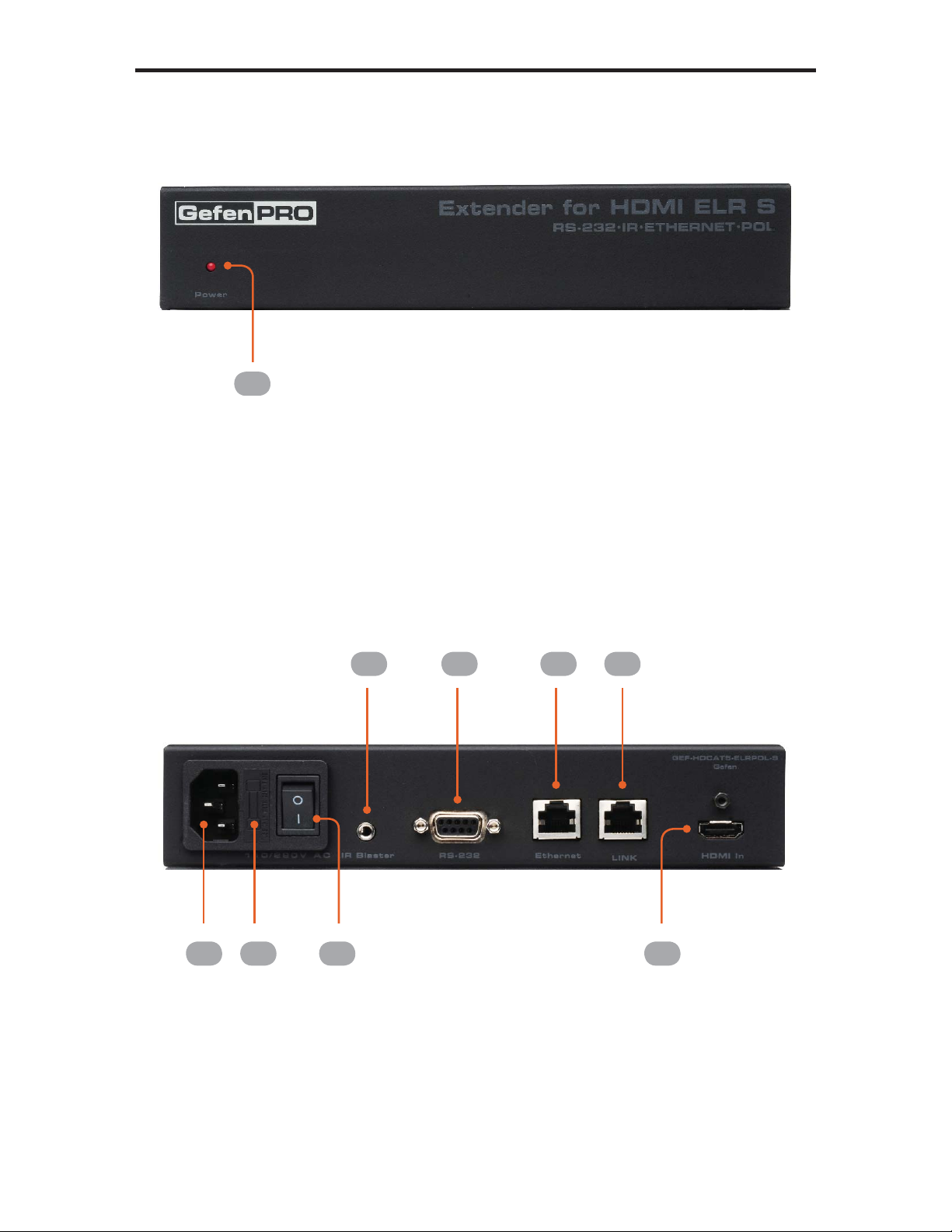
The GefenPRO Extender for HDMI ELR PoL 2 over CAT5 Sender unit is located
next to a set-top box or DVD player source. Use the supplied HMDI cable to con-
nect an HDMI source to the Sender unit. The GefenPRO Extender for HDMI ELR
PoL 2 over CAT5 Receiver unit is located up to 330 feet away, near the display.
Connect the HDTV display and another Hi-Def source to the Receiver Unit.
One CAT-5 cable connects the Sender and Receiver units to each other. The
Ethernet ports on both the Sender and Receiver units are connected to standard
network devices, such as 100Base-T routers and hubs. Multichannel digital audio
is embedded in the HDMI signal (Dolby® TrueHD / DTS-HD Master Audio™).
To use the switching capability, simply power on the Hi-Def source connected to
the Receiver Unit. The Extender will automatically switch to source connected to
the Receiver Unit. To revert to the source connected to the Sender Unit, simply
power down the source connected to the Receiver Unit.
INTRODUCTION

READ THESE NOTES BEFORE INSTALLING OR
OPERATING THE EXTENDER FOR HDMI ELR WITH POL 2 OVER CAT5
• The Extender for HDMI ELR with PoL 2 over CAT5 units are housed in a
metal box for better RF shielding.
• CAT-5 cables should not exceed 330 feet.
• Shielded CAT-6 with metal RJ-45 connectors are recommended to safeguard
against random video flashes caused by electromagnetic interference (EMI).
• The Extender for HDMI ELR with PoL 2 over CAT5 features the ability
to generate compatible EDID and Hot Plug signals for troubleshooting
purposes when dealing with difficult interfacing issues between Source
devices and Displays. Refer to page 13 for details.
• HDCP content is not supported when the unit is in DVI mode. See page 13
for details.
• Ethernet works as a Full Duplex system.
2
OPERATION NOTES

3
HDMI Features
• 225 MHz (up to 12-bit YUV 444 @ 1080p)
• Deep Color
• x.v.Color
• Dolby® TrueHD and DTS-HD Master Audio™
• Lip-Sync
Features
• Extends HDMI at 1080p Full HD and 1920x1200 up to 330 feet
• Extends RS-232 up to 330 feet over a single CAT5
• Supports high bit-rate audio formats (Dolby® TrueHD and DTS-HD Master
Audio™)
• Supports 3DTV
• Locking HDMI input port on Receiver Unit allows the connection of a
secondary Hi-Def source.
• Source-switching between Sender Unit source and Receiver Unit source.
• Fully HDMI and HDCP compliant
• EDID management for rapid integration of source and display devices
• Built-in IR Blaster allows IR remote control of source devices from remote
viewing location
• Internal 110 / 220 V AC Power Supply
• 5V DC, 2 A Locking Power Supply output connector on Receiver unit
• Rack-mountable (with optional Gefen EXT-RACK-1U Rack Shelf)
Package Includes
(1) Extender for HDMI ELR with PoL 2 over CAT5 - Sender Unit
(1) Extender for HDMI ELR with PoL 2 over CAT5 - Receiver Unit
(1) 6 ft. HDMI locking cable (M-M)
(2) AC power cord
(1) User Manual
FEATURES

4
SENDER UNIT LAYOUT
Back
Front
1
2 3
5 6 6 7
84

5
SENDER UNIT DESCRIPTIONS
1 Power
This LED indicator will glow bright red once power has been applied to the unit.
2 110 / 220 V AC
Connect the includedAC power cord to this power receptacle.
3 Fuse Drawer
Each power receptacle houses a fuse drawer. Within each fuse drawer are two
(2) 250 V fuses. One fuse is active and the other is a spare.
4 Power Switch
Turn the power ON or OFF using this switch.
5 IR Blaster
Connect an IR Blaster cable (Gefen part no. EXT-2IREMIT) from this port to the
Hi-Def source to control the source from the viewing location.
6 RS-232
This RS-232 serial port is used to update the Receiver Unit firmware.
7 Ethernet
Connects the Sender Unit to the network using Ethernet cabling.
8 Link
Connects the Sender Unit to the Receiver Unit using CAT-5 cabling.
9 HDMI In
Connect a Hi-Def source to this locking HDMI port, using the included HDMI
cable.

6
RECEIVER UNIT LAYOUT
Back
Front
1 2 3 4
5
6 7 8 9
10 11

7
RECEIVER UNIT DESCRIPTIONS
1 Local
This LED indicator will glow bright green when the Receiver Unit is switched to
use the Local HDMI input.
2 Select
Switches between the HDMI input on the Sender Unit and the Local HDMI In
port on the Receiver Unit.
3 IR
This IR window receives signals from the Hi-Def source IR remote control. The
IR signals are sent back to the source device, when using an IR Blaster on the
Sender.
4 Power
This LED indicator will glow bright red once power has been applied to the unit.
5 5V DC Out
Connect an optional locking (Gefen part no. CAB-PWR-06LL) or non-locking
(Gefen Part no. CAB-PWR-06NL) power cord to this the included 5 V DC
locking power supply connector to power additional devices.
6 Ext IR
Connect an IR Extender (Gefen part no. EXT-RMT-EXTIR) cable from this port
to the Hi-Def source to extend the IR control.
7 RS-232
This RS-232 serial port is used to update the Receiver Unit firmware.
8 Ethernet
Connects the Receiver Unit to the network device.
9 Link
Connects the Receiver Unit to the Sender Unit using CAT-5 cabling.
10 HDMI Out
Connect an HDTV display or other output device to this locking HDMI port.
11 Local HDMI In
Connect a secondary Hi-Def source device to this locking HDMI port.

8
CONNECTING THE EXTENDER
FOR HDMI ELR WITH POL 2 OVER CAT5
1. Connect the Hi-Def source to the Sender Unit using the included HDMI cable.
2. Optionally connect a secondary Hi-Def source to the Receiver Unit.
Connecting a secondary Hi-Def source to the Receiver Unit provides the ability
to switch between the a Hi-Def source connected to the Sender Unit and the Hi-
Def source connected to the Receiver Unit. In this way, the Extender for HDMI
ELR with PoL 2 over CAT5 functions as both a 2x1 switcher and an extender.
3. Use an HDMI cable to connect the HDTV display to the Receiver Unit.
4. Connect the Ethernet device/router to the Ethernet input port on the Sender
unit using a CAT-5, CAT-5e or CAT-6 cable. Connect the Ethernet output port
on the Receiver Unit to the remote device/router with a CAT-5, CAT-5e or
CAT-6 cable.
5. Use a CAT-5 or CAT-6 cable up to 330 ft (100 meters) to connect the Link
ports on both the Sender Unit and Receiver Unit.
If terminating network cables in the field, please adhere to the
TIA/EIA568B specification. See page 15 for details.
6. Connect the includedAC power cord to the Sender Unit Plug the power cord
into an available electrical outlet.
Connect an optional power cable (CAB-PWR-06LL or
CAB-PWR-06NL) to the Receiver Unit. The Receiver Unit supplies
5 V DC (@ 2A) to power an additional device.
7. Power on the HDTV display and the Hi-Def source(s) connected to the Sender
Unit and the Receiver Unit.

9
Wiring Diagram for the Extender for HDMI ELR with PoL 2 over CAT5
CONNECTING THE EXTENDER
FOR HDMI ELR WITH POL 2 OVER CAT5
GEF-HDCAT5-ELRPOL2
CAT5 LINK CABLE
(Up to 330 ft)
ETHERNET CABLE
HDMI CABLE
Sender
100BASE-T Router
100BASE-T Router
Set-top Box
HDMI Display
Local HDMI Input
Sd
Attention: This product should always be connected to a grounded
electrical socket.

10
DIP SWITCH CONFIGURATION
Sender Unit
The GefenPRO Extender for HDMI ELR with PoL 2 over CAT5 contains DIP
switches on the bottom of the Sender Unit. Each DIP switch performs a different
function.
•
•
•
•
•
DIP Switch 1 - Green Mode (Default = ON)
• OFF - Enable Green Mode
When DIP switch 1 on the Sender Unt is set to the OFF position, the Sender
Unit is placed in Green Mode. In this mode, the unit is not powered unless
+5V is detected on pin 18 of the HDMI cable. Green Mode consumes less
than 1 Watt of power.
• ON - Disable Green Mode
If DIP switch 1 is set to the ON position, then the Sender Unit is always
powered.
Two DIP switches located on
the bottom of the Sender Unit.
•
•
•
•
•
•
•
•
•
•
•
•
•
•
•
•
•
•
•
•
•
•
•
•
•
•
•
•
•
•
•
•
••
•
•
•
•
•
•
•
•
•
•
•
•
•
•
•
•
•
•
•
•
•
•
•
•
•
•
•
•
•
•
•
•
•
•
•
•
•
•
•
•
•
•
•
•
•
•
•
•
•
•
•
•
•
•
•
•
•
•
•
•
•
•
•
•
•
•
•
•
•
•
•
•
•
•
•
•
•
•
••
Both the Sender Unit and Receiver Unit must be placed in Green
Mode in order to use the Green Mode feature.

11
DIP SWITCH CONFIGURATION
Sender Unit
DIP Switch 2 - External Boot Loader Enable (Default = OFF)
• OFF - Disable
Setting DIP switch 1 to the OFF position disables the boot loader function.
• ON - Enable
Set DIP switch 1 to the ON position when using the bootloader to update the
firmware on the Sender Unit. In this mode, the Sender Unit will not function
as an Extender.

12
DIP SWITCH CONFIGURATION
Receiver Unit
The GefenPRO Extender for HDMI ELR with PoL 2 over CAT5 contains DIP
switches on the bottom of the Receiver Unit. Each of these DIP switch performs
a different function.
See the next page for a description of the DIP switches.
Six DIP switches located on
the bottom of the Receiver
Unit.

13
DIP SWITCH CONFIGURATION
Receiver Unit
DIP Switch 1 - EDID Mode (Default = OFF)
• ON - Pass-Through Mode
DDC and HPD are passed through. Both the connection status and the full
video capabilities of the monitor are used by the source device.
• OFF - Local EDID Mode
Local EDID is used instead of the EDID from the display device. EDID
features newer than HDMI 1.3 are removed when the display is read. This
provides a general EDID which is compatible with more displays.
DIP Switch 2 - Hot Plug Detect (Default = OFF)*
• ON - HPD Pass-Through
HPD follows upstream HPD towards the source. The HPD signal will reflect
the connection status between the display device and the source device. If
the source or monitor is temporarily disconnected then reconnected, there
will be a delay of 20 - 30 seconds before the content is restored to the
monitor.
• OFF - HPD Always High
The HPD signal remains high regardless of the downstream HPD state.
If the source or monitor does not properly handle HPD (no picture after
connecting / reconnecting source or display), set this DIP switch to the OFF
position.
DIP Switch 3 - Supports DVI Connections (Default = ON)*
• ON - Disable HDCP
If a DVI connection is used, set DIP 3 to the ON position. DVI is supported
by disabling HDCP pass-through.
• OFF - Enable HDCP
If an HDMI device is connected, set DIP 3 in the OFF position.
*DIP switch is only operational when using Local EDID (DIP 1 = OFF).

14
DIP SWITCH CONFIGURATION
Receiver Unit
DIP Switch 4 - Green Mode (Default = OFF)
• OFF - Enable Green Mode
When DIP switch 1 on the Receiver Unit is set to the OFF position, the
Receiver Unit is placed in Green Mode. In this mode, the unit is not powered
unless +5V is detected on pin 18 of the HDMI cable. Green Mode consumes
less than 1 Watt of power.
• ON - Disable Green Mode
If DIP switch 1 is set to the ON position, then the Sender Unit is always
powered.
DIP Switch 5 - External Boot Loader Enable (Default = OFF)
• OFF - Disable
Setting DIP switch 1 to the OFF position disables the boot loader function.
• ON - Enable
Set DIP switch 1 to the ON position when using the bootloader to update
the firmware on the Receiver Unit. In this mode, the Receiver Unit will not
function as an Extender.
DIP Switch 6 - Not Used
• Reserved for future expansion.
Both the Sender Unit and Receiver Unit must be placed in Green
Mode in order to use the Green Mode feature.

15
NETWORK CABLE WIRING DIAGRAM
12345678
Gefen recommends the TIA/EIA-568-B wiring option. Please adhere to the table
below when field terminating cable for use with Gefen products.
Pin Color
1 Orange / White
2 Orange
3 Green / White
4 Blue
5 Blue / White
6 Green
7 Brown / White
8 Brown
CAT-5, CAT-5e, and CAT-6 cabling comes in stranded and solid core types.
Gefen recommends using solid core cabling. CAT-6 cable is also recommended.
It is recommended to use one continuous run from one end to the other. In some
cases, connecting through a patch might not work.

16
TROUBLESHOOTING
Cable recommendations
Solid core CAT-5e cable rated at 350 MHz and terminated in 568a or 568b is the
minimum requirement. For resolutions greater than 1280x1024 or 1080i, Gefen
recommends solid shielded CAT-6 cables.
No video
Make sure that DIP switch 2 on the Sender Unit is set to the OFF position. Also
make sure that DIP switch 5 on the Receiver Unit is set to the OFF position. If
either of these DIP switches are in the ON position (External Boot Loader Enable,
see page 10 and 14) then the Sender Unit or Receiver Unit will not function as an
extender. Next, make sure that the CAT-5 cable, connecting the Sender Unit and
Receiver Unit is connected to the LINK port. If this does not solve the issue, try
disconnecting and then reconnecting the AC power cord from the Sender Unit.
Also, verify that both units are working with short CAT-5e cables (15 - 20 feet).
Intermittent loss of video
Flickering or a blinking image is the result of a loss of sync between the display
and the source. Try lowering the source resolution (e.g. from 1080p to 720p). If
this solves the issue, then the CAT-5 cables being used to connect the Sender
Unit and the Receiver Unit are unable to handle the bandwidth of the higher
resolution and thus you are losing sync. Replace the existing CAT-5 cables with
a shielded CAT-6 cable. Electromagnetic Interference (EMI) from fluorescent
lights, generators, and A/C unit motors can also cause intermittent loss of video.
Shielded CAT-6 cable with the drain wire soldered to the connectors will resolve
the issue. Also make sure to eliminate any patch panels and wall plates. Patch
panels and wall plates are prone to EMI if they are not shielded properly.
Image is tinted green or pink
An image that is tinted green or pink is the result of the incorrect color space
being transmitted. Make sure that the display and source both support the same
color space. Setting DIP switch 1 on the Receiver Unit, to the OFF position, will
use the Local EDID. EDID features newer than HDMI 1.3 are removed when
the display is read. This provides a general EDID which is compatible with more
displays.

17
GLOSSARY
ADC
Apple Display Connector. TheADC interface is a proprietary interface developed
by Apple that combines analog and digital signals, USB, and power in a single
cable.
CAT-5
Category-5 cable, commonly known as Cat-5, is an unshielded twisted pair type
cable designed for high signal integrity. The actual standard defines specific
electrical properties of the wire, but it is most commonly known as being rated
for its Ethernet capability of 100 Mbit/s. Its specific standard designation is EIA/
TIA-568. Cat 5 cable typically has three twists per inch of each twisted pair of 24
gauge copper wires within the cable.
CAT-5e
Similar to Cat 5 cable, but is enhanced to support speeds of up to 1000 megabits
per second.
CRT
An acronym for Cathode Ray Tube: a common type of computer display
hardware.
DDC
Short form for Display Data Channel. It is a VESA standard for communication
between a monitor and a video adapter. Using DDC, a monitor can inform the
video card about its properties, such as maximum resolution and color depth.
The video card can then use this information to ensure that the user is presented
with valid options for configuring the display.
A
C
D
Other manuals for GEF-HDCAT5-ELRPOL2
2
Table of contents
Other Gefen Pro Extender manuals
Popular Extender manuals by other brands

LIBERTY AV SOLUTIONS
LIBERTY AV SOLUTIONS DL-1H1V-WPKT-H2 quick guide

Encore
Encore N300 Series Quick installation guide

Intercoax
Intercoax EUP-2601T quick start guide

Intelix
Intelix DIGI-BSR-4K installation guide

Extron electronics
Extron electronics FOX 500 DVI Specification sheet

TP-Link
TP-Link TL-WPA8631P Quick installation guide