1
Congratulations on your purchase of the Extender for HDMI ELR with PoL over
CAT5. Your complete satisfaction is very important to us.
GefenPRO
In the realm of video distribution, certain features are invaluable in a commercial
or broadcast environment. Accommodations such as a build-in power supply and
flat black rack-mount enclosures set GefenPRO apart from our traditional prod-
ucts. Complex distribution units allow for professional DVI, 3G-SDI, and HDMI
signals to be routed and converted easily and seamlessly, while being backed
up by a renowned and dependable technical support team. Gefen invites you to
explore the GefenPRO product line and hopes that you find the solution that fits
your needs.
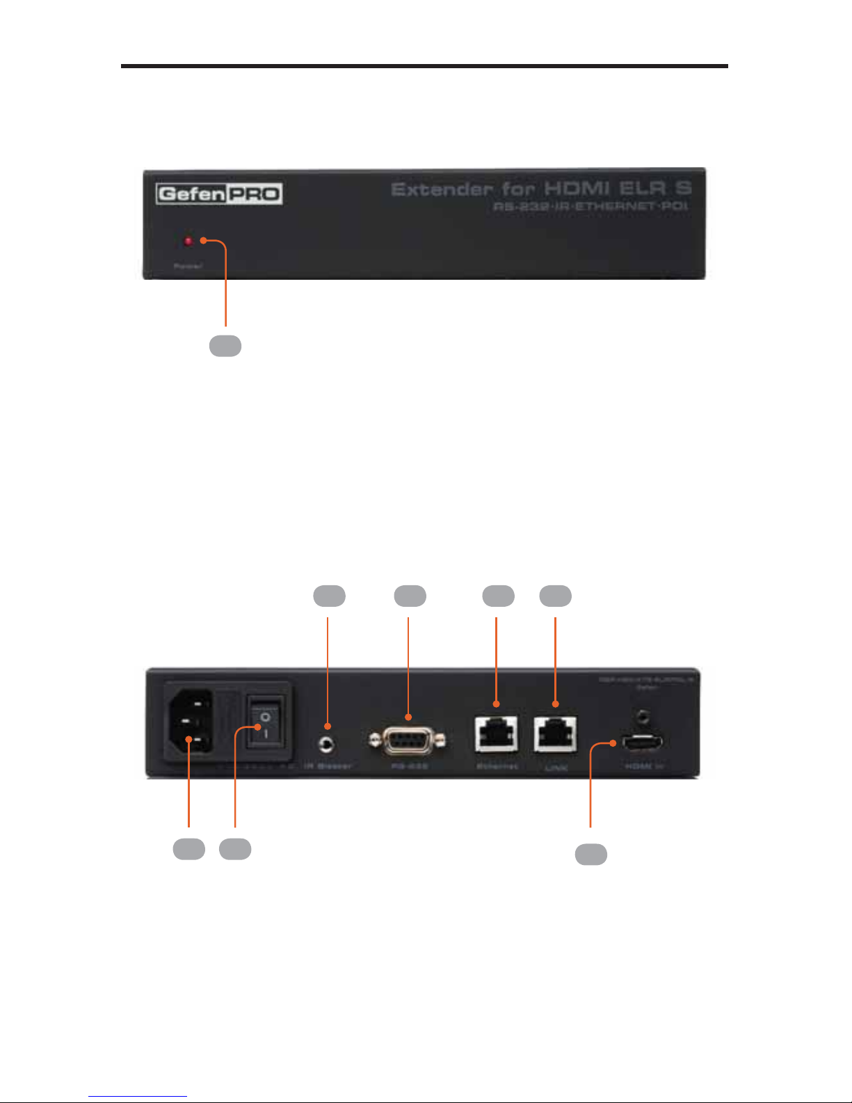
The GefenPRO Extender for HDMI ELR with PoL over CAT5
The GefenPRO Extender for HDMI ELR with PoL (Power over Link) over CAT5
extends a Hi-Def source with multichannel digital audio at resolutions of up to
1080p Full HD to 330 feet (100 meters) using one CAT-5 cable. Also, it has the
capability to power a separate 5V DC device from the Receiver unit, sharing the
5V DC power, transmitted over the CAT-5 cable, up to 2 Amps at the Receiver
Unit. DVI-D is supported when used with an HDMI to DVI Adapter, providing
greater flexibility and options when integrating several home theater components.
This product also extends Ethernet and provides an IR back channel to control
AV sources using the same CAT-5 cable extension. 3D content is supported
when a 3DTV and a 3D source are connected to the Sender Unit. With the built-
in IR Blaster, simply point the IR remote(s) at the display to control the Hi-Def
sources as if they were located in the same room as the display.
How It Works
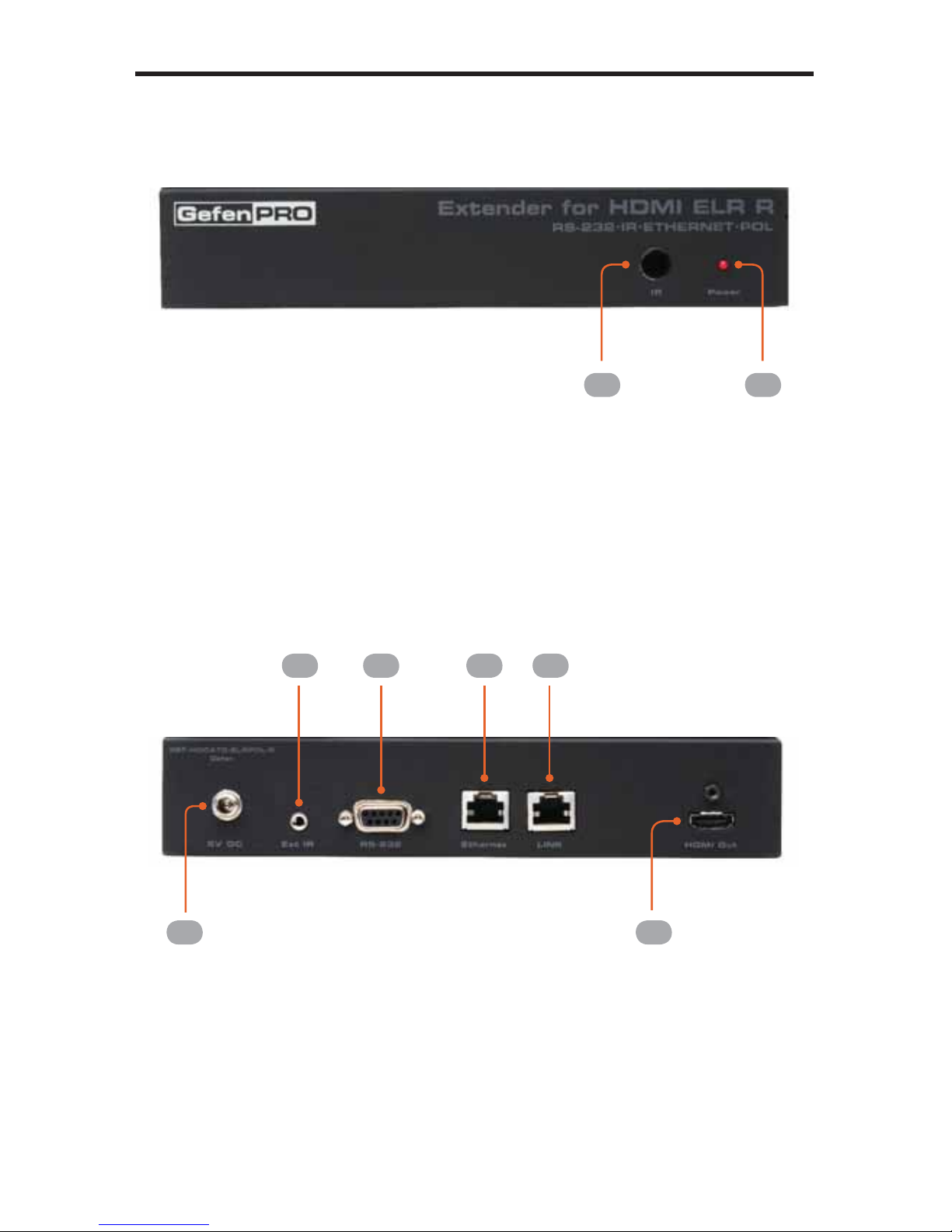
The GefenPRO Extender for HDMI ELR with PoL over CAT5 Sender unit is
located next to a set-top box or DVD player source. Connect an HDMI source
with the supplied cables to the GefenPRO Extender for HDMI ELR with PoL over
CAT5 to the Sender Unit. The GefenPRO Extender for HDMI ELR with PoL over
CAT5 Receiver unit is located next to the display - up to 330 feet away from the
source. The HDTV display plugs into the back of the GefenPRO Extender for
HDMI ELR with PoL over CAT5 Receiver unit. One CAT-5 cable connects the
Sender and the Receiver units to each other. The Ethernet ports on both the
Sender and Receiver units are connected to standard network devices such as
Ethernet switches. Multichannel digital audio is embedded in the HDMI signal
(Dolby TrueHD / DTS-HD Master Audio).
INTRODUCTION