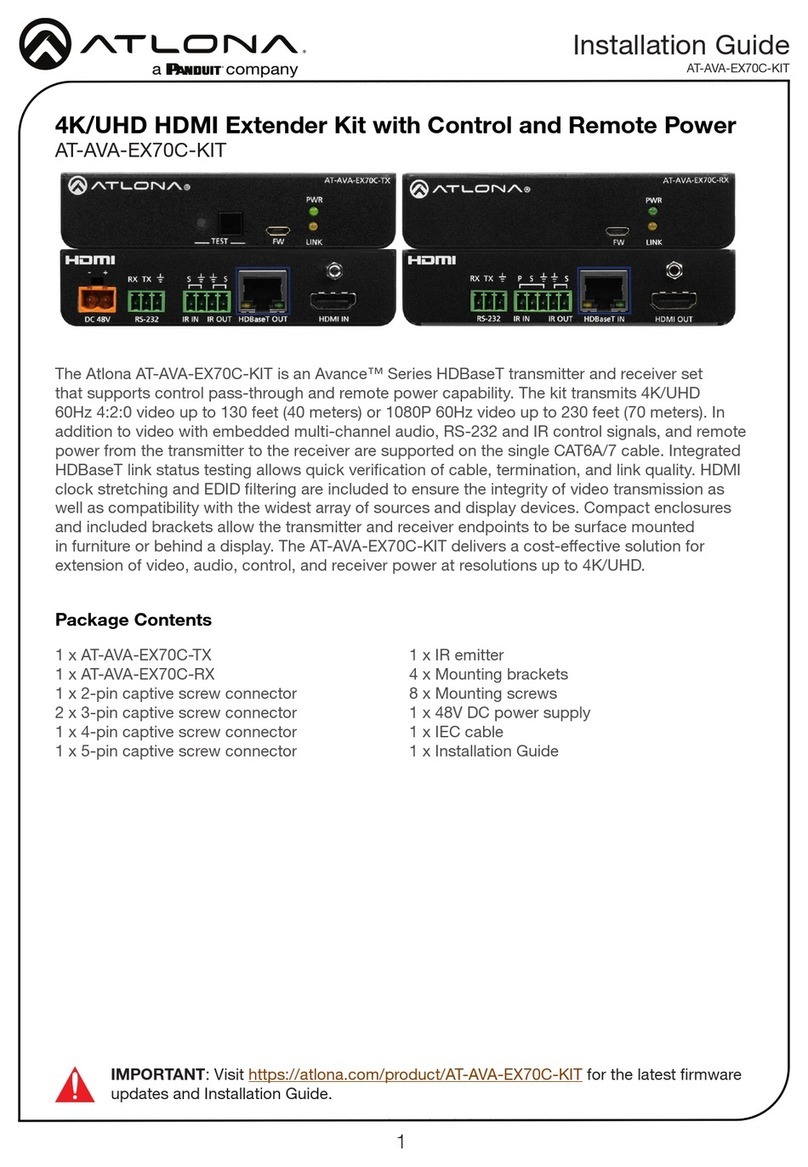
Panduit Atlona AT-HDVS-150-KIT User manual
Other Panduit Extender manuals
Panduit
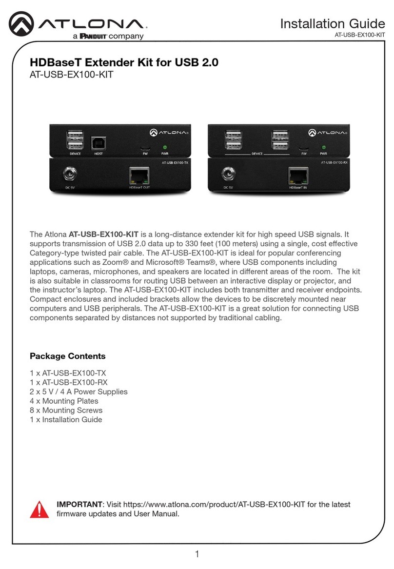
Panduit ATLONA AT-USB-EX100-KIT User manual

Panduit
Panduit Atlona Avance AT-AVA-EX70-KIT User manual

Panduit
Panduit ATLONA AT-USB-EX100-KIT User manual
Panduit
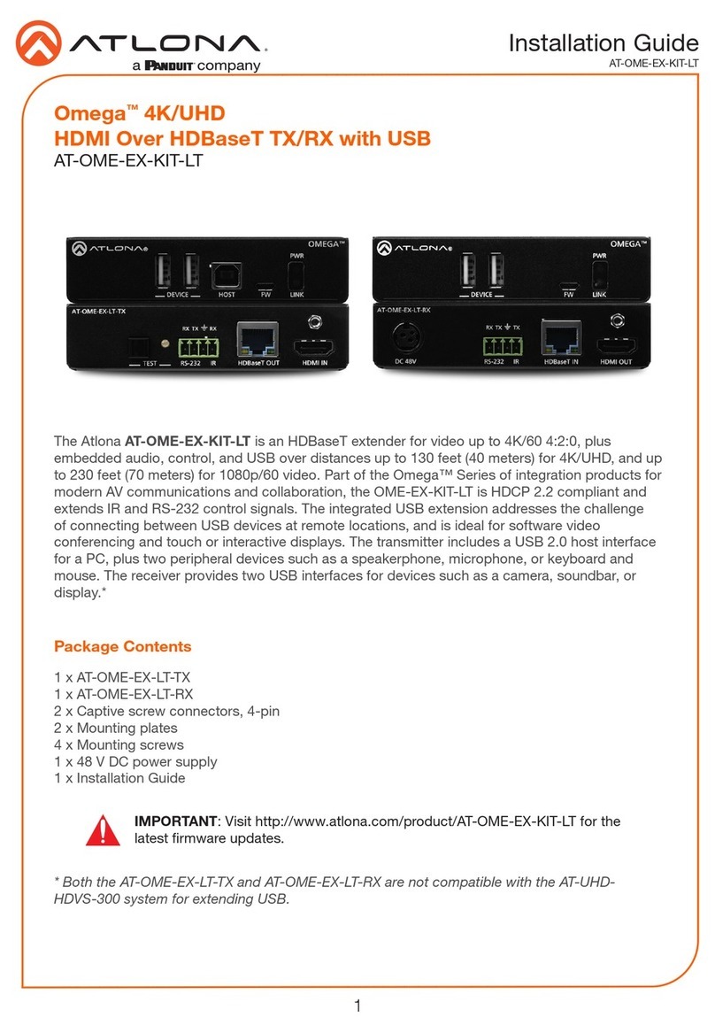
Panduit Atlona Omega AT-OME-EX-KIT-LT Series User manual
Panduit
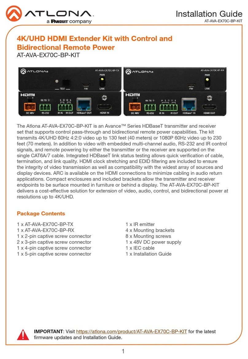
Panduit ATLONA AT-AVA-EX70C-BP-KIT User manual
Panduit
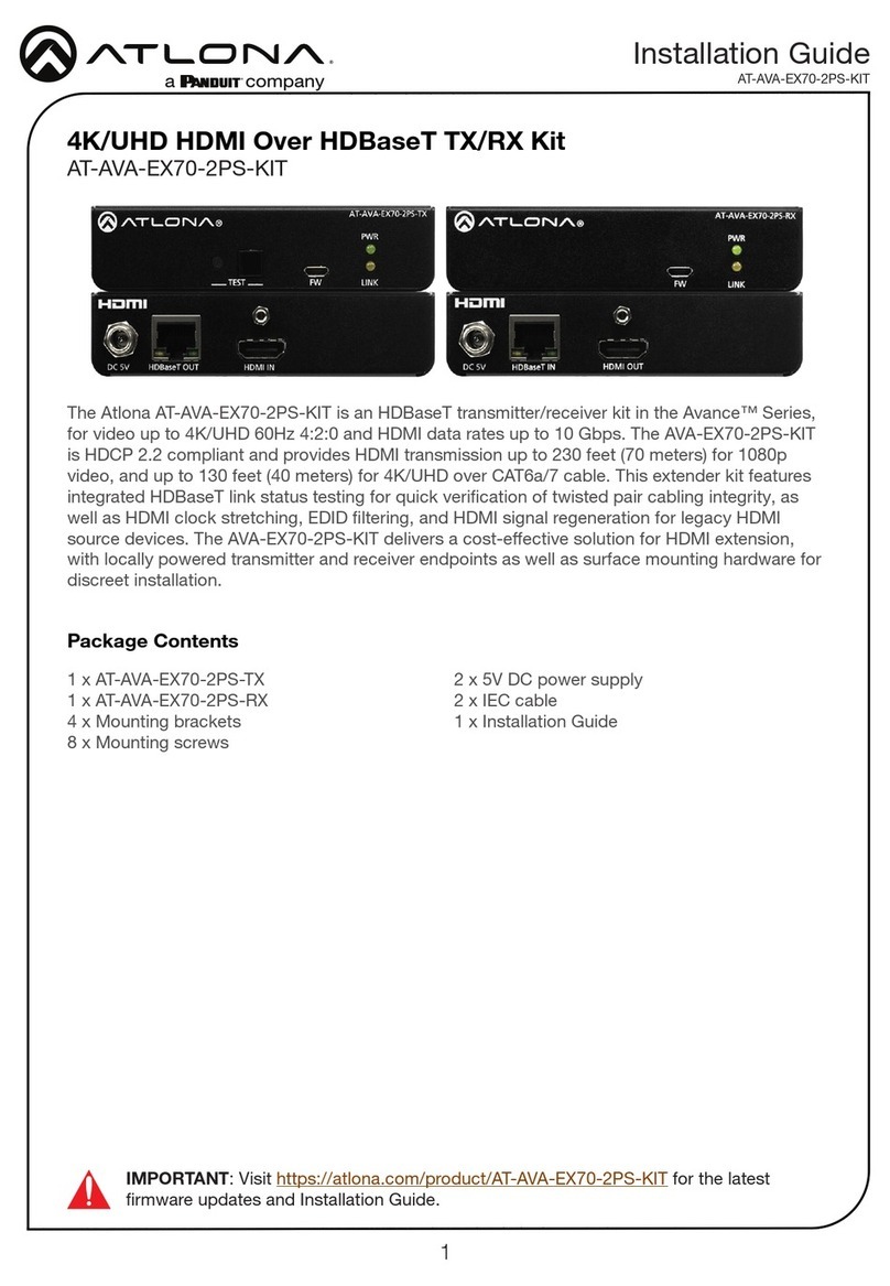
Panduit ATLONA AT-AVA-EX70-2PS-KIT User manual

Panduit
Panduit Atlona Avance AT-AVA-EX70-KIT User manual
Panduit
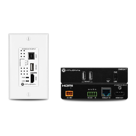
Panduit Atlona Omega AT-OME-EX-WP-KIT-LT User manual

Panduit
Panduit ATLONA AT-AVA-EX100CE-BP-KIT User manual

Panduit
Panduit Atlona Omega AT-OME-EX-TX-WP-E Series User manual
Popular Extender manuals by other brands

foxunhd
foxunhd SX-AEX01 operating instructions

TERK Technologies
TERK Technologies LFIRX2 owner's manual

Devolo
Devolo Audio Extender supplementary guide

Edimax
Edimax EW-7438RPn V2 instructions

Shinybow USA
Shinybow USA SB-6335T5 instruction manual

SECO-LARM
SECO-LARM ENFORCER EVT-PB1-V1TGQ installation manual
