gefran ILI Series User manual

PRESSURE SENSORS FOR HIGH
TEMPERATURE IO-Link IMPACT
Cod. 80618 edit. 12/2019 - ENG

280618_MAN_IO-LINK IMPACT_12-2019_ENG
INDEX
1. GENERAL INFORMATION...............................................................................................................................................................4
1.1. General information .................................................................................................................................................................4
1.2. Copyright..................................................................................................................................................................................4
1.3. Correct use ..............................................................................................................................................................................4
2. MELT IO-LINK...................................................................................................................................................................................4
2.1. Impact IO-Link models.............................................................................................................................................................4
2.2. Transducer General Information .............................................................................................................................................4
2.3. Models .....................................................................................................................................................................................5
3. TECHNICAL DATA ...........................................................................................................................................................................6
4. MECHANICAL DIMENSIONS...........................................................................................................................................................7
5. INSTALLATION AND POSITIONING ON THE MACHINE ...............................................................................................................7
5.1. Installation seat........................................................................................................................................................................7
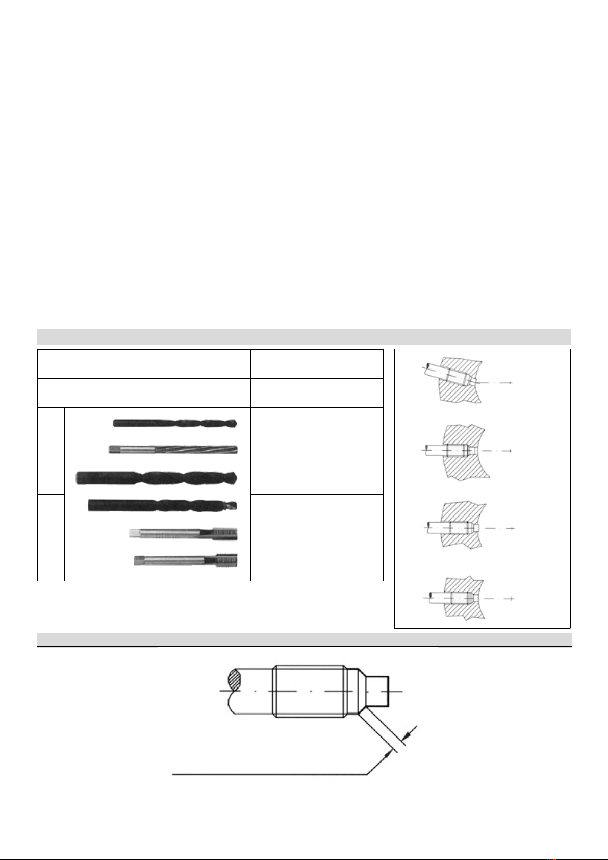
5.2. Drilling tool kit...........................................................................................................................................................................8
5.3. Torquing the sensor ...............................................................................................................................................................10
5.4. Connecting amplier ..............................................................................................................................................................10
6. INSTALLATION AND ELECTRICAL CONNECTIONS................................................................................................................... 11
6.1. General precautions............................................................................................................................................................... 11
6.2. Electrical installation .............................................................................................................................................................. 11
6.3. Standard reference ................................................................................................................................................................13
6.4. EMC and RoHS Requisites....................................................................................................................................................13
7. COMMAND MODES ......................................................................................................................................................................14
7.1. IO-Link Information ...............................................................................................................................................................14
7.2. SIO mode and IO-Link mode .................................................................................................................................................14
7.3. Process Data mapping (IO-Link)............................................................................................................................................14
7.4. Parameterization data............................................................................................................................................................15
7.5. LED behavior .........................................................................................................................................................................21
7.6. Switching signal channels (SSCs) conguration....................................................................................................................22
7.7. Reranging (LRV/URV) – only for SIL 2 / PL d analog output version –..................................................................................24
7.8. Relay Threshold change – only for SIL 2 / PL d relay output version – .................................................................................25
7.9. Damping lter parameter .......................................................................................................................................................25
7.10. Autozero command..............................................................................................................................................................25
7.11. Enable CAL parameter.........................................................................................................................................................26
7.12. Analog Out Type parameter .................................................................................................................................................26
7.13. Autocompensation effect on Impact series ..........................................................................................................................26
8. MAINTENANCE..............................................................................................................................................................................27
8.1. Maintenance ..........................................................................................................................................................................27
8.2. Transport, storage and disposal
9. FUNCTIONAL SAFETY NOTES (FOR SIL 2 / PL d CERTIFIED VERSIONS ONLY) -waiting for Notied Body certication-............28
9.1. Application..............................................................................................................................................................................28
9.2. Restrictions of use .................................................................................................................................................................30
9.3. Maintenance and periodic checks..........................................................................................................................................30
9.4. Mean Time to Restoration .....................................................................................................................................................31
9.5. Indication on response times .................................................................................................................................................31
9.6. Effects on the safety function of deviations in performance...................................................................................................31
9.7. Inhibition and suspension of the safety function ....................................................................................................................31
9.8. Indications and alarms...........................................................................................................................................................32

3
80618_MAN_IO-LINK IMPACT_12-2019_ENG
10. RELAY APPLICATION NOTES ....................................................................................................................................................33
11. RESOLUTION PROBLEMS .........................................................................................................................................................37
12. APPENDIX B: IP PROTECTION...................................................................................................................................................38
13. APPENDIX C: ACCURACY CLASS.............................................................................................................................................39
13.1. Calibration Curve .................................................................................................................................................................39
13.2. Repeatability ........................................................................................................................................................................39
13.3. Hysteresis ............................................................................................................................................................................40
13.4. Linearity ...............................................................................................................................................................................40
14. APPENDIX D: REGISTRATION MAINTENANCE........................................................................................................................41

480618_MAN_IO-LINK IMPACT_12-2019_ENG
1. GENERAL INFORMATION
1.1. General information
This manual refers to the following products:
ILI and must be kept near the equipment for easy reading and consultation.
It must be read, understood, and strictly follow in order to avoid and prevent accidents and/or malfunctions.
Gefran will not be liable for any injury to people and/or damage to property deriving from disregard of this manual.
1.2. Copyright
Any reproduction of this document, even partial or for internal use, requires Gefran’s approval.
1.3. Correct use
Gefran Melt pressure sensors are designed and built to measure the pressure and temperature variable of melted plastic at different
temperatures according to the lling uid used.
The correct temperature range is:
• Up to 350°C
If the sensors are used as a safety component in accordante with the Machinery Directive, the equipment builder must take all
necessary precautions to ensure that any malfunctions of the Melt pressure sensor do not injury to people and/or damage to property.
Installation and maintenance must only be carried out by suitably skilled and qualied personnel.
2. MELT IO-LINK
2.1. IMPACT IO-LINK MODELS
IMPACT “ILI” series of Gefran, are pressure transmitters, without transmission uid, for using in High temperature process environment
(up to 350°C). Pressure is transduced by a micro-worked silicon structure (MEMS) and the operating principle is “piezoresistive”.
“IMPACT” is Gefran’s exclusive series of high-temperature pressure sensors that use the piezoresistive principle.
This new series “ILI” with “IO-Link” digital output is a Smart device specically designed to meet the requirements of “Industry 4.0”
environment, with auxiliary information suitable to prevent machine downtime.
The main characteristic of “IMPACT” sensors is that they do not contain any transmission uid.
The sensitive element, directly positioned behind the contact membrane, is realised in silicon through microprocessing techniques.
The micro structure includes the measurement membrane and piezoresistors.
The minimum deection required by the sensitive element makes it possible to use very robust mechanics.
The process contact membrane can be up to 15 times thicker than the membrane used in traditional Melt sensors.
Supplied in 2 different congurations, rigid stem, and rigid + exible and 4 mechanics, single and modular xed and single and
modular oating, the Melt sensors of GEFRAN are able to meet all installation requirements in the eld.
The coverage relative to the pressures that can be detected by the sensor is almost total; we start from the probe with a minimum
range of 0-10 bar to arrive at a version with a scale of 0-1000bar. All models in the catalogue can be supplied in two different accuracy
classes; in particular class M, with accuracy 0.5%FS and class H, with 0.25%FS accuracy.
Thanks to PLd and SIL2 approvals, this product is suitable for Functional Safety applications.
2.2. Transducer General Information
IO-Link transducer offers different options related to process data conguration and functional features (see datasheet for selection
of ordering codes):
• Standard transducer with only IO-Link pressure data available
• T integrated transducer with IO-Link pressure + tip temperature measurement data available
• SIL 2 / PL d certied transducer with IO-Link output + Analog output (Voltage or Current output), available in standard and T
integrated version
• SIL 2 / PL d certied transducer with IO-Link output + Relay output, available in standard and T integrated version

5
80618_MAN_IO-LINK IMPACT_12-2019_ENG
2.3. Models
DIGITAL OUTPUT
ILI0 ILI1

680618_MAN_IO-LINK IMPACT_12-2019_ENG
3. TECHNICAL DATA
MELT IMPACT PRESSURE TRANSDUCERS
ILI series
Table 1
Accuracy (1) H <±0.25%FS (100...1000 bar)
M <±0.5%FS (10...1000 bar)
Thermal drift in compesated range:
Zero / Calibration / Sensibility < 0.02% FS/°C
Measuring ranges 0…10 to 0…1200 bar
0…150 to 0...15000 psi
Maximum overpressure (without degrading performances) 1.5 x FS (up to 1200 bar/ 17400 psi max)
Measurement principle Piezoresistive
Power supply 18...30 Vdc
Maximum current absorption 1W (1,2W with optional relay)
Zero offset < ± 0.25% FS
Zero adjustment “Autozero” function
Communication interface IO-Link
Min Cycle time 2,7 ms (2 bytes PDI)
3,5 ms (4 bytes PDI)
IO-Link version 1.1
Transmission type COM2 (38.4 kB)
Prole Smart Sensor Generic Prole
SIO mode Yes
Required class for Master port A
Pressure process data resolution 14 bit
Temperature process data resolution 16 bit
Analog output resolution 16 bit
Rangeability 3:1 (Analog output option)
Calibration signal 80% FS
Reverse polarity protection on power supply YES
Compensated temperature range (housing) 0...+85°C
Operating temperature range (housing) -30...+85°C
Storage temperature range (housing) -40...+125°C
Diaphragm maximum temperature 23…350 °C / 660 °F
Zero drift on process temp. 20 to 350°C < ± 1.2%FS
Span drift on process temp. 20 to 350°C < ± 1%FS
Integral temperature (optional) Accuracy ± 2 °C
Standard material in contact with process medium
Diaphragm:
• 15-5PH with GTP+ coating
Stem:
• 17-4 PH
Protection degree (5 pole female connector) IP65 with suitable mating connector
Insulation resistance (at 50Vdc) >1000 Mohm
Electromagnetic compatibility – Emission
EN 61326-1
EN 61326-2-3
EN61326-3-1
Electromagnetic compatibility – Immunity
EN 61326-1
EN 61326-2-3
EN61326-3-1
FS = Full scale output :
(1) BFSL method (Best Fit Straight Line): includes combined effects of Non-Linearity, Hysteresis and Repeatability (according to IEC 62828-2).
Sensors are manufactured in compliance with:
- EMC compatibility directive
- RoHS directive
- Machinery directive
Electrical installation requirements and Conformity certicate are available on our web site: www.gefran.com

7
80618_MAN_IO-LINK IMPACT_12-2019_ENG
4. MECHANICAL DIMENSIONS
For the mechanical dimensions keep as reference the product datasheets or Gefran website www.gefran.com
5. INSTALLATION AND POSITIONING ON THE MACHINE
TECHNICAL DATA
Extrusion processes require very high temperatures. Extrusion pressure can be checked by means of especially designed transducers.
The IMPACT series sensors are suitable for pressure measurements with high temperature and are based on the piezoresistive
technology.
Following advice for extending the sensors lifetime:
a) Avoid shocks and abrasions to the in contact diaphragm. Protect the transducer with its cover each time you remove it from its seat.
b) The seat must be prepared perfectly and with appropriate tools in order to respect the depth and axiality of the holes and tapping.
Pay particular attention to the coaxiality of the holes to the thread, because diaxialities greater than 0.2 mm will break the transducer during
assembly. It is essential that hole depth guarantee the absence of chambers or air pockets in which extrusion material may be trapped.
To prevent contact with the extrusion screw or with tools used to clean the extrusion chamber, the front diaphragm must not extend
from the inner wall of the extruder.
c) Before assembling the transducer in machines already in operation, make sure that the housing is clean.
Remove any residual with the suitable cleaning device.
d) The transducer should be removed only with the machine empty (without pressure) but still hot.
e) The transducer should be cleaned with solvents for the material being processed.
Any mechanical action on the contact diaphragm modifies its operation and could break it.
5.1. Installation seat
The installation seat has to be realized:
Incorrect working or shape of the side can result in properties out of specification, bad behaviour or damage to the sensor.
The side should be clean and without any polymer residual.
D1 1/2-20UNF M18x1.5
D2 .313 ±.001”
[7.95 ±0.02mm]
.398 ±.001”
[10.10 ±0.02mm]
D3 .454 ±.004”
[11.53 ±0.1mm]
.634 ±.004”
[16.10 ±0.1mm]
D4 .515” [13mm]
minimum
.790” [20mm]
minimum
A.225” [5.72mm]
minimum
.240” [6.10mm]
minimum
B.17” [4.3mm]
maximum
.16” [4.0mm]
maximum
C.75” [19mm] .99” [25mm]

880618_MAN_IO-LINK IMPACT_12-2019_ENG
Drilling kit
A drilling kit with formed tools for drilling, reaming and tapping is available to facilitate correct preparation of the assembly seat.
The assembly seat must be perfect to assure proper transducer function and long lifetime. Drilling kits are available in the following
versions: KF12, KF18.
Drilling procedure
1) To drill hole (D4) up to a distance from the hole equal to the sum of (A+B+C) (tool 3).
2) Make the pass through hole (D2) by the tool 1.
3) To create the seal seat at a distance from the hole equal to dimension (A) (tool 4).
4) With a roughing tap, create threading 1/2-20UNF-2B (recognizable from the greater number of threads beveled at the
mouth) (tool 5).
5) With a finishing tap, go over threading 1/2-20UNF-2B up to a distance from the bottom equal to the sum of (A+B) (tool 6).
6) To ream the hole (D2) with reamer (tool 2).
Installation seat check
The dimensions of the assembly seat have to be checked after preparation and before the transducer installation.
Use dummy plug SC 12/18 as follows:
1) Coat the end of the rod with the appropriate ink.
2) Lubricate the threaded part to prevent friction.
3) Insert the dummy plug and screw it fully down.
4) Remove the rod and examine it.
With the exception of 45° surfaces, the ink should be intact on the entire surface.
5.2. DRILLING TOOL KIT
CORRECT SEAL
VERSION
CODE KF12 KF18
THREADING
TYPE 1/2-20UNF-2B M18x1.5
1Ø 7.6 Ø 9.75
2Ø 7.95 Ø 10.1
3Ø 13 Ø 20
4Ø 11.5 with
pilot guide
Ø 16 with
pilot guide
51/2-20UNF-2B
roughing
M18x1.5
roughing
61/2-20UNF-2B
finishing
M18x1.5
finishing
CORRECT INSTALLATION
WRONG
WRONG
WRONG
CORRECT
contact surface

9
80618_MAN_IO-LINK IMPACT_12-2019_ENG
TRANSDUCER INSTALLATION
Installation procedure
1) Make sure the drilling procedure has been realized correctly. If the sensor is installed in a previously used hole, make sure the
hole is completely clean and free of any plastic residual.
2) Remove the protective cap from the sensor top.
3) Lubrificate the thread with non-grip grease such as Neverseez (Bostik), or C5A (Felpro), or equivalent.
4) Insert firmly the sensor into the hole, first by hand and then with a wrench, 1/4 turn at a time.
Recommended torque: 40 Nm.
NOTE: Please pay particular attention to the sensor installation when it’s provided in its fixed mechanis configuration.
In this case, during the clamping phase any misalignment. Has tube avoided, otherwise a possible interference of the sensor mechanical
coupling can occur.
Calibration procedure (Analog output option)
Bring the system to work temperature with the transducer installed and connected to the measurement instrument without any pressure
applied.
The measurement chain connected to the transducer is calibrated as follows:
1) Reset the indication on the instrument to reset the temperature variation zero shift. Use the Autozero function to run the reset (see par.7).
a) For correct zero resetting, run Autozero only after work temperature has been completely reached.
2) Calibrate the instrument and have it display the calibration value (80% of full scale) (see par.7).
3) If the instrument does not exactly indicate zero, repeat points 1 and 2. In this way, the instrument is calibrated to give the exact
indication in the chosen engineering unit.
Calibration procedure (IO-Link output)
Bring the system to work temperature with the transducer installed and connected to the measurement instrument without any pressure
applied.
The measurement chain connected to the transducer is calibrated as follows:
1) Use the Autozero function to run the reset (see par. 7) ; run Autozero only after work temperature has been completely reached.
2) Calibrate the instrument and have it display the calibration value (80% of full scale). (see par. 7)
3) If the instrument does not exactly indicate zero, repeat points 1 and 2. In this way, the instrument is calibrated to give the exact
indication in the chosen engineering unit.
Removal (Figure 1)
To remove the transducer from its seat and carry on the working process, dummy plugs with identical mechanical dimensions are available.
The dummy plugs differ by type of threading; max pressure range is 2000 bar for all rods.
The dummy plugs are available in the following versions: SC12 1/2-20UNF seat - SC18 M18x1,5 seat
Brackets (Figure 2)
Models with flexible sheaths require the housing precise fixing. Suitable fastening brackets (SF18) are recommended.
Remember that the fastening point must be vibration-free (vibrations affect the measurement) and that temperatures must not exceed the
maximum temperature range for the strain gauge housing (as stated on the sensor technical sheet).
Extruder starting
Bring the system to working temperature with the transducer installed and without any pressure applied.
Wait until all the material is at the same temperature to prevent the transducer damage by semi-solid material.
Seat cleaning & Cleaning tool
As mentioned in the notes, the seat must be cleaned before the transducer installation.
The cleaning tool is a hard metal cutting tool specially designed to remove working materials residuals.
Recommended procedure (Figure 3)
The following procedure must be implemented with the material in a fluid condition.
1) Insert the tool in the seat and screw down the cutting rod (normally a 1/4 turn at a time).
2) Turn the pilot cutter clockwise until there is no resistance to cutting.
3) Repeat the procedure until the seat is completely clean.
For constructive reasons, the maximum torque applicable to the cutter is 15 Nm (1.5 Kgm).
If the hole occlusion requires higher torque for removal, use the drilling kit and follow the recommended procedure.
The cleaning tool is available in the following versions: CT12 1/2-20UNF seat - CT18 M18x1,5 seat.
Figure 1 Figure 2 Figure 3

10 80618_MAN_IO-LINK IMPACT_12-2019_ENG
ORDER CODES FOR TOOLS and ACCESSORIES
5.3. TORQUING THE SENSOR
Screw the sensor after checking the correct shape of the side.
Hold the flexible part while screwing the jam bushing.
For safety operations at least 6 pitch of the jam bushing must be screwed into the hole.
The torque must be 40 Nm.
5.4. CONNECTING AMPLIFIER (only for modular versions)
The electronics must be connected to the primary part by aligning the 2 red points on each connector.
Take care not to force the connectors together: check the correct aligning of the 2 red points.
Screw the sensor after checking the correct shape of the side.
Hold the flexible part while screwing the jam bushing.
flexible sheath to the machine. Take care not to fix the sheath to parts heated at over than 220°C.
Screw the electrical cable connector to the electronics and switch on the sensor.
Wait 60 seconds before starting to operate the transducer.
To disconnect the electronics from the primary sensor, take care to handle the two connectors next to the red points and not to
force the disconnection.
Remark:
In modular versions the decoupling between the electronics and the primary element is not allowed.
CLEANING TOOL KIT
1/2-20UNF 12
M18x1,5 18
CT
MOUNTING BRACKET SF 18 DUMMY PLUG
1/2-20UNF 12
M18x1,5 18
SC
DRILL KIT
1/2-20UNF 12
M18x1,5 18
KF

11
80618_MAN_IO-LINK IMPACT_12-2019_ENG
6. INSTALLATION AND ELECTRICAL CONNECTIONS
6.1. General precautions
The system must be used only in accordante with the required protection level.
The sensor must be protected against accidental knocks and used in accordante with the instrument’s ambient characteristics and
performance levels.
The sensors must be powered with non-distributed networks and always at lengths of less than 30 mt.
*In case of safety applications see further limitations in paragraph 9.
6.2. Electrical installation
The transducer must be grounded (normally through the machine body or equipment it is installed on).
To prevent interference, separate the power cables from signal cables
The IL transducer has a male M12 5 pole connector for power supply and output signal. According to the ordering code these are the
different connection congurations available, where:
• L+ = Power supply + (nominal 24 Vdc)
• L- = Power supply - (0 Vdc)
• IO-Link = Digital communication pin
• SSC1/2 = Switching signal channel 1 and 2 (output current limit = 200mA), active only in SIO mode
• An Out = SIL 2 / PL d Analog output voltage or current ( reference is L-)
• Relay contact 1/2 = SIL 2 / PL d Relay contact
5 pin M12x1
connector
M12x1
5 pin Connector
IO-LINK
Output
Relay
Output Option
Analogue
Output Option
12
3
4
5
1V+ V+ V+
2 DO (*) Relay
Contact 1 DO (*)
3V- V- V-
4IO-LINK IO-LINK IO-LINK
5N.C. Relay
Contact 2
Analogue
Output
(*) DO = digital output only active in SIO mode

12 80618_MAN_IO-LINK IMPACT_12-2019_ENG
Notes:
• For IO-Link only version connect the transducer to a standard IO-Link master through a standard unshielded M12 cable (max
length 20m according to IO-Link specication)
• For SIL 2 / PL d versions a splitting of signals is needed in order to connect:
- L+, L- and IO-Link to standard IO-Link master
- Safety signal: Analog out and reference (L-) or RL1/2 to a SRP/CS*
Machine
Press
Equipment
Ground
Rod /
Pressure intake
IL transducer
Unshielded
cable
IO-link master

13
80618_MAN_IO-LINK IMPACT_12-2019_ENG
Please see below a couple of possible congurations:
Conf 1
Conf 2
*Y splitter is available on catalog in order to separate standard signal from safety signals.
6.3. Standard reference
Gefran products, described in this manual, are compliant to the European Directive 2014/30/EU.
They are tested according to the standard EN 61326-1 “Electrical equipment for measurement, control and laboratory use - EMC
requirements”, Part 1 “general requirements and EN 61326-2-3 “Electrical equipment for measurement, control and laboratory use
- EMC requirements”, Part 2-3: Particular requirements - Test conguration, operational conditions and performance criteria for
transducers with integrated or remote signal conditioning.
Note
In accordance with IEC/EN 62061, IEC/EN 61508 and ISO/EN 13849, ILI series transducers also comply with EN 61326-3-1
“Electrical equipment for measurement, control, and laboratory use - immunity requirements for safety-related systems and for
equipment intended to perform safety-related functions (functional safety) - General industrial applications”.
6.4. EMC and RoHS Requisites
Gefran Melt transducers and transmitters are built in conformity with the following EMC directives: EMC 2014/30/EU and RoHS
2011/65/EU
Machine
Press
Equipment
SRP/CS
(Relay or
analog
input)
Ground
Rod /
Pressure intake
IL transducer
Unshielded
cable
Y splitter
IO-link standard master
Machine
Press
Equipment
Ground
Rod /
Pressure intake
IL transducer
Unshielded
cable
Y splitter
IO-link hybrid master, acts as SRP/CS (IO-link master + Safety input, Relay only)

14 80618_MAN_IO-LINK IMPACT_12-2019_ENG
7. COMMAND MODES
7.1. IO-Link Information
Table 2 IO-Link information
Port Class A
Baud rate COM2 (38.4 kB)
IO-Link version (1) 1.1
Prole Generic Smart Sensor
Process data input length Standard = 2 Bytes (Pressure + SSCs)
T version = 4 Bytes (Temperature + Pressure + SSCs)
Process output data length 0
Min Cycle Time Standard = 2,7 ms
T version = 3,5 ms
SIO mode Supported
ISDU Supported
Data storage Supported
Compliant to IO-Link interface specication v1.1.2 (Jul13)
7.2. SIO mode and IO-Link mode
The IL transducer supports both SIO mode and IO-Link mode:
• In SIO mode the transducer behaves like a digital sensor: on pin 4 and 2 of M12 connector two digital thresholds are available
and programmable (replicating the same behavior congured for SSCs, see par 7.6)
• In IO-Link mode the transducer communicates with a standard IO-Link master on pin 4 of M12 connector
7.3. Process Data mapping (IO-Link)
The IL transducer offers two possible mappings of Input Data, according to ordering code (if temperature measurement is available or not).
• Standard version
15…2 1 0
Pressure measurement SSC2 SSC1
• Integrated Temperature version
31…16 15…2 1 0
Temperature measurement Pressure measurement SSC2 SSC1
Where:
• Temperature measurement is the value of temperature taken at the tip of transducer (behind the membrane), given with 0,1°C
resolution.
• Pressure measurement is the value of pressure given in the unit selected according to ordering code and decimal digits according
to the following table:
Measuring range [bar] Decimal Digits
17<= bar <=100 2
100< bar <=1000 1
Measuring range [psi] Decimal Digits
250<= psi <=1450 1
1450 < psi <=15000 0
• SSC1: switching signal 1 is a on/off bit changing its value according to the overtaking of a pressure threshold that can be
programmed by the user; several congurations are available (see par.7.6)
• SSC2: switching signal 2 is a on/off bit changing its value according to the overtaking of a pressure threshold that can be
programmed by the user; several congurations are available (see par.7.6)

15
80618_MAN_IO-LINK IMPACT_12-2019_ENG
7.4. Parameterization data
This paragraph includes list and explanation of relevant available parameters for IL transducer, listed according to IO-Link specication
• Predened parameters - System
Index Subindex Object name Access Length Data Type Value (example) Description
U M S
0x0002 0x00 System Command W W W 1 Uint8 See Table 3
U=User, M=Maintenance, S=Specialist
Table 3 System command values-
Value Access Command Data Type Description
U M S
0x01 WWWParamUploadStart Uint8
0x02 WWWParamUploadEnd Uint8
0x03 WWWParamDownloadStart Uint8
0x04 WWWParamDownloadEnd Uint8
0x05 WWWParamDownloadStore Uint8
0x06 WWWParamBreak Uint8
0x41 - W W TeachSP1 Uint8 It allows to teach “Setpoint 1” (SP1) for the selected Switching Signal Chan-
nel(s). SP1 is dened by one “TeachPoint” (“Single value teach-in” mode)
0x42 - W W TeachSP2 Uint8 It allows to teach “Setpoint 2” (SP2) for the selected Switching Signal Chan-
nel(s). SP2 is dened by one “TeachPoint” (“Single value teach-in” mode)
0xA0 - W W Autozero Uint8 Set to zero the offset of transducer (see limits in Table 4)
0xA1 - W W ResetAutozero Uint8 Reset the Autozero effect command
0xA2 - W W RelayThresholdConrmation* Uint8 Conrm the change of value of the Relay Threshold
0xA4 - W W ResetPressureMaxValue Uint8 Reset the Peak of pressure measured from last power on
0xA6 - W W ResetPressurePeaksCounter Uint8 Reset the Counter of peaks of pressure (stored in EEprom)
0xA7 - W W ResetTemperatureMaxValue*** Uint8 Reset the Peak of temperature measured from last power on
0xA9 - W W ResetTemperaturePeaksCounter*** Uint8 Reset the Counter of peaks of temperature (stored in EEprom)
0xAA - W W ResetOperatingTimeCounters Uint8 Reset the Time counter and Time in pressure counter
0x82 - W W RestoreFactorySettings Uint8 Recall the settings stored during factory calibration
U=User, M=Maintenance, S=Specialist, - : command not available
*Available only in SIL 2 / PL d Relay output version
** Available only in SIL 2 / PL d Analog output version
*** Available only in T integrated version
Table 4 Autozero command application limits-
Transducer FS Percentage limit for autozero application [%FS]
FS ≤ 35 bar (500psi) 100%
36 bar ≤ FS ≤ 199 bar (3000psi) 40%
200 bar ≤ FS ≤ 349 bar (5000psi) 20%
FS ≥ 350 bar 10%
According to the different FS, the Autozero command can be applied only if the offset is within the percentage allowed by Table 4.

16 80618_MAN_IO-LINK IMPACT_12-2019_ENG
• Predened parameters – Identication
Index Sub
Index Object name Access Length Data Type Value (example) Description
U M S
0x0010 0x00 VendorName RO RO RO 10 String GEFRAN spa
0x0011 0x00 VendorText RO RO RO 14 String www.gefran.com
0x0012 0x00 ProductName RO RO RO Max 64 String ILI1-S-5-M-B07C-1-4-D-P
T000A000X00 Full description of product
0x0013 0x00 ProductID RO RO RO 7String F080186 Model (F code)
0x0014 0x00 ProductText RO RO RO Max 64 String IMPACT Melt Sensor
User friendly description
according to model:
Nak Melt Sensor or Mercury
Melt Sensor or Oil Melt Sen-
sor or IMPACT Melt Sensor
0x0015 0x00 SerialNumber RO RO RO 8String 19400102 Unique serial number for
product
0x0016 0x00 HardwareRevision RO RO RO 3String 1.0
0x0017 0x00 FirmwareRevision RO RO RO 3String 1.0
0x0018 0x00 ApplicationSpecicTag RO R/W R/W Min16
Max32 String *** (Default)
User species a tag which
denes functionality, position
of the transducer in the
system
0x0019 0x00 FunctionTag RO R/W R/W Min16
Max32 String Empty (Default)
User species a tag which
denes functionality, position
of the transducer in the
system
0x001A 0x00 LocationTag RO R/W R/W Min16
Max32 String Empty (Default)
User species a tag which
denes functionality, position
of the transducer in the
system
U=User, M=Maintenance, S=Specialist
• Predened parameters – Diagnosis
Index Sub
Index Object name Access Length Data Type Value (example) Description
U M S
0x0020 0x00 ErrorCount RO RO RO 2Uin16 0Incremental counter of errors
since power-on
0x0024 0x00 DeviceStatus RO RO RO 1Uint8 See Table 5 Denes the status of Device
0x0025
0x01
0x02
0x03
0x04
DetailedDeviceStatus RO RO RO Variable (Array of 3 bytes
Record) See Table 6
Species detailed status of
the Device
Octet 1=EventQualier
Octet 2,3=EventCode
0x0028 0x00 ProcessDataInput RO RO RO PD length PD 0Read last valid Process Data
from PDin channel
Table 5 Device Status Values
Value Description
0Device is operating properly (no errors/warnings)
1Maintenance required
2Out of specication
3Functional check
4Failure

17
80618_MAN_IO-LINK IMPACT_12-2019_ENG
Table 6 Error and Warnings in Detailed Device Status
Event Code Event Type Device Status Possible failure
Output behavior
Reset Mode Note
IO-Link
Pressure value Relay Analog
Functional Safety Related
- - - Power supply cable
broken -Open LOW Remove failure Valid for SIL 2 /
PL d Diagnostic
- - - Device not connected -Open LOW Remove failure Valid for SIL 2 /
PL d Diagnostic
- - - Broken Power supply -Open LOW Remove failure Valid for SIL 2 /
PL d Diagnostic
0x5000 Error Failure
Broken primary element
or not connected primary
element
16000 Open HIGH Send device to factory
for repair
0x8C10 Warning Out of Specication
Pressure above 150%
of Span respect to
factory zero at room
temperature
16000 Open HIGH
Switch off and on; if error
persists send to factory
for repair
0x8C30 Warning Out of Specication
Pressure below
-50% of Span respect
to factory zero at room
temperature
16000 Open HIGH
Switch off and on; if error
persists send to factory
for repair
0x5100 Error Failure Overvoltage 16000 Open LOW
Switch off and on; if error
persists send to factory
for repair
0x5100 Error Failure Undervoltage 16000 Open LOW
Switch off and on; if error
persists send to factory
for repair
0x5100 Error Out of specication Voltage variations 16000 Open LOW
Switch off and on; if error
persists send to factory
for repair
0x8CA0 Error Failure Error in program
sequence 16000 Open LOW
Switch off and on; if error
persists send to factory
for repair
0x4210 Error Out of specication Electronics overtem-
perature 16000 Open LOW
Switch off and on (leave
temperature cool down);
if error persists send to
factory for repair
0x8C00 Error Failure Error in input stage 16000 Open LOW
Switch off and on; if error
persists send to factory
for repair
Only for SIL 2
/ PL d certied
transducer
0x8CA5 Error Failure Error in RAM Memory 16000 Open LOW
Switch off and on; if error
persists send to factory
for repair
Only for SIL 2
/ PL d certied
transducer
0x8CA6 Error Failure Error in ROM Memory 16000 Open LOW
Switch off and on; if error
persists send to factory
for repair
Only for SIL2/
PLd certied
transducer
0x8CA7 Error Failure Error in CPU 16000 Open LOW
Switch off and on; if error
persists send to factory
for repair
Only for SIL 2
/ PL d certied
transducer
0x18A4 Error Failure
The Relay did not
open/close when
required
16000 - -
Switch off and on; if error
persists send to factory
for repair
Only for SIL 2 /
PL d
Relay version
Not Functional Safety Related
0x8CA1 Warning Maintenance
required Zero drift excessive - --Send device to factory for
maintenance
0x8CA2 Warning Out of specication Process temperature
over limit allowed - - -
Switch off and on (leave
temperature cool down);
if error persists send to
factory for repair
0x8CA3 Warning Out of specication Process temperature
below -30°C - - -
Switch off and on (leave
temperature increase);
if error persists send to
factory for repair
0x8CA4 Error Failure Process temperature
sensor broken
Temperature =
10000 --Send device to factory
for repair
Table 7 Other Events
Event Code Event Type Device Status Description Note
0x8DFD Error Failure Test event type “Error”
0x8DFE Warning OK Test event type “Warning”
0x8DFF Notication OK Test event type “Notication”
0x189C Notication OK event for Autozero command successfully completed
0x189D Notication OK event for Autozero command failed due to value (autozero) out of range
0x189E Notication OK event for Autozero command failed due to function temporarily not available
0x189F Notication OK event for Autozero command reset
0x18A0 Warning OK event for Relay opened
0x18A1 Notication OK event for Relay Threshold Changed, required conrmation*

18 80618_MAN_IO-LINK IMPACT_12-2019_ENG
Event Code Event Type Device Status Description Note
0x18A2 Notication OK event for Relay Threshold Changed, value conrmed
0x18A3 Notication OK event for Relay Threshold Changed, abort
*In case of Block Parameterization (not Write Direct) this event happens each time one of any parameter is written; this behavior is
required for IO-Link certication test; do not care.
Table 8 Error codes
Error Code Description
0x8000 Device application error – no details
0x8011 Index not available
0x8012 Subindex not available
0x8022 Service not available – Device control
0x8023 Access denied
0x8030 Parameter value out of range
0x8031 Parameter value above limit
0x8032 Parameter value below limit
0x8033 Parameter length overrun
0x8034 Parameter length underrun
0x8035 Function not available
0x8036 Function temporarily unavailable
0x8040 Invalid parameter set
0x8041 Inconsistent parameter set
• Predened parameters – Prole specic parameters
Index Sub
Index Object Name
Access
Length Data
Type
VALUE (exam-
ple) Value Range Gradient Offset Unit Description
U M S
0x003A 0x00 TeachIn
Channel -R/W R/W 1UInt8
0x00: SSC1
(default)
0x01: SSC1
0x02: SSC2
0…2 - - -
Denes the
channel to which
address teach-in
0x003B 0x00 TeachIn
Result -RO RO 1Boolean 0: not OK
1...255: OK 0...255 Show the result of
teach-in procedure
0x01 State -RO RO 4 bit UInt4 0
See Table 11 0…15 - - -
0x02 FlagSP1TP1 -RO RO 1 bit Boolean
0: SP1TP1 not
taught
1...255: SP1TP1
taught
0...255 - - -
0x03 FlagSP1TP2 -RO RO 1 bit Boolean
0: SP1TP2 not
taught
1...255: SP1TP2
taught
0...255 - - -
0x04 FlagSP2TP1 -RO RO 1 bit Boolean
0: SP2TP1 not
taught
1...255: SP2TP1
taught
0...255 - - -
0x05 FlagSP2TP2 -RO RO 1 bit Boolean
0: SP2TP2 not
taught
1...255: SP2TP2
taught
0...255 - - -
0x003C 0x00 SSC1Param RO R/W R/W 4Record
Denes the Switch-
points for Channel
1 (see par.7.6)
0x01 SP1 RO R/W R/W 2UInt16 FS 0…FS According to MU
See Table 10 0MU From Specication:
SP1=SP “High”
SP2=SP “Low”
0x02 SP2 RO R/W R/W 2UInt16 0 0…FS According to MU
See Table 10 0MU
0x003D 0x00 SSC1Cong RO R/W R/W 4Record
Denes the cong-
uration of Channel
1 (see par. 7.6)
0x01 Logic RO R/W R/W 1UInt8
0x00: High
active
0x01: Low active
0…1 - - -
0x02 Mode RO R/W R/W 1UInt8
0x00:
Deactivated
0x01: single
point
0x02: window
0x03: two point
0…3 - - -

19
80618_MAN_IO-LINK IMPACT_12-2019_ENG
Index Sub
Index Object Name
Access
Length Data
Type
VALUE (exam-
ple) Value Range Gradient Offset Unit Description
U M S
0x03 Hyst RO R/W R/W 2UInt16
0x0000: no
hysteresis
Other values:
hysteresis in
pressure unit
0…10%FS According to MU
See Table 10 0MU
0x003E 0SSC2Param RO R/W R/W 4Record
Denes the Switch-
points for Channel
2 (see par. 7.6)
0x01 SP1 RO R/W R/W 2UInt16 FS 0...FS According to MU
See Table 10 0MU From Specication:
SP1=SP “High”
SP2=SP “Low”
0x02 SP2 RO R/W R/W 2UInt16 0 0...FS According to MU
See Table 10 0MU
0x003F 0x00 SSC2Cong RO R/W R/W 4Record
Denes the
conguration of
Channel2 (see par.
7.6)
0x01 Logic RO R/W R/W 1UInt8
0x00: High
active
0x01: Low active
0…1 - - -
0x02 Mode RO R/W R/W 1UInt8
0x00: Deacti-
vated
0x01: single
point
0x02: window
0x03: two point
0…3 - - -
0x03 Hyst RO R/W R/W 2UInt16
0x0000: no
hysteresis
Other values:
hysteresis in
pressure unit
0…10%FS According to MU
See Table 10 0MU
U=User, M=Maintenance, S=Specialist
MU = measure unit
Table 9 Teach-in state
Value Description
0IDLE
1Set point 1 OK
2Set point 2 OK
3Set point 1 and 2 OK
4WAIT
5BUSY
7ERROR
Table 10 Gradient and Display format for data in pressure unit
Sensor ordered in BAR unit Congured measure unit for data display
bar psi MPa
1 decimal digit* gradient 0.1 1.45038 0.01
Display format Dec.1 Dec.0 Dec.2
2 decimal digit* gradient 0.01 0.14504 0.001
Display format Dec.2 Dec.1 Dec.3
Sensor ordered in PSI unit Congured measure unit for data display
bar psi MPa
0 decimal digit* gradient 0.0689476 10.00689476
Display format Dec.1 Dec.0 Dec.2
1 decimal digit* gradient 0.0068948 0.1 0.00068948
Display format Dec.2 Dec.1 Dec.3
*see paragraph 7.3 (Process Data Mapping)

20 80618_MAN_IO-LINK IMPACT_12-2019_ENG
• Device parameters – Extended Index
Index Sub
Index Object Name Access Length
(Bytes)
Data
Type
Value
(example)
Value
Range Gradient Offset Unit Description
U M S
0x0100 0x00 Calibration Date RO RO RO 8String 20190825 - - - Calibration date (yyyym-
mdd)
0x0101 0x00 Cal Mode Enable RO R/W R/W 1Boolean
0: false
(default)
1...255:
true
0...255 - - - Enable/Disable the Cali-
bration function
0x0102 0x00 Relay Status* RO RO RO 1Boolean
0: Opened
1...255:
Closed
(default)
0...255 - - - Opened/Closed state of
the relay
0x0103 0x00 Lin error (%FS) RO RO RO 1Int8 25 1…100 0,01 0 %
Linearity error at factory
in %FS
0x0104 0x00 Zero calibration RO RO RO 1Uint16 00…65535
According
to MU
See
Table 10
0MU Zero calibration value at
factory in MU
0x0105 0x00 Span calibration RO RO RO 1Uint16 FS 0…65535
According
to MU
See
Table 10
0MU Span calibration value at
factory in MU
0x0106 0x00 Relay Activation Threshold* RO RO RO 1Uint8 80 10…100 1 0 % Threshold of relay opening
in %FS
0x0107 0x00 PressurePeaksCounterTh RO R/W R/W 1Uint16 1000 0...120%FS 1 0 MU Pressure peaks counter
threshold in MU
0x0108 0x00 UseAutozeroCorrection RO R/W R/W 1Boolean
0: off
1...255: on
(default)
0...255 - - - Enable/disable autozero
correction
0x0109 0x00 RelayOutEnabled* RO RO RO 1Boolean
0: Relay
output
disabled
1...255:
Relay
output
enabled
0...255 - - -
Denes if the transducer
has Relay output (enabled)
or not (disabled)
0x010A 0x00 PressureDataUnit RO R/W R/W 1Uint8
0x00: bar
0x01: psi
0x02: MPa 0…2 - - -
Measure Unit used for
pressure expressed
parameters.
IT DOES NOT AFFECT
PROCESS DATA
0x010B 0x00 FullScaleValue RO RO RO 2Uint16 FS 0...FS
According
to MU
See
Table 10
0MU
Factory full scale value,
expresses in MU
0x010C 0x00 OperatingTimeCounter RO RO RO 2UInt32 00...4294967295 0,1 0 h
Operating hours from rst
power on, stored in non
volatile memory
0x010D 0x00
OperatingTimeInPressureCounter
RO RO RO 2UInt32 00...4294967295 0,1 0 h
Operating hours since
Pressure > 0,
stored in non volatile
memory
0x010E 0x00 PressurePeaksCounter RO RO RO 2UInt32 00...4294967295 1 0 -
Count of times pressure
goes above PeakPres-
sureThreshold
0x010F 0x00 PressureMaxValue RO RO RO 2UInt16 00…65535
According
to MU
See
Table 10
0MU
Max value registered from
last power on, stored in
non volatile memory
0x0111 0x00 TemperaturePeaksCounter*** RO RO RO 2UInt32 00...4294967295 1 0 -
Count of times pressure
goes above PeakTempera-
tureThreshold
0x0112 0x00 TemperatureMaxValue*** RO RO RO 2Int16 1000 -32768...32767 0,1 0°C
Max value registered from
last power on, stored in
non volatile memory
0x0114 0x00 TemperaturePeaksCounterTh RO RO RO 2Int16 2500 -400...max
(Temp Range) 0,1 0°C Threshold of temperature
peaks counter
0x0115 0x00 Special Execution Tag RO RO RO String 1AA - - - - String for special execution
versions
0x0116 0x00 AutozeroCorrection RO RO RO 2Int16 0-32768...32767
According
to MU
See
Table 10
0MU
Actual zero Offset value.
Useful to monitor the “zero
drifting” in time.
0x0117 0x00 Lower Range Value (LRV)** RO RO RO 2UInt16 0 0
According
to MU
See
Table 10
-MU
Rangeability functionality,
species the initial value of
range for Analog output
This manual suits for next models
2
Table of contents
Other gefran Accessories manuals
Popular Accessories manuals by other brands

Raven
Raven AccuBoom installation manual

VETEC
VETEC D100X/4-L Connection details, scaling and general information

Moog
Moog Tritech Super SeaKing 700 V7 Series product manual

Cover Pools
Cover Pools Save-T Cover II owner's manual

Panamax
Panamax MIW-POWER AV manual

Manitowoc
Manitowoc RF0300 installation instructions