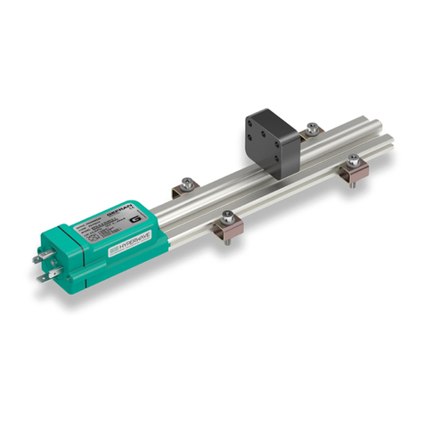
gefran WPA-F User manual

WPA-F /WRA-F
CONTACTLESS MAGNETOSTRICTIVE LINEAR POSITION TRANSDUCER
(PROFINET IO OUTPUT)
USER MANUAL
Cod. 80715 Edit. 03/2021 - ENG
CONTENTS
1. INTRODUCTION.....................................................................................................................................................................................2
2. INSTALLATION AND ELECTRICAL CONNECTIONS...........................................................................................................................2
2.1. General precautions...........................................................................................................................................................................2
2.2. Electrical installation ..........................................................................................................................................................................2
2.3. Status LEDS ......................................................................................................................................................................................4
3. MAIN COMMUNICATION FEATURES ...................................................................................................................................................5
4. GENERAL PROFILE ..............................................................................................................................................................................5
4.1. Process Data Structure .....................................................................................................................................................................5
4.2. Input modules ....................................................................................................................................................................................5
4.3. Modules Parameterization .................................................................................................................................................................6
4.3.1. Slot0 Parameterization............................................................................................................................................................6
4.3.2. Slot-n Parameterization...........................................................................................................................................................8
4.4. Info and statistic parameters..............................................................................................................................................................9
4.5. User commands.................................................................................................................................................................................9
4.6. Alarm values ......................................................................................................................................................................................9
4.7. Reading IO through acyclic data (see par. 4.1)................................................................................................................................10
5. ENCODER PROFILE............................................................................................................................................................................ 11
5.1. Process Data Structure ................................................................................................................................................................... 11
5.2. Modules Parameterization ...............................................................................................................................................................13
5.2.1. Standard Parameterization....................................................................................................................................................13
5.2.2. Manufacturer Parameterization.............................................................................................................................................15
5.3. Info and statistic parameters ...........................................................................................................................................................15
5.4. User commands ..............................................................................................................................................................................16
5.5. Alarm values ....................................................................................................................................................................................16
6. EXAMPLE OF PLC CONFIGURATION................................................................................................................................................17
6.1. General Prole conguration example.............................................................................................................................................17
6.2. Encoder Prole conguration example ............................................................................................................................................20

280715_MAN_WPA-F_WRA-F_03-2021_ENG
1. INTRODUCTION
WPA-F / WRA-F magnetostrictive transducer implements Pronet IO communication.
Pronet is a digital communication standard developed and maintained by PI (Probus and Pronet International).
The digital communication allows the transfer of data between the Device (the WPA-F/WRA-F transducer) and the Master (PLC)
through a network.
These data are:
●Process data, such as position, speed, status of the device
●Acyclic data, as parameterization, statistic, diagnostic data
Pronet standard provides a descriptor le called GSDML (General Station Description based on XML format).
This le allows a clear identication of the device and comprehension of data provided and exchanged.
Please refer to Gefran website for the download of GSDML les.
This manual is not designed to describe the “PROFINET” Fieldbus, as it is presumed the user is familiar with the same and will refer
if any updates are required to the above-mentioned standard or the ofcial PROFIBUS CONSORTIUM and PROFINET International
website (PI), http://www.probus.com/.
2. INSTALLATION AND ELECTRICAL CONNECTIONS
2.1. General precautions
The system must be used only in accordance with the required protection level.
The sensor must be protected against accidental knocks and used in accordance with the instrument’s ambient characteristics.
The sensors must be powered with non-distributed networks.
2.2. Electrical installation
The transducer must be grounded (normally through the machine body or equipment it is installed on).
Connect cables shielding to ground at cabinet side (control equipment or PLC).
To prevent interference, separate the power cables from signal cables.
The WPA-F/WRA-F transducer provides 3 connectors on its head:
● 2x M12 Female 4 poles D coded for Fieldbus connection (A-B in the image below)
● 1x M12 Male 4 poles A coded for bringing Power Supply to the device (C in the image below)
A B
C

80715_MAN_WPA-F_WRA-F_03-2021_ENG 3
●Port1 - Port 2 M12 4P Female D-coded connector connection
M12 Female 4 poles D coded
connector (Port1 – Port 2) Pinout
1Tx+
2Rx+
3Tx-
4Rx-
●Power Supply M12 4P Male A-coded connector connection
M12 Male 4 poles A coded
connector (Power Supply) Pinout
1V+
2NC
30V
4NC
We recommend the use of a CAT5 Ethernet cable or above STP or UTP. The maximum distance between two Ethernet network nodes
must be less than 100m.
For Power Supply use a shielded cable with metal connector and shield connected to connector case.
1
4
2
3
4
3
1
2
1
43
2
Profinet
Power Supply +24 Vdc
Device
Supervisor
Controller
Device
Device

480715_MAN_WPA-F_WRA-F_03-2021_ENG
2.3. Status LEDS
The WPA-F/WRA-F provides leds on transducer head in order to give diagnostic information compliant with standard and with added
manufacturer functionalities.
5 6
3 2
14
Led 1 (Red) Bus Fault Function
OFF No error on bus
ON No connection to controller
Flashing Waiting for parameterization
Led 2 (Green) System Fault + Signalling Function
OFF No system error
ON Application error
Flashing Signalling activated
Led 3 (Red) Application error Function
OFF No application error
ON Steady Position error
Flashing 0,5 Hz Power Supply error
Flashing 1 Hz Parameterization error
Flashing 2 Hz Temperature error
Flashing 4 Hz Internal communication error
Led 4 (Green) Power Supply Function
OFF No Power Supply
ON Power Supply ON
Led 5-6 (Red-Green) Link Activity Function
OFF No connection to next port
Green ON Connection to next port established
Green ON + Red Flashing Connection to next port established and communication active

80715_MAN_WPA-F_WRA-F_03-2021_ENG 5
3. MAIN COMMUNICATION FEATURES
Ethernet Baud Rate Max 100 Mbit/s
Data Transport Layer Ethernet II, IEEE 802.3
PNIO version 2.3
Real Time Communication RT & IRT Class 3
Prole General (Manufacturer) Prole or
Encoder Prole v 4.2 Class 4
Min Device Interval 1 ms (RT)
250us (IRT)
Address Discovery and Conguration Protocol
(DCP)
Default IP 0.0.0.0
Default Name “gefran-wxa-pn-gp” for General Prole
“gefran-wxa-pn-ep” for Encoder Prole
The WPA-F/WRA-F is available with different Communication Proles, according to ordering code:
● a standard IO prole, so called General Prole
● an Encoder Prole, compliant with v. 4.2 Class 4
Indipendently from prole the WPA-F/WRA-F is available with RT and IRT communication with min device interval up to 250 us (for
IRT only).
The Isochronous communication can be set inside the network tool (TIA Portal as an example), following the menus related to “Real
Time Settings”
4. GENERAL PROFILE
With this Prole up to 16 cursors are detectable and measured by the device.
4.1. Process Data Structure
The device WPA-F / WRA-F offers different process data and different conguration for process data.
The process variables available are:
Position (32 bit signed), for each of the cursors installed. For resolution refer to conguration options.
31..0
Position
Velocity (32 bit signed), for each of the cursors installed. For resolution refer to conguration options.
31..0
Velocity
Status (8byte), composed as following:
Voltage supply measured by device: 16bit (unsigned), 1mV resolution, 200mV sensitivity
Nr. of cursors detected: 8bit, change continuously according to nr. of cursors effectively detected
Bitmask of cursors congured: (5 byte), xed bitmask of cursors set during conguration
63…48 47…40 39..0
Voltage supply Nr. of cursors Bitmask of cursors congured
4.2. Input modules
The device WPA-F/WRA-F provides different modules containing process data. These modules are selectable in the input modules
catalog:
●Position: this module contains the position data of one cursor
●Velocity: this module contains the velocity data of one cursor
●Position and Velocity: this module contains the data of position and velocity of one cursor
● All Positions: this module contains the data of position of all the detectable cursors (16)
● All Velocities: this module contains the data of velocity of all the detectable cursors (16)
●Sensor Status: this module contains the data of status of the device (see process data structure)

680715_MAN_WPA-F_WRA-F_03-2021_ENG
4.3. Modules Parameterization
4.3.1. Slot0 Parameterization
In slot 0 the parameterization of the main module is present; herebelow the list of parameters available follows:
Index (dec) DataFormat Name Access Values: meaning (bold default)
1024 Unsigned32 Version of device parameter RO 2021/03/22
1025 Unsigned32 Resolution RW
500 : 0.5 microns
1000: 1 micron
2000: 2 microns
5000: 5 microns
10000: 10 microns
50000: 50 microns
100000: 100 microns
1026 Unsigned8 Filter mode RW
0: Filter type disabled
1: Filter type simple average (FIR)
2: Filter type endless response
average (IIR)
1027 Unsigned8 Filter nr. of samples RW 2..16
1028 Unsigned8 Velocity nr. of samples RW 2.8.16
1029 Unsigned8 Velocity Unit RW
0: Steps/1000 milliseconds
1: Steps/100 milliseconds
2: Steps/10 milliseconds
3: mm/s
1030 Unsigned8 Output Direction RW 0: Forward
1: Reverse
1031 Unsigned8 Number of congured Cursors RW 0..15: 1…16
1032 Unsigned8 Number of Cursors Alarm RW
0: Number of cursors different than
congured
1: Number of cursors higher than
congured
2: Number of cursors lower than
congured
3: Cursor alarm disabled
1033 Unsigned8 Voltage Supply Alarm RW
0: Supply voltage higher or lower
than limits
1: Supply voltage lower than limits
2: Supply voltage higher than limits
3: Voltage supply alarm disabled
1034 Integer32 Position offset of cursor 1 [um] RW 0
1035 Integer32 Position offset of cursor 2 [um] RW 0
1036 Integer32 Position offset of cursor 3 [um] RW 0
1037 Integer32 Position offset of cursor 4 [um] RW 0
1038 Integer32 Position offset of cursor 5 [um] RW 0
1039 Integer32 Position offset of cursor 6 [um] RW 0
1040 Integer32 Position offset of cursor 7 [um] RW 0
1041 Integer32 Position offset of cursor 8 [um] RW 0
1042 Integer32 Position offset of cursor 9 [um] RW 0
1043 Integer32 Position offset of cursor 10 [um] RW 0
1044 Integer32 Position offset of cursor 11 [um] RW 0
1045 Integer32 Position offset of cursor 12 [um] RW 0
1046 Integer32 Position offset of cursor 13 [um] RW 0
1047 Integer32 Position offset of cursor 14 [um] RW 0
1048 Integer32 Position offset of cursor 15 [um] RW 0
1049 Integer32 Position offset of cursor 16 [um] RW 0

80715_MAN_WPA-F_WRA-F_03-2021_ENG 7
Explanation:
● Version of device parameter: it’s a read only tag which denes the version of the parameter set
● Resolution: it denes the resolution for the position data, values allowed are: 0,5, 1, 2, 5, 10, 50, 100 um
● Filter mode: different types of lters on process data can be set by user:
-Disabled: no lter applied
-Simple average (FIR): only the number of samples corresponding to parameter “Filter nr. of samples” are considered
to dene the process data; the lter method used on these samples is moving average
-Endless response average (IIR): not only the number of samples corresponding to parameter “Filter nr. of samples” but
also the previous data are considered to dene the process output value
● Filter nr. of samples: it denes the number of samples used to lter the position data; values allowed are 2…16
● Velocity nr. of samples: it denes the number of position samples used to calculate velocity; values allowed are 2…16
● Velocity Unit: it denes the resolution of velocity data; values allowed are:
- 0: steps/1000ms
- 1: steps/100ms
- 2: steps/10ms
- 3: mm/s
● Output Direction: it denes the increasing direction of position and velocity data, values allowed are:
- Forward: it means that values increase positively from sensor head to the end of stroke
- Reverse: it means that values increase positively from sensor end of stroke towards the head
● Number of congured cursors: it denes the number of expected cursors on sensor stroke; this value will be responsible for
Position failure alarm in respect to the real number of cursors detected by the sensor; values allowed are 0…15 (corresponding
to cursors 1…16)
● Number of Cursors Alarm: it is possible to set an alarm referred to the number of cursors detected/congured; values allowed
are:
-0: Number of cursors detected different than congured
-1: Number of cursors detected higher than congured
-2: Number of cursors detected lower than congured
-3: Cursor alarm disabled
● Voltage Supply Alarm: the device measures its Voltage supply; it is possible to set an alarm referred to its level; values allowed
are:
- 0: Supply voltage higher or lower than limits
- 1: Supply voltage lower than limits
- 2: Supply voltage higher than limits
-3: Voltage supply alarm disabled
● Position offset of cursor n: it is possible to dene, for each of the possible 16 cursors, an offset value added to the
position value; the offset value is always expressed in um as an Int32

880715_MAN_WPA-F_WRA-F_03-2021_ENG
4.3.2. Slot-n Parameterization
According to the module/s selected below module 0 (see input modules) , a few further parameters are available for each type of
module:
● Position: it is possible to select which cursor position to measure (from 1 to 16)
Index (dec) DataFormat Name Access Values: meaning (bold default)
1050 Unsigned8 PositionParam.MagnetToMeasure_SL1 RW 0..15: 1…16
1051 Unsigned8 PositionParam.MagnetToMeasure_SL2 RW 0..15: 1…16
1052 Unsigned8 PositionParam.MagnetToMeasure_SL3 RW 0..15: 1…16
1053 Unsigned8 PositionParam.MagnetToMeasure_SL4 RW 0..15: 1…16
1054 Unsigned8 PositionParam.MagnetToMeasure_SL5 RW 0..15: 1…16
1055 Unsigned8 PositionParam.MagnetToMeasure_SL6 RW 0..15: 1…16
1056 Unsigned8 PositionParam.MagnetToMeasure_SL7 RW 0..15: 1…16
1057 Unsigned8 PositionParam.MagnetToMeasure_SL8 RW 0..15: 1…16
1058 Unsigned8 PositionParam.MagnetToMeasure_SL9 RW 0..15: 1…16
1059 Unsigned8 PositionParam.MagnetToMeasure_SL10 RW 0..15: 1…16
1060 Unsigned8 PositionParam.MagnetToMeasure_SL11 RW 0..15: 1…16
1061 Unsigned8 PositionParam.MagnetToMeasure_SL12 RW 0..15: 1…16
1062 Unsigned8 PositionParam.MagnetToMeasure_SL13 RW 0..15: 1…16
1063 Unsigned8 PositionParam.MagnetToMeasure_SL14 RW 0..15: 1…16
1064 Unsigned8 PositionParam.MagnetToMeasure_SL15 RW 0..15: 1…16
1065 Unsigned8 PositionParam.MagnetToMeasure_SL16 RW 0..15: 1…16
● Velocity: it is possible to select which cursor velocity to measure (from 1 to 16)
Index (dec) DataFormat Name Access Values: meaning (bold default)
1066 Unsigned8 VelocityParam.MagnetToMeasure_SL1 RW 0..15: 1…16
1067 Unsigned8 VelocityParam.MagnetToMeasure_SL2 RW 0..15: 1…16
1068 Unsigned8 VelocityParam.MagnetToMeasure_SL3 RW 0..15: 1…16
1069 Unsigned8 VelocityParam.MagnetToMeasure_SL4 RW 0..15: 1…16
1070 Unsigned8 VelocityParam.MagnetToMeasure_SL5 RW 0..15: 1…16
1071 Unsigned8 VelocityParam.MagnetToMeasure_SL6 RW 0..15: 1…16
1072 Unsigned8 VelocityParam.MagnetToMeasure_SL7 RW 0..15: 1…16
1073 Unsigned8 VelocityParam.MagnetToMeasure_SL8 RW 0..15: 1…16
1074 Unsigned8 VelocityParam.MagnetToMeasure_SL9 RW 0..15: 1…16
1075 Unsigned8 VelocityParam.MagnetToMeasure_SL10 RW 0..15: 1…16
1076 Unsigned8 VelocityParam.MagnetToMeasure_SL11 RW 0..15: 1…16
1077 Unsigned8 VelocityParam.MagnetToMeasure_SL12 RW 0..15: 1…16
1078 Unsigned8 VelocityParam.MagnetToMeasure_SL13 RW 0..15: 1…16
1079 Unsigned8 VelocityParam.MagnetToMeasure_SL14 RW 0..15: 1…16
1080 Unsigned8 VelocityParam.MagnetToMeasure_SL15 RW 0..15: 1…16
1081 Unsigned8 VelocityParam.MagnetToMeasure_SL16 RW 0..15: 1…16
● Position and Velocity: it is possible to select which cursor position+velocity to measure (from 1 to 16)
Index (dec) DataFormat Name Access Values: meaning (bold default)
1082 Unsigned8 PosVelParam.MagnetToMeasure_SL1 RW 0..15: 1…16
1083 Unsigned8 PosVelParam.MagnetToMeasure_SL2 RW 0..15: 1…16
1084 Unsigned8 PosVelParam.MagnetToMeasure_SL3 RW 0..15: 1…16
1085 Unsigned8 PosVelParam.MagnetToMeasure_SL4 RW 0..15: 1…16
1086 Unsigned8 PosVelParam.MagnetToMeasure_SL5 RW 0..15: 1…16
1087 Unsigned8 PosVelParam.MagnetToMeasure_SL6 RW 0..15: 1…16
1088 Unsigned8 PosVelParam.MagnetToMeasure_SL7 RW 0..15: 1…16
1089 Unsigned8 PosVelParam.MagnetToMeasure_SL8 RW 0..15: 1…16
1090 Unsigned8 PosVelParam.MagnetToMeasure_SL9 RW 0..15: 1…16
1091 Unsigned8 PosVelParam.MagnetToMeasure_SL10 RW 0..15: 1…16
1092 Unsigned8 PosVelParam.MagnetToMeasure_SL11 RW 0..15: 1…16
1093 Unsigned8 PosVelParam.MagnetToMeasure_SL12 RW 0..15: 1…16
1094 Unsigned8 PosVelParam.MagnetToMeasure_SL13 RW 0..15: 1…16
1095 Unsigned8 PosVelParam.MagnetToMeasure_SL14 RW 0..15: 1…16
1096 Unsigned8 PosVelParam.MagnetToMeasure_SL15 RW 0..15: 1…16
1097 Unsigned8 PosVelParam.MagnetToMeasure_SL16 RW 0..15: 1…16

80715_MAN_WPA-F_WRA-F_03-2021_ENG 9
●Sensor status: no parameters
●All Positions: no parameters
●All Velocities: no parameters
4.4. Info and statistic parameters
The device WPA-F/WRA-F provides a list of parameters which is possible to readout in order to receive some information and useful
statistic data from the device.
Index (dec) DataFormat Name Access UM Range/Format
3073 Unsigned32 OperatingTimeCounter RO [0,1h]
3075 Int16 Temperature RO [0,1°C]
3076 Int16 TemperatureMax RO [0,1°C]
4096 Unsigned32 NominalSpan RO [um] 0…4000000
4097 Unsigned32 SerialNumber RO YYWWNNNN
4098 Unsigned32 CalibrationDate RO YYYYMMDD
4099 Unsigned32 SensorSwVersion RO YYYYMMDD
Explanation:
● Operating time counter: the working time of the device is stored in non volatile memory since rst power on or since last reset
command (see par 4.5); this increasing counter has resolution 0,1h (6 min)
● Temperature: it’s the temperature measured internally by electronics, with 0,1°C resolution; this value is volatile
● Temperature Max: it’s the maximum temperature measured internally by electronics, with 0,1°C resolution, stored in non vol-
atile memory, since rst power on or since last reset command (see par 4.5)
● Nominal Span: it’s the full range stroke of the device as dened in the ordering code, with 1um resolution
● Serial Number: it’s the Serial Number as reported on device nameplate
● Calibration Date: it reports the date of calibration of device in the coding YYYYMMDD
●SensorSWVersion: SW version of the processor managing the measure
4.5. User commands
The device WPA-F/WRA-F provides a list of commands which the user can act in case of
Index (dec) DataFormat Name Access Data to Write
6144 Unsigned8 ResetUserStatisticsData WO 1
6145 Unsigned8 StoreStatisticsDat WO 1
Explanation:
●ResetUserStatisticsData: through this command the user can request the reset of following statistics data:
-OperatingTimeCounter
-TemperatureMax
●StoreStatisticsData: through this command the user can force an immediate storage of statistics parameters (OperatingTime-
Counter and TemperatureMax), otherwise the auto saving happens every 6 min
4.6. Alarm values
In case of Diagnostics events the WPA-F / WRA-F communicates through Pronet alarm messages the following:
Alarm ID Meaning
16 Parameterization Error
17 Supply Voltage Error
27 Number of cursors Error
5 Temperature Error
19 Internal Communication Error
Explanation:
●Parameterization Error: the device received an uncorrect parameterization
● Supply Voltage Error: the error rises according to the conguration of parameter “Voltage Supply Alarm”
● Number of cursors Error: the error rises according to the conguration of parameter “Number of Cursors Alarm”
●Temperature Error: the error rises if Electronics temperature overtakes the working temperature limit
● Internal Communication Error: the error rises if a failure in internal communication between processors happens

10 80715_MAN_WPA-F_WRA-F_03-2021_ENG
4.7. Reading IO through acyclic data (see par. 4.1)
Through acyclic communication it is possible to read out Process data as well
Address (dec) Data Format Name Access Value range
0 Integer32 HostProcessData.Position01 RO
1 Integer32 HostProcessData.Position02 RO
2 Integer32 HostProcessData.Position03 RO
3 Integer32 HostProcessData.Position04 RO
4 Integer32 HostProcessData.Position05 RO
5 Integer32 HostProcessData.Position06 RO
6 Integer32 HostProcessData.Position07 RO
7 Integer32 HostProcessData.Position08 RO
8 Integer32 HostProcessData.Position09 RO
9 Integer32 HostProcessData.Position10 RO
10 Integer32 HostProcessData.Position11 RO
11 Integer32 HostProcessData.Position12 RO
12 Integer32 HostProcessData.Position13 RO
13 Integer32 HostProcessData.Position14 RO
14 Integer32 HostProcessData.Position15 RO
15 Integer32 HostProcessData.Position16 RO
16 Integer32 HostProcessData.Speed01 RO
17 Integer32 HostProcessData.Speed02 RO
18 Integer32 HostProcessData.Speed03 RO
19 Integer32 HostProcessData.Speed04 RO
20 Integer32 HostProcessData.Speed05 RO
21 Integer32 HostProcessData.Speed06 RO
22 Integer32 HostProcessData.Speed07 RO
23 Integer32 HostProcessData.Speed08 RO
24 Integer32 HostProcessData.Speed09 RO
25 Integer32 HostProcessData.Speed10 RO
26 Integer32 HostProcessData.Speed11 RO
27 Integer32 HostProcessData.Speed12 RO
28 Integer32 HostProcessData.Speed13 RO
29 Integer32 HostProcessData.Speed14 RO
30 Integer32 HostProcessData.Speed15 RO
31 Integer32 HostProcessData.Speed16 RO
32 Unsigned16 PowerSupply RO
33 Unsigned8 NumberOfCursors RO
34 Unsigned8 BitMask[0] RO
35 Unsigned8 BitMask[1] RO
36 Unsigned8 BitMask[2] RO
37 Unsigned8 BitMask[3] RO
38 Unsigned8 BitMask[4] RO

80715_MAN_WPA-F_WRA-F_03-2021_ENG 11
5. ENCODER PROFILE
5.1. Process Data Structure
The device WPA-F / WRA-F with specic ordering code requested communicates as an Encoder device compliant to Pronet Encoder
Prole ver 4.2 class 4.
With this Prole only one cursor is detectable and measured by the device.
With this Prole communication modules are standardized and called Telegrams; different telegrams are available for the WPA-F /
WRA-F Encoder.
●Standard Telegram 81
This telegram foresees 4 bytes of output (Master to Device) and 12 bytes of input (Device to Master)
OUTPUT DATA
Word Data 1 2
Byte Data 0 1 2 3
Output
value STW2_ENC G1_STW
Meaning
Encoder
control word
2
Sensor
control
word
INPUT DATA
Word Data 1 2 3 4 5 6
Byte Data 0 1 2 3 4 5 6 7 8 9 10 11
Output
value ZSW2_ENC G1_ZSW G1_XIST1 G1_XIST2
Meaning Status word
2
Status
word Position value Position value 2
●Standard Telegram 82
This telegram foresees 4 bytes of output (Master to Device) and 14 bytes of input (Device to Master)
OUTPUT DATA
Word Data 1 2
Byte Data 0 1 2 3
Output
value STW2_ENC G1_STW
Meaning
Encoder
control word
2
Sensor
control
word
INPUT DATA
Word Data 1 2 3 4 5 6 7
Byte Data 0 1 2 3 4 5 6 7 8 9 10 11 12 13
Output
value ZSW2_ENC G1_ZSW G1_XIST1 G1_XIST2 NIST_A
Meaning Status word
2
Status
word Position value Position value 2 Velocity

12 80715_MAN_WPA-F_WRA-F_03-2021_ENG
●Standard Telegram 83
This telegram foresees 4 bytes of output (Master to Device) and 16 bytes of input (Device to Master)
OUTPUT DATA
Word Data 1 2
Byte Data 0 1 2 3
Output
value STW2_ENC G1_STW
Meaning
Encoder
control word
2
Sensor
control
word
INPUT DATA
Word Data 1 2 3 4 5 6 7 8
Byte Data 0 1 2 3 4 5 6 7 8 9 10 11 12 13 14 15
Output
value ZSW2_ENC G1_ZSW G1_XIST1 G1_XIST2 NIST_B
Meaning Status word
2
Status
word Position value Position value 2 Velocity
●Standard Telegram 84
This telegram foresees 4 bytes of output (Master to Device) and 20 bytes of input (Device to Master)
OUTPUT DATA
Word Data 1 2
Byte Data 0 1 2 3
Output
value STW2_ENC G1_STW
Meaning
Encoder
control word
2
Sensor
control
word
INPUT DATA
Word Data 1 2 3 4 5 6 7 8 9 10
Byte Data 0 1 2 3 4 5 6 7 8 9 10 11 12 13 14 15 16 17 18 19
Output
value ZSW2_ENC G1_ZSW G1_XIST3 G1_XIST2 NIST_B
Meaning Status word
2
Status
word Position value Position value 2 Velocity
Denition of contents:
● STW2_ENC = Encoder control word 2
Bit Function Notes
0XIST_PRESET_CONTROL
1…6 Reserved for prole
7Fault Acknowledge
8…9 Reserved for vendor specic extensions Not used
10 Control by PLC
11 Reserved for vendor specic extensions Not used
12…15 Controller Sign-Of-Life

80715_MAN_WPA-F_WRA-F_03-2021_ENG 13
● G1_STW = Sensor control word
Bit Function Notes
0…7 Function requests: Reference mark search, measurement on the y
8…10 Reserved
11 Home position mode
12 Request set/shift of home position
13 Request absolute value cyclically
14 Activate parking sensor
15 Acknowledging a sensor error
● ZSW2_ENC = Status word 2
Bit Function Notes
0XIST_PRESET_ACK
1XIST_VALID
2NIST_VALID
3Fault Present / No Fault
4…6 Reserved for prole
7Warning Present / No Warning
8Reserved for vendor specic extensions
9Control requested
10,11 Reserved for vendor specic extensions
12…15 Encoder Sign-Of-Life
● G1_ZSW = Sensor status word
Bit Function Notes
0…7 Function status: Reference mark search, measurement on the y
8Probe 1 deected
9Probe 2 deected
10 Reserved, set to zero
11 Requirement of error acknowledgement detected
12 Set/shift of home position executed
13 Transmit absolute value cyclically (absolute encoders only)
14 Parking sensor active
15 Sensor error
● G1_XIST1 = Position value 1 (32bit)
● G1_XIST2 = Position value 2 (32bit)
● G1_XIST3 = Position value (64bit)
● NIST_A = Velocity (16bit)
● NIST_B = Velocity (32bit)
5.2. Modules Parameterization
With Encoder Prole Slot 0 and 1 are already selected; in Slot 1 a list of standard and manufacturer specic parameters is present
5.2.1. Standard Parameterization
Index (dec) DataFormat Name Access Values: meaning (bold default)
65004.0 Bit type Code Sequence RW 0: CW (forward)
1: CCW (reverse)
65004.1 Bit type Class 4 functionality RW 1: Enable
0: Disable
65004.2 Bit type G1_XIST1 Preset control RW 0: Enable
1: Disable
65004.3 Bit type Scaling function control RW 1: Enable
0: Disable
65004.4 Bit type Alarm channel control RW 1: Enable
0: Disable

14 80715_MAN_WPA-F_WRA-F_03-2021_ENG
Index (dec) DataFormat Name Access Values: meaning (bold default)
65004.5 Bit type V3.1 Compatibility mode RW 0: Enable
1: Disable
65006 Unsigned32 Measurement step RW
500 : 0.5 microns
1000: 1 micron
2000: 2 microns
5000: 5 microns
10000: 10 microns
50000: 50 microns
100000: 100 microns
65007 Unsigned32 Measurement range RW
925 Unsigned8 Maximum master sign-of-life failures RW
60001 Unsigned8 Velocity Unit RW
0: Steps/1000 milliseconds
1: Steps/100 milliseconds
2: Steps/10 milliseconds
3: mm/s
4: N2/N4 Normalised
60000 oat32 Velocity reference value RW
65005 Unsigned16 Parameter Control RW
Explanation:
● Code Sequence: it denes the increasing direction of position and velocity data, values allowed are:
-0: Clockwise: it means that values increase positively from sensor head to the end of stroke
-1: CounterClockwise: it means that values increase positively from sensor end of stroke towards the head
● Class 4 functionality: this parameter enables/disables the use of parameters “Code sequence”, “G1_XIST1 preset control”,
“Scaling function”, “measuring step”, “measuring range”, “velocity unit”. If this parameter is disabled the above mentioned pa-
rameters are not taken into account and the device by default measures with:
-Clockwise
- 1um resolution
-No preset set
If “G1_XIST1 preset control” is activated this will affect G1_XIST1, G1_XIST2 and G1_XIST3
● G1_XIST1 Preset control: this parameter denes if preset for G1_XIST1 is active or not
● Scaling function control: this parameter denes if resolution of device can be changed or not
● Alarm channel control: this parameter denes if the alarm channel is active or not; it’ s available only in compatibility mode and
can be activated only in compatibility mode
● V3.1 Compatibility mode: this parameter denes if the sensor works as a 3.1 compatible encoder or not; if this parameter is
enabled the following parameters are affected:
Functions V3.1 Compatibility mode enabled V3.1 Compatibility mode disabled
STW2_ENC Ignored Supported
User parameter alarm channel control Supported Not supported
P965 Prole Version 31 (V3.1) 42 (V4.2)
● Measurement step: it denes the resolution for the position data, values allowed are: 0,5, 1, 2, 5, 10, 50, 100 um
● Measurement range: it denes the limit of measuring range in measuring steps, if “Scaling function” is activated
● Maximum Master Sign-of-Life failures: it denes the number of allowed failures of master sign-of-life; it can be used only in
compatibility mode
● Velocity Unit: it denes the resolution of velocity data; values allowed are:
- 0: steps/1000ms
- 1: steps/100ms
- 2: steps/10ms
- 3: mm/s
-4: N2/N4 Normalised
● Velocity reference value: it denes the speed value for 100% for N2/N4 normalised speed signals (NIST). See also P60001
● Parameter Control: it controls the run-up initialization of the encoder parameters and the online access on the encoder param-
eters via the BMP parameter channel

80715_MAN_WPA-F_WRA-F_03-2021_ENG 15
5.2.2. Manufacturer Parameterization
Index (dec) DataFormat Name Access Values: meaning (bold default)
1026 Unsigned8 Filter mode RW
0: Filter type disabled
1: Filter type simple average (FIR)
2: Filter type endless response average (IIR)
1027 Unsigned8 Filter nr. of samples RW 2..16
1028 Unsigned8 Velocity nr. of samples RW 2.8.16
1032 Unsigned8 Number of Cursors Alarm RW
0: Number of cursors different than one
1: Number of cursors higher than one
2: Number of cursors lower than one
3: Cursor alarm disabled
1033 Unsigned8 Voltage Supply Alarm RW
0: Supply voltage higher or lower than limits
1: Supply voltage lower than limits
2: Supply voltage higher than limits
3: Voltage supply alarm disabled
Explanation:
● Filter mode: different types of lters on process data can be set by user:
-Disabled: no lter applied
-Simple average (FIR): only the number of samples corresponding to parameter “Filter nr. of samples” are considered
to dene the process data; the lter method used on these samples is moving average
-Endless response average (IIR): not only the number of samples corresponding to parameter “Filter nr. of samples” but
also the previous data are considered to dene the process output value
● Filter nr. of samples: it denes the number of samples used to lter the position data; values allowed are 2…16
● Velocity nr. of samples: it denes the number of position samples used to calculate velocity; values allowed are 2…16
● Number of Cursors Alarm: it is possible to set an alarm referred to the number of cursors detected; values allowed are:
-0: Number of cursors detected different than one
-1: Number of cursors detected higher than one
-2: Number of cursors detected lower than one
-3: Cursor alarm disabled
● Voltage Supply Alarm: the device measures its Voltage supply; it is possible to set an alarm referred to its level; values allowed
are:
- 0: Supply voltage higher or lower than limits
- 1: Supply voltage lower than limits
- 2: Supply voltage higher than limits
-3: Voltage supply alarm disabled
5.3. Info and statistic parameters
The device WPA-F/WRA-F provides a list of parameters which is possible to readout in order to receive some information and useful
statistic data from the device.
Index (dec) DataFormat Name Access UM Range / Format
3073 Unsigned32 OperatingTimeCounter RO [0,1h]
3075 Int16 Temperature RO [0,1°C]
3076 Int16 TemperatureMax RO [0,1°C]
4096 Unsigned32 NominalSpan RO [um] 0…4000000
4097 Unsigned32 SerialNumber RO YYWWNNNN
4098 Unsigned32 CalibrationDate RO YYYYMMDD
4099 Unsigned32 SensorSwVersion RO YYYYMMDD
Explanation:
● Operating time counter: the working time of the device is stored in non volatile memory since rst power on or since last reset
command (see par 5.4); this increasing counter has resolution 0,1h (6 min)
● Temperature: it’s the temperature measured internally by electronics, with 0,1°C resolution; this value is volatile
● TemperatureMax: it’s the maximum temperature measured internally by electronics, with 0,1°C resolution, stored in non vola-
tile memory, since rst power on or since last reset command (see par 5.4)

16 80715_MAN_WPA-F_WRA-F_03-2021_ENG
● Nominal Span: it’s the full range stroke of the device as dened in the ordering code, with 1um resolution
● Serial Number: it’s the Serial Number as reported on device nameplate
● Calibration Date: it reports the date of calibration of device in the coding YYYYMMDD
●SensorSWVersion: SW version of the processor managing the measure
5.4. User commands
The device WPA-F/WRA-F provides a list of commands which the user can act in case of
Index (dec) DataFormat Name Access Data to Write
6144 Unsigned8 ResetUserStatisticsData WO 1
6145 Unsigned8 StoreStatisticsData WO 1
Explanation:
●ResetUserStatisticsData: through this command the user can request the reset of following statistics data:
-OperatingTimeCounter
-TemperatureMax
●StoreStatisticsData: through this command the user can force an immediate storage of statistics parameters (OperatingTime-
Counter and TemperatureMax), otherwise the auto saving happens every 6 min
5.5. Alarm values
In case of Diagnostics events the WPA-F / WRA-F communicates through Pronet alarm messages the following:
Alarm ID Meaning
36865 Supply Voltage Above limits
36866 Supply Voltage Below limits
36874 Number of cursors Error
36869 Temperature Error
36875 Internal Communication Error
Explanation:
● Supply Voltage Above limits: the error rises if the Voltage Supply increase above limits
● Supply Voltage Below limits: the error rises if the Voltage Supply falls below limits
● Number of cursors Error: the error rises according to the conguration of parameter “Number of Cursors Alarm”
●Temperature Error: the error rises if Electronics temperature overtakes the working temperature limit
● Internal Communication Error: the error rises if a failure in internal communication between processors happens

80715_MAN_WPA-F_WRA-F_03-2021_ENG 17
6. EXAMPLE OF PLC CONFIGURATION
In the following some examples of integration of WPA-F/WRA-F into a PLC system are given, both for General Prole and Encoder
Prole, both RT and IRT communication. TIA Portal is taken as an example.
First of all the right GSDML le of device has to be installed into the catalog of TIA Portal:
● GSDML-Vx.xx-GEFRAN-WxA_PN_GP-yyyymmdd : for General Prole
● GSDML-Vx.xx-GEFRAN-WxA_PN_EP-yyyymmdd : for Encoder Prole
6.1. General Profile configuration example
After having loaded the GSDML into the catalog, the device has the default name “gefran-wxa-pn-gp”; the user can change it accord-
ing to his application.
It is possible to select and drag the desired module / modules related to position (1..16), velocity (1..16), all positions, all velocities,
status.
In Real time settings it is possible to set the RT class: RT or IRT

18 80715_MAN_WPA-F_WRA-F_03-2021_ENG
If IRT communication is selected the respective ag in Isochronous mode page must be checked
And the network topology must be arranged setting the Sync domain of the devices composing the network

80715_MAN_WPA-F_WRA-F_03-2021_ENG 19
According to the loaded module/s it’s needed to select the cursor to measure inside Module parameters.
Modul Sensor status does not have parameters to select.
In module parameters of the main module (Slot 0) it’s possible to select parameterization for the whole device, as well as setting of
offset for each cursor

20 80715_MAN_WPA-F_WRA-F_03-2021_ENG
6.2. Encoder Profile configuration example
After having loaded the GSDML into the catalog, the device has the default name “gefran-wxa-pn-ep”; the user can change it accord-
ing to his application.
It is possible to select and drag the desired module related to different telegrams available for the prole.
In Real time settings it is possible to set the RT class: RT or IRT
This manual suits for next models
1
Table of contents
Other gefran Transducer manuals