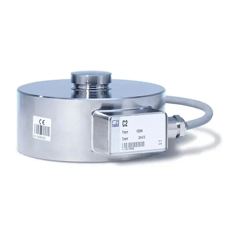
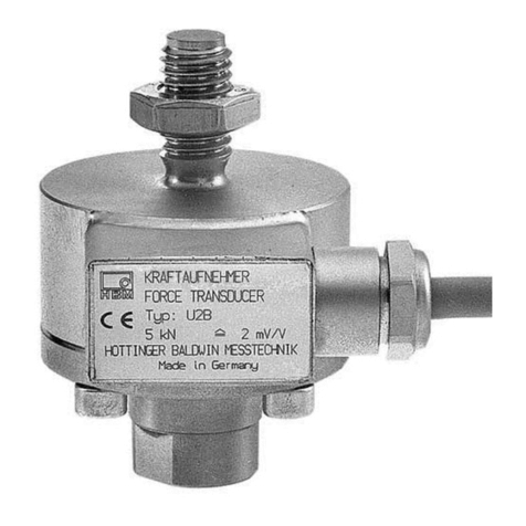
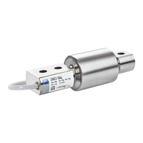
HBM Paceline CFT User manual

A2529-2.0 en/de/fr
Piezoelectric
force transducer
Piezoelektrischer
Kraftaufnehmer
Capteurs de charge
piézo-électrique
CFT
Mounting instructions
Montageanleitung
Notice de montage

English Page 3 - 18. . . . . . . . . . . . . . . . . . . . . . . . . . . . . . . . . . . . . . . . . . . . . . . . .
Deutsch Seite 19 - 32. . . . . . . . . . . . . . . . . . . . . . . . . . . . . . . . . . . . . . . . . . . . . . .
Français Page 33 - 48. . . . . . . . . . . . . . . . . . . . . . . . . . . . . . . . . . . . . . . . . . . . . . .

3
CFT
A2529-2.0 en/de/fr HBM
Contents Page
English
Safety instructions 4. . . . . . . . . . . . . . . . . . . . . . . . . . . . . . . . . . . . . . . . . . . . . .
1 Scope of supply 8. . . . . . . . . . . . . . . . . . . . . . . . . . . . . . . . . . . . . . . . . . . . .
2 Application instructions 9. . . . . . . . . . . . . . . . . . . . . . . . . . . . . . . . . . . . . .
3 Conditions on site 10. . . . . . . . . . . . . . . . . . . . . . . . . . . . . . . . . . . . . . . . . . .
3.1 Ambient temperature 10. . . . . . . . . . . . . . . . . . . . . . . . . . . . . . . . . . . . .
3.2 Moisture and humidity 11. . . . . . . . . . . . . . . . . . . . . . . . . . . . . . . . . . . .
3.3 Deposits 11. . . . . . . . . . . . . . . . . . . . . . . . . . . . . . . . . . . . . . . . . . . . . . . .
4 Structure and principle of operation 12. . . . . . . . . . . . . . . . . . . . . . . . . . .
5 Mechanical installation 13. . . . . . . . . . . . . . . . . . . . . . . . . . . . . . . . . . . . . . .
5.1 Important precautions during installation 13. . . . . . . . . . . . . . . . . . . .
5.2 General installation guidelines 13. . . . . . . . . . . . . . . . . . . . . . . . . . . . .
5.3 Installation for compressive loading 14. . . . . . . . . . . . . . . . . . . . . . . .
6 Connection 16. . . . . . . . . . . . . . . . . . . . . . . . . . . . . . . . . . . . . . . . . . . . . . . . . .
7 Specifications (VDI/VDE2638 standards) 17. . . . . . . . . . . . . . . . . . . . . . .
8 Dimensions (in mm; 1 mm = 0.03937 inches) 18. . . . . . . . . . . . . . . . . . .

CFT
4
A2529-2.0 en/de/frHBM
Safety instructions
The supply connection, as well as the signal and sense leads, must be
installed in such a way that electromagnetic interference does not adversely
affect device functionality (HBM recommendation: ”Greenline shielding
design”, downloadable from the Internet at http://www.hbm.com/Greenline).
Automation equipment and devices must be covered over in such a way that
adequate protection or locking against unintentional actuation is provided
(such as access checks, password protection, etc.).
When devices are working in a network, these networks must be designed in
such a way that malfunctions in individual nodes can be detected and shut
down.
Safety precautions must be taken both in terms of hardware and software, so
that a line break or other interruptions to signal transmission, such as via the
bus interfaces, do not cause undefined states or loss of data in the
automation device.
Appropriate use
The CFT piezoelectric force transducer is intended for compressive force
measurements in test benches, press‐fit processes, test and inspection
equipment and presses. Use for any additional purpose shall be deemed to
be not appropriate.
In the interests of safety, the transducer should only be operated as described
in the Mounting Instructions. It is also essential to comply with the legal and
safety requirements for the application concerned during use. The same
applies to the use of accessories.
The force transducer is not a safety element within the meaning of appropriate
use. For safe and trouble‐free operation, this transducer must not only be
correctly transported, stored, sited and mounted but must also be carefully
operated and maintained.
Each time, before starting up the equipment, you must first run a project
planning and risk analysis that takes into account all the safety aspects of
automation technology. This particularly concerns personal and machine
protection.
Additional safety precautions must be taken in plants where malfunctions
could cause major damage, loss of data or even personal injury. In the event
of a fault, these precautions establish safe operating conditions.
This can be done, for example, by mechanical interlocking, error signaling,
limit value switches, etc.

5
CFT
A2529-2.0 en/de/fr HBM
General dangers of failing to follow the safety instructions
The CFT piezoelectric force transducer is state of the art and reliable.
The transducer complies with the state of the art and is safe to operate. If the
transducer is used and operated inappropriately by untrained personnel,
residual dangers may arise.
Anyone responsible for installing, starting up, maintaining or repairing the
transducer needs to have read and understood the operating manual and in
particular the safety instructions.
Remaining dangers
The scope of supply and performance of the force transducer covers only a
small area of force measurement technology. In addition, equipment planners,
installers and operators should plan, implement and respond to the safety en
gineering considerations of force measurement technology in such a way as
to minimize remaining dangers. Prevailing regulations must be complied with
at all times. There must be reference to the remaining dangers associated
with force measurement technology.
Remaining dangers are indicated in these Mounting Instructions by the
following symbols:
Symbol: WARNING
Meaning: Dangerous situation
Warns of a potentially dangerous situation in which failure to comply with
safety requirements can result in death or serious physical injury.
Symbol: ATTENTION
Meaning: Possibly dangerous situation
Warns of a potentially dangerous situation in which failure to comply with
safety requirements could result in damage to property or some form of
physical injury.
Symbol: NOTE
Means that important information about the product or its handling is being
given.

CFT
6
A2529-2.0 en/de/frHBM
Symbol:
Meaning: CE mark
The CE mark enables the manufacturer to guarantee that the product
complies with the requirements of the relevant EC directives (the Declaration
of Conformity can be found at http://www.hbm.com/HBMdoc).
Symbol:
Meaning: Statutory marking requirements for waste disposal
National and local regulations regarding the protection of the environment and
recycling of raw materials require old equipment to be separated from regular
domestic waste for disposal.
For more detailed information on disposal, please contact the local authorities
or the dealer from whom you purchased the product.
Conversions and modifications
The force transducer must not be modified from the design or safety
engineering point of view except with our express agreement. Any
modification shall exclude all liability on our part for any damage resulting
therefrom.
The product is delivered from the factory with a fixed hardware and software
configuration. Changes can only be made within the possibilities documented
in the manuals.
Qualified personnel
The transducer may be used by qualified personnel only; the specifications
and the special safety regulationsneed to be followed in all cases.
This means people who meet at least one of the three following requirements:
-Knowledge of the safety concepts of automation technology is a
requirement and as project personnel, you must be familiar with these
concepts.
-As automation plant operating personnel, you have been instructed how to
handle the machinery and are familiar with the operation of the equipment
and technologies described in this documentation.

7
CFT
A2529-2.0 en/de/fr HBM
-As commissioning engineers or service engineers, you have successfully
completed the training to qualify you to repair the automation systems.
You are also authorized to activate, to ground and label circuits and
equipment in accordance with safety engineering standards.
It is also essential to comply with the appropriate legal and safety regulations
for the application concerned during use. The same applies to the use of ac
cessories.
Qualified personnel means personel familiar with the installation, fitting,
start-up and operation of the product, and trained according to their job.
Conditions at the place of installation
Protect the force transducer from moisture and dampness or weather
conditions such as rain, snow, ice and salt water.
To comply with EN 61326-1, para. 3.6 , the connecting leads of the CFT force
measurement chain must not be more than 30 m in length (if run in a building)
and must not exit the building.
Maintenance
The CFT piezoelectric force transducer is maintenance free.
Accident prevention
The prevailing accident prevention regulations must be taken into account,
even though the nominal (rated) force values in the destructive range are well
in excess of the full scale value.

CFT
8
A2529-2.0 en/de/frHBM
1 Scope of supply
Order number
1‐CFT / 5 kN CFT/ 5 kN piezoelectric force transducer
1‐CFT / 20 kN CFT/ 20 kN piezoelectric force transducer
1‐CFT / 50 kN CFT / 50 kN piezoelectric force transducer
1‐CFT / 70 kN CFT / 70 kN piezoelectric force transducer
1‐CFT / 120 kN CFT / 120 kN piezoelectric force transducer
To be ordered separately:
1-KAB143-3 Transducer connection cable (Material: PFTE), length 3 m;
UNF10-32 connector on both sides

9
CFT
A2529-2.0 en/de/fr HBM
2 Application instructions
Piezoelectric force transducers of the CFT type series are suitable for
measuring compressive forces. Because they provide highly accurate
dynamic and quasi‐static force measurements, they must be handled very
carefully. Particular care must be taken when transporting and installing the
devices. Dropping or knocking the transducers may cause permanent
damage.
The transducers are extremely rigid and have a high natural frequency.
The specifications list the permissible limits for mechanical, thermal and
electrical stress. It is essential that these are taken into account when
planning the measuring set‐up, during installation and ultimately, during
operation.

CFT
10
A2529-2.0 en/de/frHBM
3 Conditions on site
ATTENTION
The insulation resistance is crucial for piezoelectric transducers; it
should be greater than 1013 ohms. To obtain this value , all the
plug connections have to be kept thoroughly clean. A positive or
negative signal drift of the nominal (rated) output signal indicates
insufficient insulation resistance. The plug connection contacts
should then be cleaned with a clean, lint‐free cloth and a cleaning
agent (petroleum ether, isopropanol).
ATTENTION
Protect the transducer plug against pollution and under no
circumstances touch the connectors (plug face) with your
hand. The supplied cover should always be in place when the
connection is not in use.
Once mounted, the connection cable should remain connected to the
transducer, if possible.
3.1 Ambient temperature
The temperature has little effect on the output signal. To obtain optimum mea
surement results, the nominal (rated) temperature range must be observed.
Temperature‐related measurement errors are caused by heating on one side
(e.g. radiant heat) or by cooling. A radiation shield and all‐round thermal in
sulation produce noticeable improvements, but must not be allowed to form a
force shunt.

11
CFT
A2529-2.0 en/de/fr HBM
3.2 Moisture and humidity
Moisture and humidity or a tropical climate are to be avoided. When the
connection cable is properly connected to the force transducer/charge
amplifier, the CFT force transducer has degree of protection IP65 per EN
60529.
3.3 Deposits
Dust, dirt and other foreign matter must not be allowed to accumulate
sufficiently to divert some of the measuring force onto the housing, thus
invalidating the measured value (force shunt).

CFT
12
A2529-2.0 en/de/frHBM
4 Structure and principle of operation
The CFT force transducers operate in accordance with the piezoelectric
principle.
Compressive forces are transmitted to measuring elements sensitive to force
via pre‐stressed mounting bases. These separate the electrical charges in
proportion to the force displacement. A charge amplifier then converts these
electrical charges to an analog voltage signal.
Anti‐fatigue bolt
Thrust piece
Measuring elements
Housing
Clamping device
Force is applied via the upper/lower mounting surface. Depending on the
measuring range, the transducer can be connected to the customer side load
application by a central internal thread or by four flange threads.
50 kN 20 kN
Measurement follows the piezoelectric principle of measurement, with
extreme rigidity (see nominal (rated) displacement in the specifications).
The force transducer is hermetically welded. Compressive force generates
negative electric charge.

13
CFT
A2529-2.0 en/de/fr HBM
5 Mechanical installation
5.1 Important precautions during installation
•Handle the transducer gently
•Do not overload the transducer
•Welding currents must not be allowed to flow over the transducer. If there is
a risk that this might happen, you must use a suitable low‐ohm connection
to electrically bypass the transducer. HBM, forexample, provides the highly
flexible EEK ground cable, which can be screwed on, both above and
below the transducer.
WARNING
Additional safeguards must be provided if there is a risk that
overloading the transducer may cause it to break, which
could put people at risk.
5.2 General installation guidelines
The forces to be measured must act on the transducer as accurately as
possible in the direction of measurement. Torsional and bending moments,
eccentric loading and lateral forces may produce measurement errors and
destroy the transducer, if limit values are exceeded (see Specifications).
The contact surfaces transferring the force to the piezoelectric transducer
need to be plane, stiff and clean. The transducer can be mounted directly
using the adaptation flange integrated on both sides or the integrated internal
thread.
Mounting example for use in presses:
Piezoelectric
transducer
Mounting in a shaft with mounting peg or
customized shaft adapter.
Assembly on mounting plate with flange
and pressure plate.
F

CFT
14
A2529-2.0 en/de/frHBM
5.3 Installation for compressive loading
The transducer is bolted directly by the ring‐shaped mounting surfaces on the
top and bottom of the force transducer to a stiff, fully bearing structural
element (such as a profile, cover or plate). With this type of installation, the
transducer can measure axial forces in the pressure direction.
•For exact positioning, the transducer is fitted with centering aids on the
upper and lower mounting surfaces.
•To achieve calibration accuracy over the entire force range, the roughness
of the support surfaces must be Ra v0.8 μm and the hardness,
> 40 HRC.
•The support surfaces must be thoroughly cleaned before mounting.
NOTE:
Ø D2
Center CFT (50 kN, 70 kN, 120 kN) over diameter D2.
admissible
centering depth 2
mm
F
MA
MA
45oor 22.5o
offset in the drawing
Fig. 5.1 Force transducer installation
Nominal
(rated) force
(kN)
Centering
diameter H7
D2
Tightening
torque MA(NVm) Screws for
transducer
mounting
min. floor side
thread reach (mm)
5 kN - 0.5 1 x M 2.5; 12.9 2
20 kN - 1 1 x M 4; 12.9 3
50 kN 10 2 4 x M 4; 12.9 4
70 kN 14 4 4 x M 5; 12.9 5
120 kN 21 21 4 x M 8; 12.9 8

15
CFT
A2529-2.0 en/de/fr HBM
ATTENTION
The compressive force is transferred over the adaptation
pieces flanged on the face (property class at least. 12.9) or the
mounting parts with relevant support surfaces. The length of
the screws must be such that the depth of the tapped blind
hole in the flange of the transducer is utilized. However, the
screws must not rest on the end of the tapped blind hole.
NOTE
When tightening the screwed connections, use an
open‐ended spanner on the transducer housing to hold it
steady (dimension M, Chapter 8).

CFT
16
A2529-2.0 en/de/frHBM
6 Connection
For piezoelectric force transducers, only high‐insulation cable that generates
low triboelectricity may be used.
CMA charge amplifier
CFT piezoelectric force
transducer
Transducer connection
cable for charge amplifier

17
CFT
A2529-2.0 en/de/fr HBM
7 Specifications (VDI/VDE2638 standards)
Piezoelectric force transducer CFT/...
Nominal (rated) force kN 5 20 50 70 120
Sensitivity pC/N -7.7 -7.7 -4.1 -4.1 -4.0
Perm. lateral force1) % Fnom 0.5 3.5
Max. operational force kN 5.5 22 60 84 144
Breaking force kN 10 31 160 220 510
Natural frequency kHz 40 36 54 46 31
Oscillation width % Fnom 100 for compressive force
Operating temperature oC [oF] -40 ... +120 [-40 ... +248]
Relative reversibility error,
0.5 x Fnom, typ. %< 1 (typ. 0.5)
Relative linearity error %< 1 (typ. 0.5)
Effect of temperature on output
span/10K %< 0.5
Nominal (rated) displacement("15 %) μm11 18 30 30 31
Insulation resistance Ω> 1013
Degree of protection per DIN EN60529 IP65
Tightening torque for the connecting
screws N⋅m 0.5 1 2 4 21
Weight g 8 22 137 240 790
Connection 10-32 UNF
1) related to a point of contact on the force application surface

CFT
18
A2529-2.0 en/de/frHBM
8 Dimensions (in mm; 1 mm = 0.03937 inches)
D1
D1
G
G
H
T
L
T
L
D10--32UNF
2
2.75
6
M
A
B
K
C
CFT/5 kN; 20 kN
R=9.75 mm
Type D D1 M H B G T L K A C
CFT / 5 kN 13 5 11 10 7.45 M2.5 3.15 2.25 36 18.45 5.05
CFT / 20 kN 19 10 16 14 7.45 M4 4.35 3 41 23.45 7.13
CFT
45°
S
P
U
M
∅D"0.1
∅D1
D2*
D5
∅D2H7
G
2.5
T
L
∅D4
10-32 UNF
T
L
G
∅D3
∅D2H7
B
∅D1
A
2.5
C
H"0.1
H1
Centering
ring
Nominal (rated) force:50,70,120kN
R=9.75 mm
Type D D1D2D2* D3D4D5M H H1B G T L A C S P U
CFT/50 kN 30 21 10 10f7 8 8.5 8 +0.02 26 34 4 10.05 M4 8 4 40.05 16.5 56.35 41.35 35.4
CFT/70 kN 36 26 14 14f7 11 12 11 +0.02 32 42 4 10.15 M5 9 5 46.15 21.5 62.35 44.35 38.4
CFT/120 kN 54 40 21 21f7 17 18.5 17 +0.02 48 60 4 10.15 M8 13 8 64.15 32 80.35 53.35 47.4

19
CFT
A2529-2.0 en/de/fr HBM
Inhalt Seite
Deutsch
Sicherheitshinweise 20. . . . . . . . . . . . . . . . . . . . . . . . . . . . . . . . . . . . . . . . . . . . .
1 Lieferumfang 24. . . . . . . . . . . . . . . . . . . . . . . . . . . . . . . . . . . . . . . . . . . . . . . .
2 Anwendungshinweise 24. . . . . . . . . . . . . . . . . . . . . . . . . . . . . . . . . . . . . . . .
3 Bedingungen am Einsatzort 25. . . . . . . . . . . . . . . . . . . . . . . . . . . . . . . . . .
3.1 Umgebungstemperatur 25. . . . . . . . . . . . . . . . . . . . . . . . . . . . . . . . . . .
3.2 Feuchtigkeit 26. . . . . . . . . . . . . . . . . . . . . . . . . . . . . . . . . . . . . . . . . . . . .
3.3 Ablagerung 26. . . . . . . . . . . . . . . . . . . . . . . . . . . . . . . . . . . . . . . . . . . . .
4 Aufbau und Funktionsprinzip 27. . . . . . . . . . . . . . . . . . . . . . . . . . . . . . . . .
5 Mechanischer Einbau 28. . . . . . . . . . . . . . . . . . . . . . . . . . . . . . . . . . . . . . . .
5.1 Wichtige Vorkehrungen beim Einbau 28. . . . . . . . . . . . . . . . . . . . . . .
5.2 Allgemeine Einbaurichtlinien 28. . . . . . . . . . . . . . . . . . . . . . . . . . . . . .
5.3 Einbau für Druckbelastung 29. . . . . . . . . . . . . . . . . . . . . . . . . . . . . . . .
6 Anschluss 30. . . . . . . . . . . . . . . . . . . . . . . . . . . . . . . . . . . . . . . . . . . . . . . . . . .
7 Technische Daten (VDI/VDE2638) 31. . . . . . . . . . . . . . . . . . . . . . . . . . . . . .
8 Abmessungen 32. . . . . . . . . . . . . . . . . . . . . . . . . . . . . . . . . . . . . . . . . . . . . . .

CFT
20
A2529-2.0 en/de/frHBM
Sicherheitshinweise
Der Versorgungsanschluss, sowie Signal- und Fühlerleitungen müssen so in
stalliert werden, daß elektromagnetische Einstreuungen keine Beeinträchti
gung der Gerätefunktionen hervorrufen; (Empfehlung HBM ”Greenline-Schir
mungskonzept”, Internetdownload http://www.hbm.com/Greenline).
Geräte und Einrichtungen der Automatisierungstechnik müssen so verbaut
werden, daß sie gegen unbeabsichtigte Betätigung ausrechend geschützt
bzw. verriegelt sind (z.B. Zugangskontrolle, Passwortschutz o.ä.).
Bei Geräten die in einem Netzwerk arbeiten, sind diese Netzwerke so auszu
legen, daß Störungen einzelner Teilnehmer erkannt und abgestellt werden
können.
Es müssen hard- und softwareseitig Sicherheitsvorkehrungen getroffen wer
den, damit Leitungsbruch oder anderweitige Unterbrechung der Signalübertra
gung, z.B. über Busschnittstellen, nicht zu undefinierten Zuständen oder Da
tenverlust in der Automatisierungseinrichtung führen.
Bestimmungsgemäßer Gebrauch
Der piezoelektrische Kraftaufnehmer CFT ist für Druckkraftmessungen in
Prüfständen/Einpressvorrichtungen/Prüfvorrichtungen/Pressen vorgesehen.
Jeder darüber hinausgehende Gebrauch gilt als nicht bestimmungsgemäß.
Zur Gewährleistung eines sicheren Betriebes darf der Aufnehmer nur nach
den Angaben in der Montageanleitung verwendet werden. Bei der
Verwendung sind zusätzlich die für den jeweiligen Anwendungsfall
erforderlichen Rechts‐ und Sicherheitsvorschriften zu beachten. Sinngemäß
gilt dies auch bei Verwendung von Zubehör.
Der Kraftaufnehmer ist kein Sicherheitselement im Sinne des
bestimmungsge‐ mäßen Gebrauchs. Der einwandfreie und sichere Betrieb
dieses Aufnehmers setzt sachgemäßen Transport, fachgerechte Lagerung,
Aufstellung und Montage sowie sorgfältige Bedienung und Instandhaltung
voraus.
Vor jeder Inbetriebnahme der Geräte ist eine Projektierung und Risikoanalyse
vorzunehmen die alle Sicherheitsaspekte der Automatisierungstechnik be
rücksichtigt. Insbesonder betrift dies den Personen und Anlagenschutz.
Bei Anlagen, die aufgrund einer Fehlfunktion größere Schäden, Datenverlust
oder sogar Personenschäden verursachen können, müssen zusätzliche Si
cherheitsvorkehrungen getroffen werden, die im Fehlerfall einen sicheren Be
triebszustand herstellen.
Dies kann z.B. durch Fehlersignalisierung, Grenzwertschalter, mechanische
Verriegelungen usw. erfolgen.
Table of contents
Languages:
Other HBM Transducer manuals
Popular Transducer manuals by other brands

FujiFilm
FujiFilm Sonosite TEE Series care guide

Veris
Veris EP3 Series installation guide

MKS
MKS Baratron 631D instruction manual

Raymarine
Raymarine REALVISION 3D RV-3 Series installation instructions

Meggitt
Meggitt Whittaker C173255-1 Maintenance manual

Airmar
Airmar TRIDUCER B744V Owner's guide & installation instructions