GEISMAR STUMEC MP.12 User manual

l
GEISMAR
Neuilly sur Seine
Colmar
·-
www. geismar. com
MP.12
Type
MP.12
Anglais - Translation from the original
instruction manual
SECTION
GRINDER
Ref: ST471Z01_R-_GB
ST471Z50
ST471Z53

In accordance with our environmental safety policy, this manual has been printed on recycled paper.
INT_Gb_00002_070525.doc
GEISMAR, the quality choice !
You have just acquired a machine for laying and servicing railway lines. We thank you for choosing equipment developed and constructed by
GEISMAR / STUMEC, the fruit of over eighty years’ experience.
Every day since 1924, the GEISMAR Group has been investing in research and state-of-the-art construction to offer you the quality and
reliability so essential to the requirements of the world of railways.
This machine, built entirely in France from design through to delivery, has been subjected to continuous, extremely strict controls. Formed of
different mechanical elements assembled by highly qualified fitters, your machine has been tested, calibrated and controlled at every stage of its
production.
We are convinced that it will give you every satisfaction and are, of course, at your service to offer you any recommendations you may require
for its use or its maintenance.
We thank you for the confidence you have shown in us and, in the hope that we will remain one of your privileged partners, we would like to
confirm that we are totally available for any comments or recommendations you may care to make.

MP12_Gb_01590_160222.doc
CONTENTS
CHAPTER
1
–
SAFETY
1.1 Introduction
1.2 Safety and general usage recommendations
1.3 General safety instructions
1.4 Specific safety recommendations
1.4.1 Risks that may arise through use of the "MP.12"-
type grinder
1.4.2 Safety rules to be observed before and during use
of the "MP.12"-type grinder
1.4.3 Personal protective equipment
1.4.4 Safety symbols and recommendations
CHAPTER
2
–
DESCRIPTION
OF
THE
MACHINE
2.1 General
2.2 Overview
2.3 Technical characteristics
2.4 Load distribution
2.5 Location of the machine in the loading gauge
CHAPTER
3
–
INSTALLATION
–
STARTING
3.1 Installing the grinding wheel
3.2 Placing the machine on the track
3.3 Guide roller settings
3.3.1 Settings for flat-bottomed rails
3.3.2 Settings for grooved rails (if equipped)
3.4 Fuel
3.4.1 Filling up with fuel
3.4.2 Transporting the machine
3.4.2 Handling the machine
3.5 Inspecting the machine
CHAPTER
4
–
USE
4.1 Condition of use
4.1.1 Operator work area
4.1.2 Position of operator
4.2 Starting and stopping the machine
4.3 Operating the machine
4.3.1 Use on flat-bottomed rails
4.3.2 Use on grooved rails (if the machine is equipped with
grooved rollers)
4.4 Taking the machine off the track
4.5 Storage
4.5.1 General storage recommendations
4.5.2 Specific storage recommendations
CHAPTER
5
–
SERVICING
/
MAINTENANCE
5.1 Servicing
5.1.1 List of equipment and accessories essential for servicing
5.1.2 Engine
5.1.3 Cleaning
5.1.4 Lubrication
5.1.5 Drive belt tension
5.1.6 Filtering
5.1.7 Engine rotation speed
5.2 Maintenance
5.2.1 Preventive maintenance calendar
5.2.2 List of normally-wearing parts
CHAPTER
6
–
ACCESSORIES
AND
OPTIONS
6.1 Optional equipment
6.1.1 Power take-off
6.1.2 Handle
6.1.3 Lengthening of spacing
6.1.4 Balancing bar
6.1.5 Palm stop button
6.1.6 Maneuvering lever (anti-vibration and height-adjustable)
6.1.7 Graded inclination
6.1.8 Limit of grinding wheel descent
6.1.9 Adaptation kit for harmonic grinding
6.1.10 Adaptation kit for grooved rail grinding
6.1.11 Supplies
CHAPTER
7
–
CATALOGUE
OF
SPARE
PARTS
7.1 Diagrams and terminology

1.1 SECT_Gb_00003_070426.doc 1.2
CHAPTER 1 – SAFETY
1.1 Foreword
The following set of rules has been drawn up to ensure the application of precautionary principles that help to preserve the safety of persons and property
when the machine is in use. Any failure to comply with these rules can have serious repercussions (bodily injury, etc.), and can even be fatal, so we must draw
your attention to the fact that all persons involved in the use, maintenance, storage or custody of the machine covered by the present manual must be familiar
with these rules.
Any users who cause an accident through failure to comply with these rules will be held personally responsible for the results of their actions.
1.2 Instructions for safety and general use
All persons using, servicing or repairing this equipment must have undergone the training, possess the skills, and have at their disposal the tools necessary to
carry out any such operations.
Before using the equipment, even in a maintenance context, it is necessary to read the corresponding instruction manual, together with its appendices, and the
safety rules in force in the workplace.
Comply carefully with the general safety instructions drawn up for the site by the person in charge of the site, especially if the work is carried out without
stopping or diverting traffic.
The equipment can only be used, serviced or repaired by competent personnel who have undergone thorough specialized training beforehand. The technical
documentation and the instructions are useful in completing the knowledge acquired during the training courses, but they can in no way replace theoretical and
practical qualifying training, provided in accordance with good professional practice.
If the operating company is not in a position to carry out the necessary training for its staff, at a satisfactory level, the GEISMAR/STUMEC Company is able
to provide advice concerning the training programme to be implemented.
The training must include an explanation of the various equipment functions, the instructions for use and maintenance, and the safety rules applicable, together
with practical exercises.
IMPORTANT! All persons using the machine must comply with the labour regulations in force
The GEISMAR/STUMEC Company cannot be held responsible for any modifications made without its
written approval, or for any assembly work not in conformity with its recommendations, especially in the
case of use of parts other than original manufacturer’s parts.

1.3 SECT_Gb_00004_090619.doc 1.3
1.3 General safety instructions
•The operator and the working environment
To avoid all risks of accident or injury, it is essential to wear:
-Sturdy, non-flammable clothing that is suitably close-fitting
-Strong, non-slip gloves
-Safety shoes
-Protective eyewear
-Safety helmet
-All other equipment necessary on the site or when using the machine
In the case of use of ear defenders, the safety instructions in force on the site must be complied with at all times.
Make sure that the machine vibrations do not lead to a loss of sensitivity in the hands. Adapt the working periods to the level of vibration caused by
the machine, which is shown within the framework of normal use.
Do not work with the machine if you are not sure that you can control it correctly. Do not start working with the machine until you are sure that you
can do so in full safety, for yourself (good conditions of visibility and lighting) and for other people (work calmly and carefully). Take care to ensure
you have a firm, stable footing; all unstable working positions must be prohibited.
The user must be in a physical and mental condition enabling work to be carried out without danger.
The work area must be free of all obstacles. The work area (and the surrounding areas) must be free of all flammable substances.
If anything does not seem clear to you, whether it concerns the machine or the work to be carried out, ask a qualified person for information. Do not
base your work on assumptions.
For underground use (tunnel or gallery), or in a closed area, make sure there is sufficient ventilation or extraction to avoid the risks generated by
inhaling exhaust gases or by their build-up.
This equipment must not be used in an explosive atmosphere.
Avoid working positions in which exhaust gases could come into contact with parts of the body, whether protected or not.
In a general way, take all necessary precautions to prevent flammable products from coming into contact with fire hazards.
The operator must ensure that no one else is within the working area. In particular, it is necessary to make sure that in the direction in which the
machine is travelling, no one can be hit. If someone is nonetheless in the path of the machine, the operator must stop and warn the person of his
passage.
When the machine is installed on the track, it must be handled only by the number of operators strictly necessary for its normal use.
As the overall size of the machines does not enable extinguishers to be carried on them, we strongly recommend placing extinguishers of an
appropriate type to deal with the fire hazards close to the machine.
The user must comply with all the regulatory environmental instructions applicable to the machine in use.

1.3 SECT_Gb_00005_110202.doc 1.3
•The operator and the machine
Before putting the machine into service each time, check that its condition and its operation are in compliance with the instructions.
In particular, make sure that the controls are free and in good working order, and that they are in the “stop” or “neutral” position. Never make any
modifications that could affect correct operation of the control systems.
All the protective elements must be kept carefully in place and in good condition.
Always keep the machine clean and remove any accumulated dust, especially if it could absorb flammable products.
Always move forwards when working.
When working, always hold the machine with both hands to ensure control at all times, and to be able to use it in full safety.
Never bring a machine close to a flame or a source of heat.
The machine must never be positioned close to hot or protruding elements that could damage some parts (tanks, exhaust, housings...).
Never move away from a machine while the engine is running, even when it is idling. Stop the engine immediately if the machine is not in use. After
stopping the engine, wait until all moving parts have come to a complete stop.
Work on the electrical installations on the machine can only be carried out by suitably qualified persons.
Read and make sure you fully understand all the signs placed on the machine, and always comply with all the instructions.
The signs placed on the machine include pictograms, manufacturer’s plates, and instruction labels. Make sure they are kept clean and replaced if
they have been damaged, or if they are missing or illegible. If one of these elements is on a part that is to be replaced, a new element must be present
on the replacement part. Please contact us on this subject.
When using a lifting device, the lifting operations of the machine must be done only using the lifting points indicated on the instruction manual.
When possible, the lifting of the machine is to be done only when the machine needs to be set in or out of the track. If the machine has to stay lifted
(for a maintenance operation for example), the hazardous area must be signaled/marked, so that no one can stay below the machine or walk close by.
THE MACHINE MUST NEVER BE USED FOR A PURPOSE OTHER THAN THAT FOR WHICH IT IS INTENDED
NEVER TOUCH A MOVING PART WITH A TOOL
,
OR WITH THE HAND
,
OR WITH ANY OTHER PART OF THE BODY
IT IS E
ES
SS
SE
EN
NT
TI
IA
AL
L
T
TO
O
S
ST
TO
OP
P
T
TH
HE
E
E
EN
NG
GI
IN
NE
EAND SET THE CONTROL TO THE STOP POSITION BEFORE CARRYING OUT
:
-
ANY HANDLING WORK
-
ANY WORK TO CHANGE TOOLS OR SOCKETS
-
ANY WORK INVOLVING FUEL OR OIL
(
FILLING
,
TOPPING UP
,
CHECKING LEVELS
,
ETC
.)
-
ANY REPAIR
,
MAINTENANCE OR CLEANING WORK

1.3 SECT_Gb_00006_110202.doc 1.3
•Using and handling fuel and oil
It is essential to stop the engine and set the control to the stop position before carrying out any work involving fuel (filling up, checking
the level, draining, etc.).
Always keep suitable extinguishers ready for use in all areas where fuel is handled (storage, filling up, etc.).
Always store fuel and oil in separate cans specially designed for the purpose and bearing the labels required by regulations. They must be stored in a
safe place, well away from all types of fire hazard.
Each time a machine is started up, and while it is running, make sure that there are no fuel leaks from any part of the machine. If a leak is suspected,
stop the engine immediately and do not restart the machine until the leak has been repaired.
Never carry out any work on a fuel tank or handle fuel to fill a tank, or for any other reason, in an area where there could be a fire hazard (such as a
burning cigarette, a blowtorch, sparks, etc.) or substances that are incandescent or at a high temperature (such as welding spatters, slag, clinker, etc.).
All such work must always be carried out outdoors or in a well-ventilated area.
Always turn all mobile phones off while filling a tank with fuel or handling fuel.
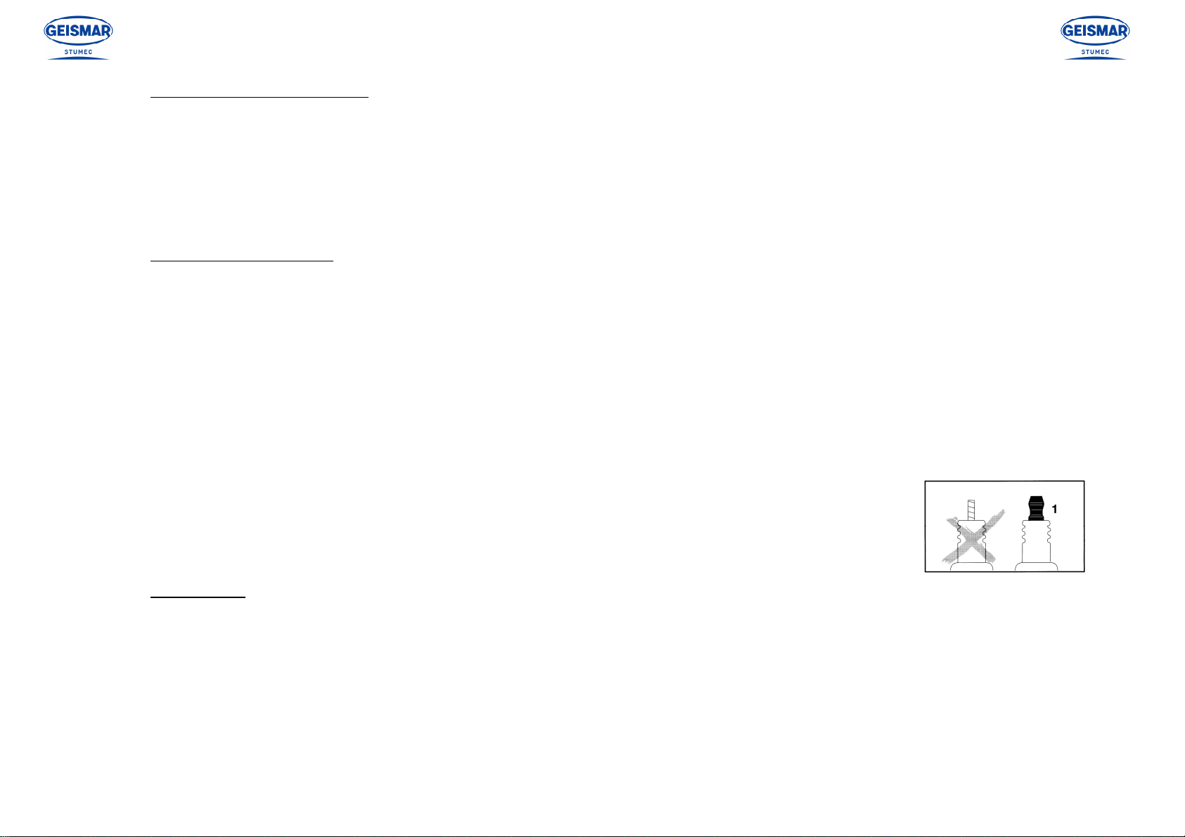
Carefully tighten the fuel filler cap each time, and check that no fuel leaks from it.
Always remove a filler cap slowly, to enable any internal pressure to be released without spraying any fuel out. Take special care if the surrounding
temperature is high.
When putting fuel in a machine that has heated up, never fill the tank completely. Do not put in more than three-quarters of the tank capacity.
If fuel starts to boil in the tank when putting fuel in a machine that has heated up, screw the cap on again immediately and leave the machine to cool
down.
Make sure the fuel used is suitable for the type of engine on the machine. See the user manual for the engine.
Do not inhale fuel vapour.
If it is necessary to drain the fuel tank, pour the fuel into a container designed for the purpose and bearing the labels required by regulations. Always
close them tightly, even if they only contain a small quantity. Never use a glass container.
Never use fuel for cleaning work. Use only non-flammable, non-toxic products that are harmless for the user, the equipment and environment.
If fuel has been spilt near the filling area for any reason, clean it up immediately. Clean straightaway any spillage of fuel on the skin. Make sure no
fuel has been spilt on your clothes; otherwise, change clothes immediately. Remove all rags or other materials used to wipe fuel, and store them in a
safe place well away from all sources of heat or combustion. Move the machine well clear of any spilt fuel before starting it up (at least 6 metres
away), and do not move any closer to the area while the engine is running.
I
N CERTAIN CASES HANDLING OIL CAN GIVE RISE TO THE SAME TYPE OF RISKS AS HANDLING FUEL
.
I
T IS THEN ESSENTIAL TO TAKE THE
SAME PRECAUTIONS WITH OIL AS THOSE SET OUT ABOVE FOR FUEL
.

1.3 SECT_Gb_00007_120724.doc 1.3
•Tools to be used on the machine
Use only the types of tools intended for normal use of the machine.
Measure the speed of all rotating tools at regular intervals.
Never use tools at speeds greater than the maximum speed for which they have been designed and approved.
Never use damaged tools or tools that have reached their maximum level of wear.
•The engine on the machine
Never touch the hot parts of the engine, and especially the exhaust pipe. If it is necessary to work on the engine, wait until it has cooled down.
The factory setting of engine corresponds to the conditions of the production site (fuel, temperature, altitude, etc...), verify at receipt of the
machine the rotational speed of the engine and correct if necessary.
Check the engine rotation speed at regular intervals, and especially after fitting tools or reassembling the machine. Adjust if necessary.
Never exceed the speed shown in the technical specifications.
After starting with the choke, remember to return the choke to the normal running position.
Never wind the starter rope around your hand, and never release it suddenly.
If the machine does not operate correctly after the engine has been started, stop the engine and inform the head of maintenance.
For petrol engines, use only spark plugs whose tops are as shown in drawing 1 opposite. If the plug is fitted with a
screw top, make sure the top is fully tightened. After fitting the spark plug, make sure that the plug cap is in good
condition and that it stays firmly on the plug. Carefully check the fastening system to make sure that no sparks can
be formed.
•Using trolleys (If applicable)
A machine designed to work on a trolley must not be used without the trolley. The trolley is thus an integral part of the machine. The machine
and the trolley must not be used separately.
Trolleys whose use is dedicated to a machine must never be used to transport equipment or personnel, or attached to a vehicle.
Before fitting the machine on its trolley, it must be placed correctly on the track to ensure that it can run freely. If it is on a sloping section of
track, make sure the trolley is kept immobile while the machine is being put on the track or taken off it.
Attention, the trolley takes up the full width of the track and can cause injuries to the legs if it hits someone.

1.4 MP12_Gb_00542_090701.doc 1.4
1.4 Specific safety recommendations
1.4.1 Risks that may arise through use of the "MP.12"-type grinder
The main risks for the user and those around that arise when using the "MP.12"-type rail grinder are:
Fire connected with fuel handling.
Fire caused by the sparks coming into contact with inflammable material.
The grinder bursting under abnormal conditions.
Injury caused by sparks (the eyes in particular must be protected) or debris scattered by the grinder.
Severe burns and injuries from contact of part of the body with the grinder, if it is rotating.
Inhalation of particles scattered by the grinder (be sure to wear protective equipment to prevent this)
IMPORTANT
Because the engine can be tilted when in use, the following rules must be respected:
Always keep the grinder in an upright position, stop grinding and stop the engine before removing the cap of the fuel tank.
Never fill the fuel tank more than ¾ full (to avoid spillage when the engine is tilted).
Nnever work on a fuel tank, or handle fuel for any reason, including filling the tank up, in an area where there may be: A source of fire (for example:
lit cigarette, welding torch, sparks, etc.) or very hot materials (for example: welding fragments, cinders, etc.) Always work outside in a well-ventilated
location.
Make sure the fuel tank cap is properly in place and no fuel is leaking.
Refer to §1.2 “Safety and general usage recommendations” and §1.3 “General safety instructions”

1.4 MP12_Gb_01591_160222.doc 1.4
1.4.2 Safety rules to be observed before and during use of the "MP.12"-type grinder
All personnel using this equipment must wear the clothing listed in paragraph §1.3 "General safety instructions / The operator and his environment"
masks or goggles, helmet, smock, fire-proof gaiters or boots.
Use of protection to avoid inhaling the grinding dust is also recommended.
Do not use grind ing wheels that are damaged or have cracks or splits.
For all new or re-assembled grinding wheels, run the engine freely for 30 seconds with all personnel at a distance
(apart from the operator, who must stay at the controls outside of the grinding wheel’s path of rotation, ready to stop the engine if necessary).
When grinding, do not stand in front of the grinding sparks. If necessary, position a screen to block the front jet of sparks to prevent them from reaching
hazardous areas (risk of brush fire in summer).
Do not strike the grinding wheel while it is in use: this may cause it to burst apart.
Make sure the grinding wheel never comes into contact with a sleeper or ballast, or any other foreign body.
Before starting the machine, make sure it is in good condition and the protective hood of the grinding wheel is properly attached. Never modify the
machine.
Install a new hood each time the grinding wheel bursts, and each time there appears to be less resistance.
Regularly measure the rotation speed of the grinding wheel and the engine, in particular after reassembling the machine, and correct it if necessary.
Only use authorised grinding wheels , for both the dimesnsions and the composition.
Never use grinding wheels at speeds greater than the maximum speed recommended by the manufacturer, which must be marked on each grinding wheel.
Before taking the machine off the tracks, or between two series of grinding that require movement, stop the engine and raise the grinding wheel so that it is
hidden inside the protective covering.
ONLY USE GRINDERS
:
Of which the maximum rated speed is higher than the maximum running speed of the grinder holding shaft,
which is marked on the machine.
Of which the outside diameter is less than or equal to the maximum authorized diameter,
which is marked on the machine.
Autorized by the regulation in application for this type of machine
IN ORDER NOT TO DAMMAGE THE ENGINE :
- Do NOT tilt the grinder more than 10° from the vertical, opposite side of the
operator. When the machine is tilted excessively and the crutch touches the
ground, the engine stops
- Check that the oil pressure does not exceed 1,5 bar or 22 Psi

1.4 MP12_Gb_00548_090701.doc 1.4
1.4.3 Personal protective equipment
•All personnel using this equipment must wear the clothing listed in paragraph §1.3 "General safety instructions / The operator and his environment". They
must also wear anti-spark protection, such as: mask or goggles, smock and non-slip sturdy gloves, fire-resistant gaiters or boots.
•They must wear a helmet and safety boots with non-slip soles and steel toes.
•Use of protection to avoid inhaling the grinding dust is also recommended.
•Use of hearing protection is also recommended. Nonetheless, refer to the applicable rail regulations governing the work site to determine if
this can be used or not.
•In addition to the use of the Personal Protective Equipment described in §1.3 "General safety instructions / The operator and his environment", we
recommend use of hearing protection. Nonetheless, refer to the applicable rail regulations governing the work site to determine if this can be used or not.

1.4 MP12_Fr_01592_160222 1.4
1.4.4 Safety symbols and recommendations
The safety pictograms and recommendations must be present on the grinder at the indicated location.
If one of them is missing or has deteriorated, another must be ordered immediately and installed in its place.
If a component bearing a label has been replaced, make sure a new label is placed on the replacement part.
Reference: N°
12412
Location: Riveted to the machine chassis above
the grinding wheel housing.
(for the direction of this plate, refer to §3.1
“Installing the grinding wheel”).
Reference: N°
12670
Location: Riveted to the machine chassis above
the grinding wheel housing.
(for the direction of this plate, refer to §3.1
“Installing the grinding wheel”).
Reference: N° 54079 (red background)
Location: Stuck on the engine tank next to the
filling cap.
Reference: N° 12528 (yellow background)
Location: Stuck on the machine chassis next to the
lock handle of the operating lever.
Reference: N° 12517K (yellow background)
Location: Stuck on the engine air filter.
Reference: N° HZM (blue background)
Location: Stuck on the engine air filter.
Reference: N° 37654 (white background)
Location: Stuck on the engine tank next to the filling cap.
Référence : N°
37674
Emplacement : Riveted to
the fuel tank
Référence : N°
37677
Emplacement : Riveted to
the fuel tank

2.1 MP12_Gb_00554_090701.doc 2.1
CHAPTER 2 – DESCRIPTION OF THE MACHINE
2.1 General points
Manufacturer:
S
OCIETE
TU
RRIPINOISE DE
MEC
ANIQUE
Route d’Italie
38110 LA TOUR DU PIN
FRANCE
Description of equipment:Section grinder
Type MP.12
The MP.12 section grinder is designed for grinding railheads and welds, including the curves and sides.
Its exceptional performance and durability, due to its rigid and non-deformable alloy chassis, provide the operator with optimum ease of use.
The guiding rollers and broad wheelbase guarantee consistency of grinding from the horizontal to the vertical.
It was entirely designed using the most modern techniques used in the domain of machine tooling.

2.2 MP12_Fr_01593_160222 2.2
2.2 Overview
Ref. Description
A Manoeuvring handle
B Grinding wheel adjusting
assembly
C Engine shutdown
D Engine
E Carrying handle (x2)
F Guide roller
G Grinding wheel housing
H Stop lug
J Manoeuvring lever lock handle
K Grinding wheel descent
blocking handle
L Crutch anti tilt
Engine cut
M Hour meter
N Engine pressure gauge
Do not exceed 1.5 bar
O Fuel tank
To simplify machine identification, when ordering spare parts, please specify their type and number,
engraved on the nameplate.
D
E
J
G
A
B
K
E
L
F
F
F
M
C
N
O

2.3 MP12_Gb_01594_160222.doc 2.3
2.3 Technical characteristics
ENGINE TYPE
MP.12 Engine Robin DY27-2D
Machine dimensions
Length / width / height
mm
---/---/---
Masses
Machine (no load)
kg
---
Machine (in working order)
kg
---
Noise
Acoustic pressure level (La
eq
) (1)
dB (A)
--- (±2)
Acoustic power level (Lwa) (2
dB (A)
--- (±2)
Vibrations
Level of vibration (Aeq) (3)
ms -2
--- (±2%)
Engine
Power
kW
5 (= 3,7ch) à 3600 tr/min
Fuel tank capacity
litre
3,2
Fuel consumption
……
Gasoil
Number of cycles per tank
……
Starting
..….
Automatic return starting cable
Machine
Engine adjustment speed (max speed)
tr/min
3600
Grinding wheel rotation speed
tr/min
3600
Max grinding wheel diameter
mm
150
Maximum cant for which the machine is stable
mm
---
Grinding wheel
Outside diameter
mm
150
Inside diameter
mm
55
Height
mm
72
Authorised grinding wheel rotation speed
tr/min
6370
Authorised wheel peripheral speed.
m/sec
50
Composition of the grinding wheel
……
Meule résinoïde (meule constituée d’agglomérants synthétiques)
Grinding wheel travel height
mm
62
(1) Measurements done according to NF EN ISO 11204 while machine working. (2) Measurements done according to NF EN ISO 3746 while machine working. (3) Measurements done according to NF EN ISO 5349 while machine working.

2.5 MP12_Fr_01596_160222 2.5
2.5 Machine location inside the clearance gauge
The diagram below shows the dimensions of the machine as compared with the lower UIC 505-1 clearance gauge
(track with a nominal gauge of 1.435 m).
9800 mm
9450 mm
1220 mm

3.1 MP12_Gb_00572_090701.doc 3.1
CHAPTER 3 – INSTALLATION – STARTING
3.1 Installing the grinding wheel
The grinding wheel must be installed with the engine off and the machine on the ground.
To install the grinding wheel, proceed as follows:
Disassembling the grinding wheel:
1 →Lower the grinding wheel as far as possible, then remove the grinding wheel housing ②by removing the 2 bolts ①(17 spanner) (see fig.1).
2 →Immobilise the pin ④using a 27 open-ended spanner then unscrew the “grinding wheel+wheel holder” assembly using a second 27 open-ended spanner.
3 →Separate the grinding wheel ⑥from the grinding wheel holder plate ⑤:
- assembly Fig.2 >> Unscrew the fastening bolts ③(13 open-ended spanner).
- assembly Fig.3 >> Immobilise the grinding wheel ⑥, then unscrew the wheel holder plate ⑤(27 open-ended spanner).
Assembling the grinding wheel:
5 →- assembly Fig.2 >> Position the grinding wheel ⑥so the inside Ø is on the sholder of the wheel holder plate ⑤. Place the fastening bolts ③on the
grinding wheel ⑥and bring them together until they touch. Tighten them.
- assembly Fig.3 >> Immobilise the grinding wheel ⑥, then screw in the wheel holder plate ⑤(27 open-ended spanner).
6 →To put the “grinding wheel +wheel holder” assembly back, carry out operations 2 and 1 in the opposite order from disassembly.
The grinding wheels have expiry dates. Make sure these have not been exceeded.
4
4
Fig.2 Fig.3
6
3
5
5
6
1
2
Fig.1
T
HE GRINDSTONES YOU USE SHOULD MEET THE TECHNICAL SPECIFICATIONS STATED IN
§
2.3
"T
ECHNICAL
DATA
/
G
RINDSTONE
"

3.2 MP12_Gb_00575_090701.doc 3.2
3.2 Placing the machine on the track
At least two people must be involved when placing the machine on or taking it off track. Nonetheless, if the work area is difficult to access, more people may
be required to ensure safe handling operations.
•To place the machine on the track, proceed as follows:
Take the machine by the carrying handles ① on either side of the machine. Position the machine on the track. The rollers ②and ③must roll freely on the
rails. If the machine is equipped with a balancing bar (optional), attach it so the roller rolls freely on the rail.
If the machine is equipped with a balancing bar, it must be immobilised (with support) once on the track, to avoid moving and injuring someone in case of
a collision.
THE ENGINE MUST BE OFF WHEN THE MACHINE IS PLACED ON OR TAKEN OFF THE TRACK.
1
1
2
3
3

3.3 MP12_Gb_00576_090701.doc 3.3
3.3 Guide roller settings
The guide roller separation is adjustable, so the machine can be placed on all types of rail, regardless
of the width of the railhead.
3.3.1 Settings for flat-bottomed rails
Adjust one of the two guide rollers, as follows:
•Remove the two guide flanges ①held in place by nuts and locknuts ①(25 hook spanner).
•Remove or replace, for each of the two roller axes, the necessary number of spreaders ③
(the same on both sides) for clearance of 5 to 10mm between the railhead and one of the two
guide flanges ①(see diagram)
•Place the unused spreaders outside the guide flanges ①.
•Replace and securely block the nuts and locknuts ②.
Mount the second guide roller in the same way.
3.3.2 Settings for grooved rails (if equipped)
Adjust one of the two guide rollers, as follows:
•Unblock the nuts ②and ③.
•Position the machine on the rail, placing the guide rollers ④and ⑤in the groove.
•Position the grinding wheel ⑥level with the outside of the rail (see diagram), progressively
moving the machine towards the outside of the track.
•Bring the guide roller ④into contact with the outside of the groove and block the nuts ③.
•Push the shaft ①to bring the guide roller ⑤to within a few millimetres of the inside of the
groove, and block the nut ②.
We recommend using an Ø80 mm grinding wheel and an adapted grinding wheel protective hood
(Ref. 37101) that lets you raise the fillet.
2
3
1
5 to 10mm
1
2
3
6
4
5
2 to
4m
m

3.4 MP12_Fr_01598_160222 3.4
3.4 Fuel
- The rail grinder’s engine must use of Gas-oil
- Motor oil use 4-stroke motor oil that meets or exceeds the engine recommendations.
- Storing the Gas-oil Empty the fuel tank and run the engine until it stops after each use of the machine. Filling up with fuel
Be careful when opening the fuel can.
The can may be under pressure. Open it carefully.
Before filling up, carefully clean the plug and the area around it so no impurity enters the tank.
Position the machine vertically, so the tank plug is pointing up.
•Opening the plug:
➊ Turn the plug counter-clockwise by hand as far as possible.
➋ Remove the tank plug.
Carefully open the fuel tank plug so that any excess internal pressure can escape slowly, without ejecting fuel.
Never open the plug using a tool. This risks damaging the plug and fuel may escape.
•Fill the tank in a well-ventilated area and never near possible sources of fire, such as: blow torches, sparks, soldering equipment.
•Move the machine at least 6m from where it was filled up before starting it.
•Closing the plug:
➊Position the tank plug in front of the filling hole.
➋ Turner the plug clockwise as far as possible.
NEVER FILL THE
FUEL TANK WITH
THE ENGINE
RUNNING OR
EXCESSIVELY HOT
When filling, do not spill the fuel and never completely fill the tank. Never completely fill the tank, but
only put in a quantity of fuel equal to ¾ of the maximum capacity.
Table of contents
Other GEISMAR STUMEC Grinder manuals
Popular Grinder manuals by other brands

Flex
Flex LE 9-11 125 Original operating instructions

Parkside
Parkside PWS 230 SE Operation and safety notes

Abbot & Ashby
Abbot & Ashby ATBG600/8 manual

Hitachi
Hitachi G 12SE2 Handling instructions

Flex
Flex LD 18-7 125 R operating instructions

Parkside
Parkside PDOS 200 B2 Translation of the original instructions