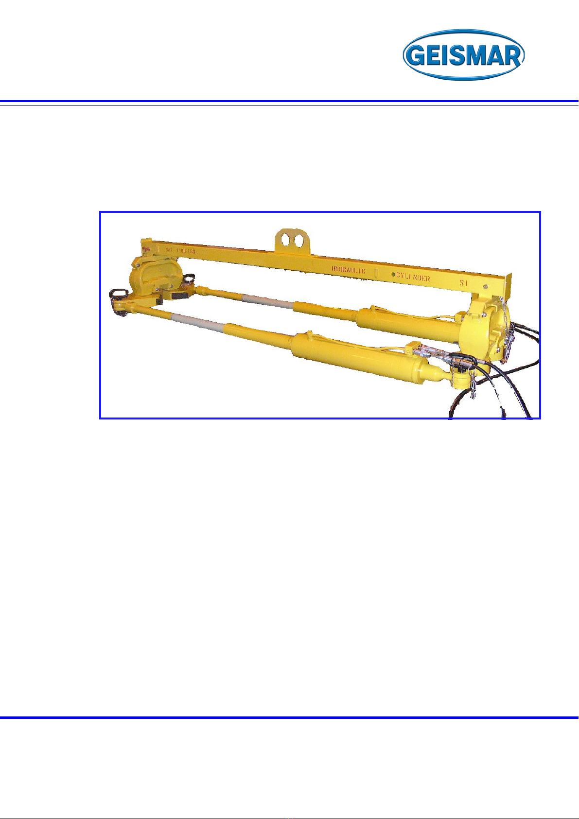
HYDRAULIC RAIL TENSOR
H77646_1017
TYPE
TH 70 STP
SUMMARY
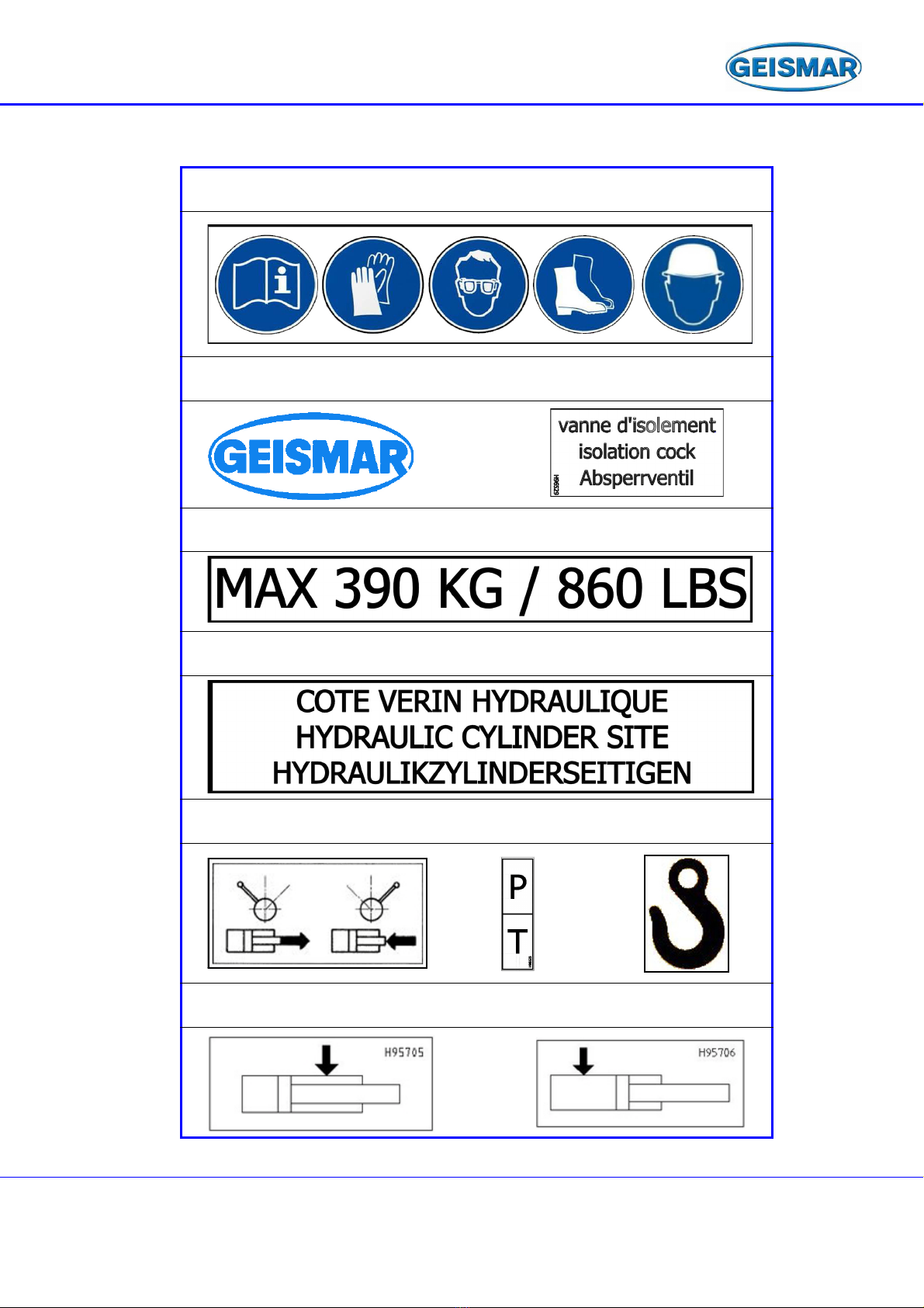
TENSOR MARKING ....................................................................................................................................................................... 5
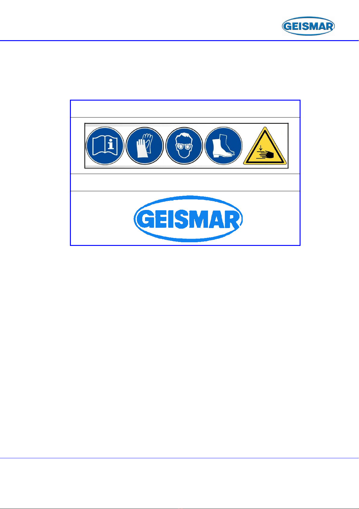
LIFTING BEAM MARKING ............................................................................................................................................................. 7
WARNINGS .................................................................................................................................................................................... 9
CHAPTER - 1 SAFETY
1 – 1 FOREWORD......................................................................................................................................................................... 11
1 – 2 WARNING............................................................................................................................................................................. 11
1 – 3 GENERAL SAFETY REGULATIONS ................................................................................................................................... 12
CHAPTER - 2 DESCRIPTION
2 – 1 GENERAL PRESENTATION................................................................................................................................................ 15
2 – 2 GENERAL............................................................................................................................................................................. 16
2 – 3 OPERATING CONDITIONS ................................................................................................................................................. 16
CHAPTER - 3 TECHNICAL CHARACTERISTICS
3 – 1 GENERAL CHARACTERISTICS.......................................................................................................................................... 17
3 – 2 OVERALL SIZE..................................................................................................................................................................... 18
CHAPTER - 4 TENSOR EQUIPMENT
4 – 1 LOCATION OF THE MAIN UNITS........................................................................................................................................ 19
CHAPTER - 5 OPERATING INSTRUCTIONS
5 – 1 HANDLING INSTRUCTIONS................................................................................................................................................ 21
5 – 2 INSTALLING THE TENSOR................................................................................................................................................. 21
5 – 2 – 1 INSTALLING THE TENSOR IN TRACTION MODE................................................................................................................. 21
5 – 2 – 2 INSTALLING THE TENSOR IN THRUST MODE.................................................................................................................... 21
5 – 3 CONNECTING TO THE ENERGY UNIT .............................................................................................................................. 22
5 – 4 RAILWAY ENVIRONMENT .................................................................................................................................................. 22
CHAPTER - 6 MAINTENANCE
6 – 1 GENERAL MAINTENANCE INSTRUCTIONS...................................................................................................................... 23
6 – 1 – 1 RULES TO BE FOLLOWED ............................................................................................................................................. 23
6 – 2 CONTROLS .......................................................................................................................................................................... 23
6 – 2 – 1 FLEXIBLE HOSES.......................................................................................................................................................... 23
6 – 2 – 2 STIRRUPS ................................................................................................................................................................... 23
6 – 3 MAINTENANCE.................................................................................................................................................................... 24
6 – 3 – 1 CONTROLS .................................................................................................................................................................. 24
6 – 3 – 2 CLEANING ................................................................................................................................................................... 24
6 – 3 – 3 GREASING................................................................................................................................................................... 24
6 – 3 – 4 TABLE OF EQUIVALENCES FOR GREASES....................................................................................................................... 25
6 – 3 – 5 HYDRAULIC OIL............................................................................................................................................................ 25
6 – 3 – 6 TABLE OF EQUIVALENCES FOR HYDRAULIC OILS ............................................................................................................ 25