Version
03/11
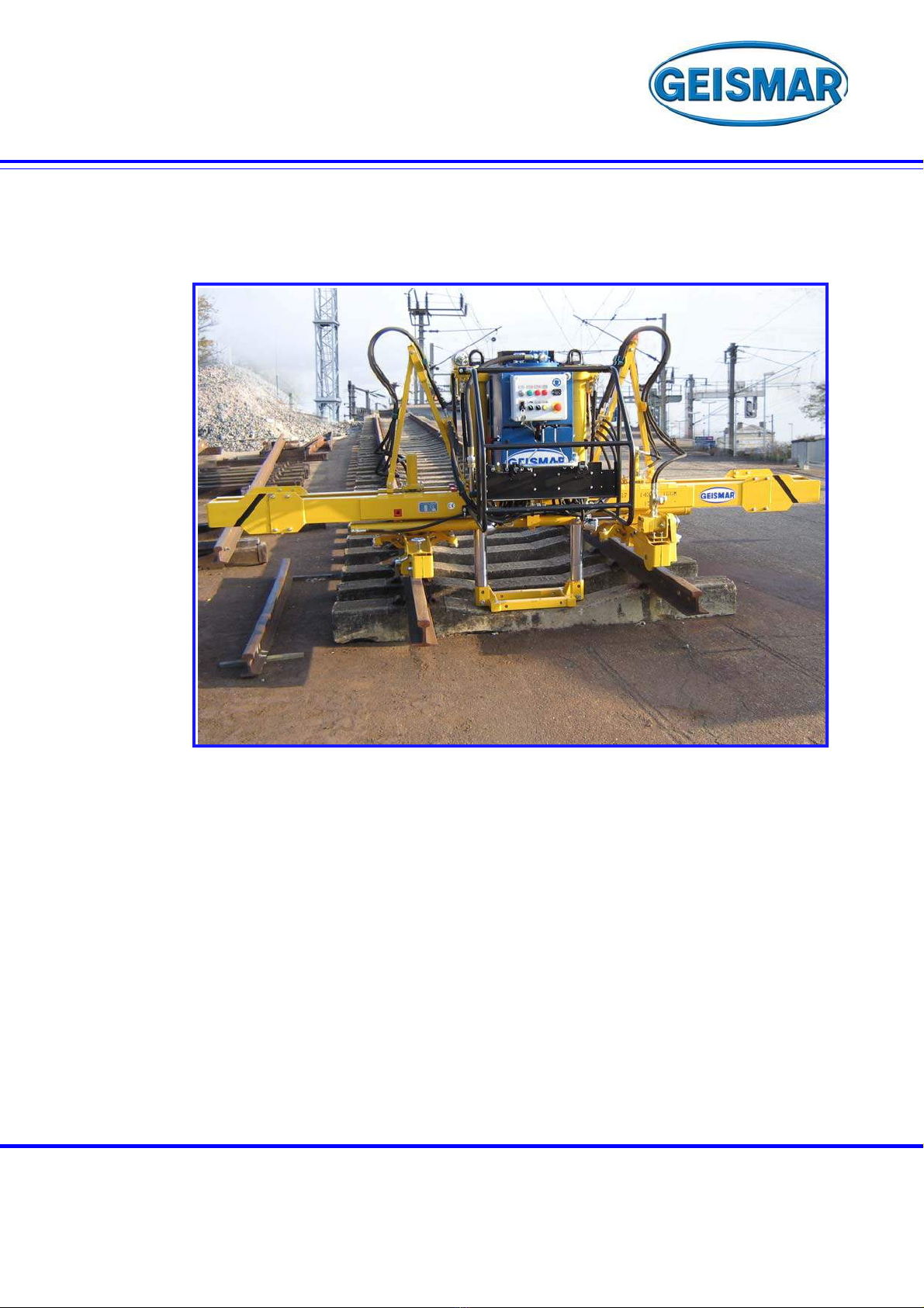
HYDRAULIC RAIL THREADER
H90461 / NO 10055
TYPE MPR – M
SUMMARY
CHAPTER - 1 SAFETY
1 – 1 FOREWORD .........................................................................................................................................................1
1 – 2 WARNING .............................................................................................................................................................2
1 – 3 GENERAL SAFETY INSTRUCTIONS...................................................................................................................2
1 – 3 – 1 T
RANSPORT
– S
TORAGE
................................................................................................................................................ 3
1 – 4 SPECIAL SAFETY INSTRUCTIONS.....................................................................................................................4
1 – 4 – 1 E
QUIPMENT
WITH
A
COMBUSTION
ENGINE
....................................................................................................................... 4
1 – 4 – 2 E
QUIPMENT
WITH
ELECTRICAL
DEVICES
.......................................................................................................................... 4
1 – 4 – 3 E
QUIPMENT
WITH
HYDRAULIC
DEVICES
........................................................................................................................... 4
1 – 4 – 4 L
IFTING
EQUIPMENT
....................................................................................................................................................... 5
CHAPTER - 2 PRESENTATION
2 – 1 GENERAL PRESENTATION.................................................................................................................................7
2 – 2 GENERAL INFORMATION ...................................................................................................................................8
CHAPTER - 3 TECHNICAL CHARACTERISTICS
3 – 1 GENERAL CHARACTERISTICS...........................................................................................................................9
3 – 2 DIMENSIONS OF THE RAIL THREADER..........................................................................................................11
3 – 3 LOCATION IN LOADING CLEARANCE..............................................................................................................12
CHAPTER - 4 EQUIPMENTS
4 – 1 LOCATION OF THE MAIN UNITS ......................................................................................................................13
4 – 2 HYDRAULIC UNIT...............................................................................................................................................14
4 – 4 HYDRAULIC CONTROLS...................................................................................................................................15
4 – 5 MOTORISED TROLLEYS ...................................................................................................................................16
4 – 5 – 1 T
RAVEL
TROLLEY
......................................................................................................................................................... 17
4 – 6 MAIN FRAME ......................................................................................................................................................19
4 – 7 ELETRICAL UNIT................................................................................................................................................21
4 – 7 – 1 E
LECTRICAL
ENCLOSURE
............................................................................................................................................. 21
4 – 7 – 2 B
ATTERY
COMPARTMENT
............................................................................................................................................. 22
4 – 7 – 3 L
INING
T
RACK
............................................................................................................................................................. 23
CHAPTER - 5 OPERATING INSTRUCTIONS
5 – 1 HANDLING INSTRUCTIONS ..............................................................................................................................25
5 – 2 PREAMBLE .........................................................................................................................................................25
5 – 2 – 1 R
EMINDER
OF
TERMS
USED
IN
THIS
CHAPTER
............................................................................................................... 25