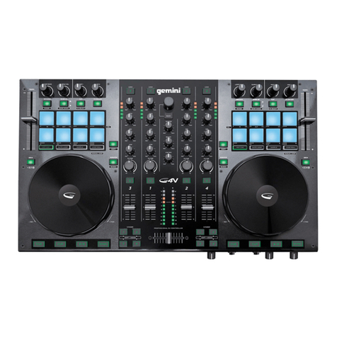
Gemini PMX-20 User manual

At Gemini, our highest priority is making your experience unforgettable.
Need help with setting up, troubleshooting, or looking for some tips?
We’re here for you, Monday through Friday 9AM-5PM EST.
PMX-20
DIGITAL PERFORMANCE MIXER
USER MANUAL

2PMX-20
DIGITAL PERFORMANCE MIXER
SAFETY INSTRUCTIONS
1. Read these Instructions.
2. Keep these Instructions.
3. Heed all Warnings.
4. Follow all Instructions.
5. Do not use this apparatus near water.
6. Clean only with dry cloth.
7. Do not block any ventilation openings.
Install in accordance with the manufacturer’s
instructions.
8. Do not install near any heat sources such
as radiators, heat registers, stoves, or other
apparatus (including amplifi ers) that produce
heat.
9. Do not defeat the safety purpose of the
polarized plug. A polarized plug has two
blades with one wider than the other. The
wide blade is provided for your safety. If the
provided plug does not fi t into your outlet,
consult an electrician for replacement of the
obsolete outlet.
10. Protect the power cord from being
walked on or pinched, particularly at plugs,
convenience receptacles, and the point where
they exit from the apparatus.
11. Only use attachments/accessories
specifi ed by the manufacturer.
12. Use only with the cart, stand, tripod,
bracket, or table specifi ed by the
manufacturer or sold with the apparatus.
When a cart is used, use caution when
moving the cart/apparatus combination to
avoid injury from tip-over.
13. Unplug this apparatus during lightning
storms or when unused for long periods of time.
14. Refer all servicing to qualifi ed service
personnel. Servicing is required when
the apparatus has been damaged in any
way, such as power-supply cord or plug is
damaged, liquid has been spilled or objects
have fallen into the apparatus, the apparatus
has been exposed to rain or moisture, does
not operate normally, or has been dropped.
15. WARNING: To reduce the risk of fi re or
electric shock, do not expose this apparatus
to rain or moisture.
16. Since the device’s power cable is used as the
primary disconnection device, the power cable
should remain readily operable at all times.
17. The ventilation should not be impeded by
covering the ventilation openings with items,
such as newspapers, table-cloths, curtains, etc.
18. No naked fl ame sources, such as lighted
candles, should be placed on the apparatus.
19. The apparatus should be used in moderate
climate.
20. The apparatus shall not be exposed to
dripping or splashing and no objects fi lled
with liquids (such as drinks) shall be placed
on the apparatus.
WARNING
To reduce the risk of electric shock, do not
remove cover (or back). There are no user
serviceable parts inside. Maintenance and
repairs should be exclusively carried out by
qualifi ed service personnel.
CAUTION
To reduce the risk of electric shock, do not re-
move cover. No user serviceable parts inside.
Refer servicing to qualifi ed service personnel
only.
The warning triangle with exclamation
mark indicates important operating and
maintenance instructions.
The warning triangle with lightning
symbol indicates dangerous
uninsulated voltage inside the unit,
which may cause an electrical shock.
To prevent electric shock, do not use this
Polarized Plug with an extension cord,
receptacle or other outlet unless the blades
can be fully insert to prevent blade exposure.

3
PMX-20
DIGITAL PERFORMANCE MIXER
INDEX
ENGLISH //
CONTENTS
FUNCTION
DESCRIPTION
CONNECTION DIAGRAM
COMPUTER CONNECTION
OPERATIONAL MODES
USING THE FX LOOP
CROSSFADER CURVE CONTROL
CROSSFADER REPLACEMENT
TROUBLESHOOTING
MIDI SPECIFICATION
AUDIO SPECIFICATION
RGB COLOR CHART (MIDI)
WARRANTY AND REPAIR
LIMITED WARRANTY
RETURN/REPAIR
ESPAÑOL //
CONTENIDO
FUNCIÓN
DESCRIPCIÓN
DIAGRAMA DE CONEXIÓN
CONEXIÓN DE LA COMPUTADORA
MODOS OPERACIONALES
USANDO EL LOOP FX
CONTROL CURVA CROSSFADER
REEMPLAZO DEL CROSSFADER
SOLUCIÓN DE PROBLEMAS
ESPECIFICACIÓN MIDI
ESPECIFICACIÓN DE AUDIO
TABLA DE COLORES RGB (MIDI)
FRANÇAIS //
CONTENU
FONCTION
LA DESCRIPTION
DIAGRAMME DE CONNEXION
RACCORDEMENT INFORMATIQUE
MODES OPÉRATIONNELS
UTILISATION DE LA BOUCLE D’EFFETS
CROSSFADER CURVE CONTROL
REMPLACEMENT DU CROSSFADER
DÉPANNAGE
SPÉCIFICATION MIDI
SPÉCIFICATION AUDIO
TABLEAU DES COULEURS RGB (MIDI)
DEUTSCHE //
INHALT
FUNKTION
BESCHREIBUNG
SCHALTPLAN
COMPUTERVERBINDUNG
BETRIEBSMODI
VERWENDUNG DER FX-LOOP
CROSSFADER-KURVENKONTROLLE
CROSSFADER ERSATZ
FEHLERBEHEBUNG
MIDI-SPEZIFIKATION
AUDIO-SPEZIFIKATION
RGB-FARBTABELLE (MIDI)
ITALIANO //
CONTENUTO
FUNZIONE
DESCRIZIONE
SCHEMA DI COLLEGAMENTO
CONNESSIONE DEL COMPUTER
MODI OPERATIVI
UTILIZZO DEL LOOP FX
CONTROLLO DELLA CURVA DI CROSSFADER
SOSTITUZIONE DEL CROSSFADER
RISOLUZIONE DEI PROBLEMI
SPECIFICAZIONE MIDI
SPECIFICAZIONE AUDIO
TABELLA DEI COLORI RGB (MIDI)
3
4
6
6
6
6
6
6
7
7
8
9
9
36
36
36
3
10
12
12
12
12
12
12
13
13
14
15
15
3
16
18
18
18
18
18
18
19
19
20
21
21
3
22
24
24
24
24
24
24
25
25
26
27
27
3
28
30
30
30
30
30
30
31
31
32
33
33
CONTENTS ENGLISH //
Please ensure that you fi nd these accessories
included with your PMX-20 Digital Performance
Mixer with USB audio interface:
(1) PMX-20 Digital Mixer
(1) Power Cord
(1) USB Cable (to connect to a computer)
(1) Instruction Manual
CONTENIDO ESPAÑOL //
Asegúrese de encontrar estos accesorios
incluidos con su mezclador de rendimiento
digital PMX-20 con interfaz de audio USB:
(1) Mezclador digital PMX-20
(1) Cable de alimentación
(1) Cable USB (para conectarse a una
computadora)
(1) Manual de instrucciones
CONTENU FRANÇAIS //
Veuillez vous assurer que vous trouvez ces
accessoires inclus avec votre console de mixage
numérique PMX-20 avec interface audio USB:
(1) Mélangeur numérique PMX-20
(1) Cordon d’alimentation
(1) Câble USB (pour se connecter à un
ordinateur)
(1) Manuel d’instructions
INHALT DEUTSCHE //
Bitte stellen Sie sicher, dass Sie dieses
Zubehörteil im Lieferumfang Ihres digitalen PMX-
20-Mischpults mit USB-Audio-Interface fi nden:
(1) PMX-20 Digitalmischer
(1) Netzkabel
(1) USB-Kabel (zum Verbinden mit einem
Computer)
(1) Bedienungsanleitung
CONTENUTI ITALIANO //
Assicurati di trovare questi accessori in dotazione
con il tuo Digital Performance Mixer PMX-20 con
interfaccia audio USB:
(1) Mixer digitale PMX-20
(1) Cavo di alimentazione
(1) Cavo USB (per collegarsi a un computer)
(1) Manuale di istruzioni

4PMX-20
DIGITAL PERFORMANCE MIXER
FUNCTION ENGLISH //
TOP VIEW
1. Eff ect 1 Button ON/OFF
Turns Eff ect 1 ON or OFF
2. Eff ect 1 Knob
Controls value of Eff ect 1
3. Eff ect Button 2 ON/OFF
Turns Eff ect 2 ON or OFF
4. Eff ect Knob 2
Controls value of Eff ect 2
5. Loop Size Encoder
Turn to increase or decrease loop size
6. Loop Button ON/OFF
Turns looping for associated deck ON or OFF
7. Hotcues Mode Button
Switches buttons 1-8 to HOTCUE mode
8. Samples Mode Button
Switches buttons 1-8 into SAMPLES mode
9. Hotcue Buttons
Triggers or sets Hotcues
10. USB Button
Switches channel source from external to
USB audio interface
11. Channel Gain Knob
Turn to change input gain of channel
12. High Frequency EQ Knob
Turn to adjust the High EQ value
13. Mid Frequency EQ Knob
Turn to adjust the Mid EQ value
14. Low Frequency EQ Knob
Turn to adjust the Low EQ value
15. Dual Pole (HP/LP) Filter Knob
• Turn to adjust fi lter for selected channel
• Center - No Filter Eff ect
• Clockwise from center – High-pass Filter
• Counter-Clockwise from center – Low-pass
fi lter
16. FX Send Button
Press to send channel audio to eff ects loop
17. CUE/PFL Button
Press to insert channel into Cue (PFL) bus
18. 45mm Channel Fader
Move to increase or decrease volume for
selected channel
19. Channel LED Meter
Shows pre-fader level of selected channel
20. Load Deck 1/3 Buttons
Loads selected track into the Deck 1 or Deck
3 Player
21. Load Deck 2/4 Buttons
Loads selected track into Deck 2 or Deck 4
Player
22. Track Search Encoder
Turn to scroll through library/Press to enter
a directory
23. Back Button
Press to go back one directory
24. Forward Button
Press to go into the highlighted directory
25. Master Volume Knob
Turn to increase Master Output Volume
26. Booth Volume Knob
Turns to increase Booth Output Volume
27. FX Return Knob
Adds FX return signal back to Master Bus
28. Talkover Button
Lowers the volume of the non-microphone
channels
29. Mic On/Off Button
Turns the mic channel on or off
30. Mic Level Knob
Turn to increase volume of attached
Microphone
31. Cue Split Knob
Splits cue between Cue bus and Program bus
32. Cue Level Knob
Turn to increase or decrease volume of Cue
bus
33. Master Bus LED Meter
Shows level of Master bus
34. 45mm Crossfader
Move to select channel audio sent to Master
bus
REAR VIEW
35. Power Button
Turns mixer on or off
36. Master XLR (Balanced) Outputs
Professional-grade stereo outputs
37. Master RCA (Unbalanced) Outputs
Consumer quality Stereo outputs
38. Booth Output
Output for monitoring speakers
39. Record Output
Output for recording devices
40. USB Type-B Connector
To connect PMX-20 to a computer
41. CH4 Line/Phono Switch
Switch to control level of CH4 input
42. CH4 RCA Inputs
Input for CH4 Source
43. CH3 RCA Inputs
Input for CH3 Source
44. CH3 Line/Phono Switch
Switch to control level of CH3 input
45. CH2 Line/Phono Switch
Switch to control level of CH2 input
46. CH2 RCA Inputs
Input for CH2 Source
47. CH1 RCA Inputs
Input for CH1 Source
48. CH1 Line/Phono Switch
Switch to control level of CH1 input
49. Microphone Input Combo Jack
Connect XLR or 1/4” TRS Dynamic
Microphone
50. FX Send Output
RCA Output for FX Send Loop
51. FX Return Input
RCA Input for FX Send Loop
52. IEC 3-Prong Mains Power connector
Mains AC Power connector
53. Ground for use with TT sources
54. Kensington Lock Connection
Connect Kensington Lock to secure mixer

5
PMX-20
DIGITAL PERFORMANCE MIXER
CUE 1CUE 3 CUE 4CUE 2
FX-SENDFX-SEND FX-SENDFX-SEND
SAMPLES
HOTCUES
LOOP ON
SAMPLES
HOTCUES
LOOP ON
ON ON
24
24 ON ON
31
1
FWD
ON-PRE
OFF-POST
BACK
3
USB USB USB USB
ONON
1 3
2 4
5
7
8
10
22
13
25
27
11
23
14
26
28
12
24
15
16
17
18 19
20 21
6
29
32
30
33
31
34
36 37
48
47 49
50 51
52
53 54
38
44
39
43
40
41
42
45
46
TOP VIEW
REAR VIEW
9
35

6PMX-20
DIGITAL PERFORMANCE MIXER
CONNECTION DIAGRAM
COMPUTER CONNECTION
Be sure that the PMX-20 is connected to your
computer via the included USB cable.
(Consult Connection Diagram).
The PMX-20 Mixer is a Class Compliant multi-channel
audio and MIDI interface, with low latency multi-
channel soundcard. In OSX, no additional drivers
are needed. In Windows, to get the best possible
performance we recommend you download and
install the Gemini ASIO drivers from the PMX-20
product page on www.geminisound.com. The PMX-
20 product page is also where you’ll fi nd additional
information and downloads for your PMX-20 mixer
(MIDI confi guration fi les, etc.).
Your PMX-20 mixer is capable of receiving fi rmware
updates via the Gemini Updater software, which is
also available for download from the PMX-20 product
page. It Is a good idea to download and run the
updater software occasionally to verify that you have
the latest version of the device fi rmware. Updates are
provided regularly to fi x problems and add features.
OPERATIONAL MODES
MIXER MODE:The unit operates as a normal mixer
(this is the default mode on power on). No computer
is necessary – all external devices are processed by
the PMX-20’s internal CPU. If connected by USB to an
external computer, it is possible to send and receive
MIDI for nearly all controls and pressing the USB
buttons above each channel will switch that channel
to the internal soundcard instead of the connected
external source.
DVS MODE: User enters this mode by pressing and
holding the USB button on CH1 for about 10 seconds.
Lights will blink indicating a mode change. In this
mode, Channels 1 and 2 are the DVS channels, audio
interface is reconfi gured as a 4 in/4 out interface,
and Channels 3 and 4 work as pure MIDI controls.
Any open DVS software (like Virtual DJ for example)
will be able to recognize and use the onboard audio
interface. However, you may need to purchase the
additional DVS functionality from your software
developer.
FULL MIDI MODE: User enters this mode by pressing
and holding the USB button on CH2 for 10 seconds.
The lights will blink to indicate a mode change. In
this mode, the PMX-20 acts as a pure controller. The
built-in audio interface is reconfi gured as an 8 out
interface (4 stereo outputs). Channel and Master
peak metering is driven by the audio interface.
If you are mapping the PMX-20 into your own
software instead of Virtual DJ, it may be necessary
to set your operational mode BEFORE opening your
software of choice.
USING THE FX LOOP
The FX Loop on the PMX-20 is designed to allow the
use of external hardware eff ects. There is a stereo
send and return.
SEND: Sends are activated with the FX SEND
buttons located above the CUE buttons on each
channel strip. Pressing the FX SEND button sends
the audio from the active channel(s) to the FX SEND
output RCA jacks on the back of the PMX-20. It is
also possible to change the send behavior from
PRE-FADER to POST FADER by using the switch
just below the TRACK SEARCH knob in the middle
channel. PRE-FADER means audio is sent from the
channel after the GAIN knob but before the channel
fader. POST FADER means audio is sent from the
channel after the input GAIN, channel fader, and after
the crossfader.
RETURN: This is how audio from the FX SEND makes
its way back into the mixer. After being processed
by your external eff ect, the processed signal comes
in via the FX RETURN RCA jacks on the back of the
PMX-20. Audio is then mixed into the master audio
bus. In the center channel strip, the RETURN knob
controls the amount of audio added to the master
out.
CROSSFADER CURVE CONTROL
In the bottom right corner
of the PMX-20 is a recessed
knob labeled CURVE
CONTROL. This controls the
response of the crossfader,
allowing anything from a
slow mix to a sharp, fast
transition. To adjust this
parameter, push down on this pot (like a button)
to extend it above the faceplate. Turn the knob
to adjust. Full counterclockwise will produce the
sharpest curve, and full clockwise will produce the
smoothest mix.
HEADPHONES
P
PE
R
CURVE CONTROL
4

7
PMX-20
DIGITAL PERFORMANCE MIXER
2. Remove 12 screws
3. Remove the
faceplate
1. Remove all knob
and fader caps
CROSSFADER REPLACEMENT
To replace the crossfader remove all power
and signal cables from the mixer and, follow
these steps:
1. Remove all knob and fader caps. There
are 38 pieces in all. You do not have to do
anything with the buttons or switches.
2. Remove the 12 faceplate screws using a
small Phillips screwdriver.
3. Remove the faceplate by pulling straight
up. This will expose the sub-chassis and
give you access to the crossfader.
4. The crossfader is connected to the mixer
using a standard molex-style connector.
Use care when separating the connector
from the installed crossfader.
5. If you are installing a crossfader with
adjustable parameters, it makes sense to
make all adjustments needed BEFORE
reinstalling the crossfader and putting the
mixer back together.
(PLEASE NOTE – When replacing the
crossfader, the performance of the crossfader
curve controls may change. Please take a
moment to learn if the behavior of the curve
controls has changed.)
TROUBLESHOOTING
UNIT WILL NOT POWER ON
• Check power cord is securely connected to
mains power and mixer
AUDIO IS DISTORTED (GENERAL)
• Make sure channel GAIN is properly set
• If connected to a computer, verify GAIN and
LEVEL are set correctly in software
• Verify mixer channel and master levels are
not in the red
• Make sure computer resources are not
maxed out (CPU, memory, etc.)
ANALOG SOURCE AUDIO IS DISTORTED
• Make sure correct input level is selected
(LINE or PHONO)
MICROPHONE IS NOT AUDIBLE
• Raise MIC LEVEL until mic is audible.
• Verify connected mic is a dynamic
microphone
AUDIO INTERFACE IS NOT VISIBLE IN
SOFTWARE
• Make sure USB cable is connected to mixer
and computer
• Re-install Gemini ASIO driver
• Make sure PMX-20 audio interface is
selected in software
NO MIDI DEVICES AVAILABLE
• Verify USB cable is connected to mixer and
computer
• Make sure no other application has control
of the MIDI interface
For all other issues, please contact GEMINI support
at 1-844-GEMINI9
4. Access to the
crossfader

8PMX-20
DIGITAL PERFORMANCE MIXER
CONTROL NAME
CH1 Hotcue 8 Button
CH1 Sample 8 Button
CH1 Hotcue 7 Button
CH1 Sample 7 Button
CH1 Hotcue 6 Button
CH1 Sample 6 Button
CH1 Hotcue 5 Button
CH1 Sample 5 Button
CH1 Hotcue 4 Button
CH1 Sample 4 Button
CH1 Hotcue 3 Button
CH1 Sample 3 Button
CH1 Hotcue 2 Button
CH1 Sample 2 Button
CH1 Hotcue 1 Button
CH1 Sample 1 Button
CH1 SAMPLE MODE Button*
CH1 HOTCUE MODE Button*
CH1 Loop On Button
CH1 Loop Size Encoder
CH1 Eff ect 2 Knob
CH1 Eff ect 2 On Button
CH1 Eff ect 1 Knob
CH1 Eff ect 1 Button
CH2 Hotcue 8 Button
CH2 Sample 8 Button
CH2 Hotcue 7 Button
CH2 Sample 7 Button
CH2 Hotcue 6 Button
CH2 Sample 6 Button
CH2 Hotcue 5 Button
CH2 Sample 5 Button
CH2 Hotcue 4 Button
CH2 Sample 4 Button
CH2 Hotcue 3 Button
CH2 Sample 3 Button
CH2 Hotcue 2 Button
CH2 Sample 2 Button
CH2 Hotcue 1 Button
CH2 Sample 1 Button
CH2 SAMPLE MODE Button*
CH2 HOTCUE MODE Button*
CH2 Loop On Button
CH2 Loop Size Encoder
CH2 Eff ect 2 Knob
CH2 Eff ect 2 On Button
CH2 Eff ect 1 Knob
CH2 Eff ect 1 Button
Load CH1 Button
Load CH2 Button
Load CH3 Button
Load CH4 Button
Track Search Encoder (TURN)
Track Search Encoder (PUSH)
Browser Back Button
Browser Fwd Button
Master Volume Knob
Booth Volume Knob
Mic Volume Knob
Cue Split Knob
Cue Volume Knob
Master Out CH1 LED Array
Master Out CH2 LED Array
Crossfader
CH1 LED Array
CH1 Volume Fader
CH1 Cue Button
CH1 Filter Knob
CH1 Low EQ Knob
CH1 Mid EQ Knob
CH1 High EQ Knob
CH1 Gain Knob
CH2 LED Array
CH2 Volume Fader
CH2 Cue Button
CH2 Filter Knob
CH2 Low EQ Knob
CH2 Mid EQ Knob
CH2 High EQ Knob
CH2 Gain Knob
CH3 LED Array
CH3 Volume Fader
CH3 Cue Button
CH3 Filter Knob
CH3 Low EQ Knob
CH3 Mid EQ Knob
CH3 High EQ Knob
CH3 Gain Knob
CH4 LED Array
CH4 Volume Fader
CH4 Cue Button
CH4 Filter Knob
CH4 Low EQ Knob
CH4 Mid EQ Knob
CH4 High EQ Knob
CH4 Gain Knob
CURVE XFADER Knob
TYPE OF DATA
Note
Note
Note
Note
Note
Note
Note
Note
Note
Note
Note
Note
Note
Note
Note
Note
Note
Note
Note
CC (Relative)
CC (Absolute)
Note
CC (Absolute)
Note
Note
Note
Note
Note
Note
Note
Note
Note
Note
Note
Note
Note
Note
Note
Note
Note
Note
Note
Note
CC (Relative)
CC (Absolute)
Note
CC (Absolute)
Note
Note
Note
Note
Note
CC (Relative)
Note
Note
Note
CC (Absolute)
CC (Absolute)
CC (Absolute)
CC (Absolute)
CC (Absolute)
CC (Absolute)
CC (Absolute)
CC (Absolute)
CC (Absolute)
CC (Absolute)
Note
CC (Absolute)
CC (Absolute)
CC (Absolute)
CC (Absolute)
CC (Absolute)
CC (Absolute)
CC (Absolute)
Note
CC (Absolute)
CC (Absolute)
CC (Absolute)
CC (Absolute)
CC (Absolute)
CC (Absolute)
CC (Absolute)
Note
CC (Absolute)
CC (Absolute)
CC (Absolute)
CC (Absolute)
CC (Absolute)
CC (Absolute)
CC (Absolute)
Note
CC (Absolute)
CC (Absolute)
CC (Absolute)
CC (Absolute)
CC (Absolute)
CC (Absolute)
MIDI OUT
on - 90 01 7F/off - 80 01 00
on - 90 09 7F/off - 80 09 00
on - 90 02 7F/off - 80 02 00
on - 90 0A 7F/off - 80 0A 00
on - 90 03 7F/off - 80 03 00
on - 90 0B 7F/off - 80 0B 00
on - 90 04 7F/off - 80 04 00
on - 90 0C 7F/off - 80 0C 00
on - 90 05 7F/off - 80 05 00
on - 90 0D 7F/off - 80 0D 00
on - 90 06 7F/off - 80 06 00
on - 90 0E 7F/off - 80 0E 00
on - 90 07 7F/off - 80 07 00
on - 90 0F 7F/off - 80 0F 00
on - 90 08 7F/off - 80 08 00
on - 90 20 7F/off - 80 20 00
on - 90 21 7F/off - 80 21 00
on - 90 22 7F/off - 80 22 00
on - 90 23 7F/off - 80 23 00
B0 24 **
B0 25 **
on - 90 26 7F/off - 80 26 00
B0 27 **
on - 90 28 7F/off - 80 28 00
on - 91 01 7F/off - 81 01 00
on - 91 09 7F/off - 81 09 00
on - 91 02 7F/off - 81 02 00
on - 91 0A 7F/off - 81 0A 00
on - 91 03 7F/off - 81 03 00
on - 91 0B 7F/off - 81 0B 00
on - 91 04 7F/off - 81 04 00
on - 91 0C 7F/off - 81 0C 00
on - 91 05 7F/off - 81 05 00
on - 91 0D 7F/off - 81 0D 00
on - 91 06 7F/off - 81 06 00
on - 91 0E 7F/off - 81 0E 00
on - 91 07 7F/off - 81 07 00
on - 91 0F 7F/off - 81 0F 00
on - 91 08 7F/off - 81 08 00
on - 91 20 7F/off - 81 20 00
on - 91 21 7F/off - 81 21 00
on - 91 22 7F/off - 81 22 00
on - 91 23 7F/off - 81 23 00
B1 24 **
B1 25 **
on - 91 26 7F/off - 81 26 00
B1 27 **
on - 91 28 7F/off - 81 28 00
on - 94 40 7F/off - 84 40 00
on - 94 41 7F/off - 84 41 00
on - 94 44 7F/off - 84 44 01
on - 94 45 7F/off - 84 45 01
B4 42 **
on - 94 42 7F/off - 84 42 00
on - 94 43 7F/off - 84 43 00
on - 94 46 7F/off - 84 46 00
B4 50 **
B4 51 **
B4 52 **
B4 53 **
B4 54 **
None
None
B4 60 **
None
B0 31 **
on - 90 32 7F/off - 80 32 00
B0 33 **
B0 34 **
B0 35 **
B0 36 **
B0 37 **
None
B1 31 **
on - 91 32 7F/off - 81 32 00
B1 33 **
B1 34 **
B1 35 **
B1 36 **
B1 37 **
None
B2 31 **
on - 92 32 7F/off - 82 32 00
B2 33 **
B2 34 **
B2 35 **
B2 36 **
B2 37 **
None
B3 31 **
on - 93 32 7F/off - 83 32 00
B3 33 **
B3 34 **
B3 35 **
B3 36 **
B3 37 **
B4 72 **
MIDI IN
90 01 **
90 09 **
90 02 **
90 0A **
90 03 **
90 0B **
90 04 **
90 0C **
90 05 **
90 0D **
90 06 **
90 0E **
90 07 **
90 0F **
90 08 **
90 20 **
90 21 **
90 22 **
90 23 **
None
None
90 26 **
None
90 28 **
91 01 **
91 09 **
91 02 **
91 0A **
91 03 **
91 0B **
91 04 **
91 0C **
91 05 **
91 0D **
91 06 **
91 0E **
91 07 **
91 0F **
91 08 **
91 20 **
91 21 **
91 22 **
91 23 **
None
None
91 26 **
None
91 28 **
94 40 **
94 41 **
94 44 **
94 45 **
None
None
94 43 **
94 46 **
None
None
None
None
None
B4 55 **
B4 56 **
None
B0 30 **
None
90 32 **
None
None
None
None
None
B1 30 **
None
91 32 **
None
None
None
None
None
B2 30 **
None
92 32 **
None
None
None
None
None
B3 30 **
None
93 32 **
None
None
None
None
None
None
MIDI SPECIFICATION

9
PMX-20
DIGITAL PERFORMANCE MIXER
CONTROL NAME
CH1 Hotcue 8 Button
CH1 Sample 8 Button
CH1 Hotcue 7 Button
CH1 Sample 7 Button
CH1 Hotcue 6 Button
CH1 Sample 6 Button
CH1 Hotcue 5 Button
CH1 Sample 5 Button
CH1 Hotcue 4 Button
CH1 Sample 4 Button
CH1 Hotcue 3 Button
CH1 Sample 3 Button
CH1 Hotcue 2 Button
CH1 Sample 2 Button
CH1 Hotcue 1 Button
CH1 Sample 1 Button
CH1 SAMPLE MODE Button*
CH1 HOTCUE MODE Button*
CH1 Loop On Button
CH1 Loop Size Encoder
CH1 Eff ect 2 Knob
CH1 Eff ect 2 On Button
CH1 Eff ect 1 Knob
CH1 Eff ect 1 Button
CH2 Hotcue 8 Button
CH2 Sample 8 Button
CH2 Hotcue 7 Button
CH2 Sample 7 Button
CH2 Hotcue 6 Button
CH2 Sample 6 Button
CH2 Hotcue 5 Button
CH2 Sample 5 Button
CH2 Hotcue 4 Button
CH2 Sample 4 Button
CH2 Hotcue 3 Button
CH2 Sample 3 Button
CH2 Hotcue 2 Button
CH2 Sample 2 Button
CH2 Hotcue 1 Button
CH2 Sample 1 Button
CH2 SAMPLE MODE Button*
CH2 HOTCUE MODE Button*
CH2 Loop On Button
CH2 Loop Size Encoder
CH2 Eff ect 2 Knob
CH2 Eff ect 2 On Button
CH2 Eff ect 1 Knob
CH2 Eff ect 1 Button
Load CH1 Button
Load CH2 Button
Load CH3 Button
Load CH4 Button
Track Search Encoder (TURN)
Track Search Encoder (PUSH)
Browser Back Button
Browser Fwd Button
Master Volume Knob
Booth Volume Knob
Mic Volume Knob
Cue Split Knob
Cue Volume Knob
Master Out CH1 LED Array
Master Out CH2 LED Array
Crossfader
CH1 LED Array
CH1 Volume Fader
CH1 Cue Button
CH1 Filter Knob
CH1 Low EQ Knob
CH1 Mid EQ Knob
CH1 High EQ Knob
CH1 Gain Knob
CH2 LED Array
CH2 Volume Fader
CH2 Cue Button
CH2 Filter Knob
CH2 Low EQ Knob
CH2 Mid EQ Knob
CH2 High EQ Knob
CH2 Gain Knob
CH3 LED Array
CH3 Volume Fader
CH3 Cue Button
CH3 Filter Knob
CH3 Low EQ Knob
CH3 Mid EQ Knob
CH3 High EQ Knob
CH3 Gain Knob
CH4 LED Array
CH4 Volume Fader
CH4 Cue Button
CH4 Filter Knob
CH4 Low EQ Knob
CH4 Mid EQ Knob
CH4 High EQ Knob
CH4 Gain Knob
CURVE XFADER Knob
** ADDITIONAL NOTES
See RGB Color Chart for values
00=OFF/01=ON/02=SLOW BLINK/03=FAST BLINK/7F=ON
See RGB Color Chart for values
00=OFF/01=ON/02=SLOW BLINK/03=FAST BLINK/7F=ON
No MIDI Feedback
00=OFF/01=ON/02=SLOW BLINK/03=FAST BLINK/7F=ON
See LED ARRAY FEEDBACK GUIDE
00-7F - All values should be expressed through length of travel
See LED ARRAY FEEDBACK GUIDE
00=OFF/01=ON/02=SLOW BLINK/03=FAST BLINK/7F=ON
See LED ARRAY FEEDBACK GUIDE
00=OFF/01=ON/02=SLOW BLINK/03=FAST BLINK/7F=ON
See LED ARRAY FEEDBACK GUIDE
00=OFF/01=ON/02=SLOW BLINK/03=FAST BLINK/7F=ON
00-7F - All values should be expressed through length of travel
AUDIO SPECIFICATION
INPUTS
Line 150mV, 27 KOhm
Phono 3mV, 47 KOhm
Microphone 1.5mV, 1 KOhm Balanced
OUTPUTS
Max 20V Peak to Peak
Record 225mV, 5 KOhm
GENERAL
Frequency Response 20Hz – 20KHz +/-2dB
Distortion <0.02%
S/N Ratio Better than 85dB
Headphone Impedance 16 Ohm
Power 100-240 VAC 50~60Hz
Specifi cations subject to change without notifi cation
for improvement.
RGB COLOR CHART (MIDI)
VALUE COLOR
00 OFF
01 Solid Green
02 Blinking Green
03 Solid Red
04 Blinking Red
07 Solid Blue
08 Blinking Blue
0B Solid Yellow
0C Blinking Yellow
0F Solid Light Blue
20 Blinking Light Blue
25 Solid Magenta
26 Blinking Magenta
2D Solid White
2E Blinking White

10 PMX-20
DIGITAL PERFORMANCE MIXER
FUNCIÓN ESPAÑOL//
VISTA SUPERIOR
1. Botón de efecto 1 (ON/OFF)
Activa o desactiva el efecto 1
2. Efecto 1 Perilla
Controla el valor del Efecto 1
3. Botón de efecto 2 (ON/OFF)
Activa o desactiva el efecto 2
4. Perilla de efecto 2
Controla el valor del efecto 2
5. Codifi cador de tamaño de bucle
Gire para aumentar o disminuir el tamaño del
bucle
6. Botón ON/OFF del bucle
Activa o desactiva el bucle del deck asociado
7. Botón de modo Hotcues
Cambia los botones 1-8 al modo HOTCUE
8. Botón de modo de muestra
Cambia los botones 1-8 al modo MUESTRAS
9. Hotcue Buttons
Disparadores o sets Hotcues
10. Botón USB
Cambia la fuente del canal de la interfaz de
audio externa a USB
11. Perilla de ganancia de canal
Gire para cambiar la ganancia de entrada del
canal
12. Perilla de ecualización de alta frecuencia
Gire para ajustar el valor de EQ alto
13. Perilla de Ecualización de Media Frecuencia
Gire para ajustar el valor Mid EQ
14. Perilla de ecualización de baja frecuencia
Gire para ajustar el valor de EQ bajo
15. Perilla de fi ltro de doble polo (HP/LP)
• Gire para ajustar el fi ltro para el canal
seleccionado
• Centro - Sin efecto de fi ltro
• En sentido horario desde el centro - Filtro de
paso alto
• En sentido antihorario desde el centro - Filtro
de paso bajo
16. Botón Enviar FX
Presione para enviar audio de canal al bucle
de efectos
17. Botón CUE/PFL
Presione para insertar el canal en el bus Cue
(PFL)
18. Fader de canal de 45mm
Mover para aumentar o disminuir el volumen
para el canal seleccionado
19. Metro LED de canal
Muestra el nivel pre-fader del canal
seleccionado
20. Botones de la plataforma de carga 1/3
Carga la pista seleccionada en el deck 1 o deck
3 player
21. Botones de la plataforma de carga 2/4
Carga la pista seleccionada en Deck 2 o Deck
4 Player
22. Seguimiento de búsqueda de codifi cador
Gire para desplazarse por la biblioteca/
Presione para ingresar un directorio
23. Botón de retroceso
Presione para retroceder un directorio
24. Botón de avance
Presione para ir al directorio resaltado
25. Perilla maestra de volumen
Gire para aumentar el volumen de salida
maestro
26. Perilla de volumen de la cabina
Gira para aumentar el volumen de salida de la
cabina
27. Perilla de retorno FX
Agrega la señal de retorno FX a Master Bus
28. Botón Talkover
Disminuye el volumen de los canales que no
son de micrófono
29. Botón de encendido/apagado del micrófono
Enciende o apaga el canal de micrófono
30. Perilla de nivel de micrófono
Gire para aumentar el volumen del micrófono
conectado
31. Botón dividir cue
Divide la señal entre el bus Cue y el bus del
Programa
32. Perilla del nivel de señal
Gire para aumentar o disminuir el volumen del
bus Cue
33. Medidor LED de bus maestro
Muestra el nivel del bus Master
34. Crossfader de 45mm
Mover para seleccionar el audio del canal
enviado al bus Master
VISTA TRASERA
35. Botón de encendido
Enciende o apaga el mezclador
36. Salidas maestras XLR (balanceadas)
Salidas estéreo de nivel profesional
37. Salidas maestras RCA (desequilibradas)
Calidad de consumidor Salidas estéreo
38. Salida de cabina
Salida para monitorear altavoces
39. Salida de registro
Salida para dispositivos de grabación
40. Conector USB tipo B
Para conectar PMX-20 a una computadora
41. Interruptor de línea/Phono CH4
Cambiar al nivel de control de entrada de CH4
42. Entradas CH4 RCA
Entrada para CH4 Source
43. Entradas CH3 RCA
Entrada para CH3 Fuente
44. Interruptor de línea/Phono CH3
Cambiar al nivel de control de entrada de CH3
45. Interruptor de línea/Phono CH2
Cambiar al nivel de control de la entrada de
CH2
46. Entradas CH2 RCA
Entrada para CH2 Source
47. Entradas CH1 RCA
Entrada para CH1 Source
48. Interruptor de línea/Phono CH1
Cambiar al nivel de control de la entrada CH1
49. Entrada de micrófono Combo Jack
Conecte el micrófono dinámico XLR o 1/4” TRS
50. FX Enviar salida
Salida RCA para FX Send Loop
51. Entrada de retorno FX
Entrada RCA para FX Send Loop
52. Conector de alimentación de red de 3 pines IEC
Conector de alimentación CA de red
53. Tierra para uso con fuentes TT
54. Conexión de bloqueo Kensington
Conecte el Bloqueo Kensington al mezclador
seguro

11
PMX-20
DIGITAL PERFORMANCE MIXER
CUE 1CUE 3 CUE 4CUE 2
FX-SENDFX-SEND FX-SENDFX-SEND
SAMPLES
HOTCUES
LOOP ON
SAMPLES
HOTCUES
LOOP ON
ON ON
24
24 ON ON
31
1
FWD
ON-PRE
OFF-POST
BACK
3
USB USB USB USB
ONON
1 3
2 4
5
7
8
10
22
13
25
27
11
23
14
26
28
12
24
15
16
17
18 19
20 21
6
29
32
30
33
31
34
36 37
48
47 49
50 51
52
53 54
38
44
39
43
40
41
42
45
46
VISTA SUPERIOR
VISTA TRASERA
9
35

12 PMX-20
DIGITAL PERFORMANCE MIXER
DIAGRAMA DE CONEXIÓN
CONEXIÓN DE LA COMPUTADORA
Asegúrese de que el PMX-20 esté conectado a
su computadora a través del cable USB incluido.
(Consulte Diagrama de conexión).
El PMX-20 Mixer es una interfaz multicanal de audio
y MIDI compatible con la clase, con tarjeta de sonido
multicanal de baja latencia. En OSX, no se necesitan
controladores adicionales. En Windows, para obtener
el mejor rendimiento posible, le recomendamos que
descargue e instale los controladores ASIO de Gemini
desde la página del producto PMX-20 en www.
geminisound.com. La página del producto PMX-20
es también donde encontrará información adicional
y descargas para su mezclador PMX-20 (archivos de
confi guración MIDI, etc.).
Su mezclador PMX-20 es capaz de recibir
actualizaciones de fi rmware a través del software
Gemini Updater, que también está disponible para su
descarga desde la página del producto PMX-20. Es
una buena idea descargar y ejecutar el software de
actualización ocasionalmente para verifi car que tiene
la última versión del fi rmware del dispositivo. Las
actualizaciones se proporcionan regularmente para
solucionar problemas y agregar funciones.
MODOS OPERACIONALES
MODO MEZCLADOR: la unidad funciona como un
mezclador normal (este es el modo predeterminado
al encender). No se necesita ninguna computadora:
todos los dispositivos externos son procesados por la
CPU interna del PMX-20. Si está conectado por USB a
una computadora externa, es posible enviar y recibir
MIDI para casi todos los controles y al presionar los
botones USB sobre cada canal se cambiará ese canal
a la tarjeta de sonido interna en lugar de a la fuente
externa conectada.
MODO DVS: El usuario ingresa a este modo
presionando y manteniendo presionado el botón USB
en CH1 durante aproximadamente 10 segundos. Las
luces parpadearán indicando un cambio de modo.
En este modo, los canales 1 y 2 son los canales DVS,
la interfaz de audio se reconfi gura como una interfaz
de 4 entradas/4 salidas, y los canales 3 y 4 funcionan
como controles MIDI puros. Cualquier software
DVS abierto (como Virtual DJ, por ejemplo) podrá
reconocer y usar la interfaz de audio integrada.
Sin embargo, es posible que deba comprar la
funcionalidad DVS adicional de su desarrollador de
software.
MODO MIDI COMPLETO: El usuario ingresa a este
modo presionando y manteniendo presionado el
botón USB en CH2 durante 10 segundos. Las luces
parpadearán para indicar un cambio de modo. En
este modo, el PMX-20 actúa como un controlador
puro. La interfaz de audio incorporada se reconfi gura
como una interfaz de 8 salidas (4 salidas estéreo). La
medición de picos de canal y maestro es impulsada
por la interfaz de audio.
Si está mapeando el PMX-20 en su propio software
en lugar de Virtual DJ, puede ser necesario
establecer su modo operativo ANTES de abrir su
software de elección.
USANDO EL LOOP FX
El FX Loop en el PMX-20 está diseñado para permitir
el uso de efectos de hardware externos. Hay un envío
estéreo y regreso.
ENVIAR: Los envíos se activan con los botones
ENVIAR FX ubicados sobre los botones CUE en cada
banda de canal. Presionando el botón FX SEND envía
el audio de los canales activos a las tomas RCA de
salida FX SEND en la parte posterior del PMX-20.
También es posible cambiar el comportamiento de
envío de PRE-FADER a POST FADER utilizando
el interruptor justo debajo del control de TRACK
SEARCH en el canal central. PRE-FADER signifi ca
que el audio se envía desde el canal después de la
perilla GAIN pero antes del fader de canal. POST
FADER signifi ca que el audio se envía desde el
canal después de la entrada GAIN, fader de canal y
después del crossfader.
VOLVER: Así es como el audio del FX SEND vuelve
a entrar en el mezclador. Después de ser procesado
por su efecto externo, la señal procesada entra a
través de las tomas FX RETURN RCA en la parte
posterior del PMX-20. El audio se mezcla en el
bus maestro de audio. En la tira de canal central,
el mando RETURN controla la cantidad de audio
añadido a la salida maestra.
CONTROL CURVA CROSSFADER
En la esquina inferior
derecha del PMX-20 hay
un botón empotrado
etiquetado como CURVE
CONTROL. Esto controla
la respuesta del crossfader,
permitiendo cualquier cosa,
desde una mezcla lenta
hasta una transición nítida y rápida. Para ajustar este
parámetro, presione hacia abajo este botón (como
un botón) para extenderlo sobre la placa frontal. Gire
la perilla para ajustar. Completamente en sentido
antihorario producirá la curva más nítida, y en el
sentido de las agujas del reloj producirá la mezcla
más suave.
CURVE CONTROL
4
HEADPHONES
P
PE
R

13
PMX-20
DIGITAL PERFORMANCE MIXER
2. Quite los 12 tornillos
3. Retire la
placa frontal
1. Retire toda la perilla
y tapas de atenuadores
REEMPLAZO DEL CROSSFADER
Para reemplazar el crossfader, quite todos los
cables de alimentación y señal del mezclador
y siga estos pasos:
1. Retire todas las perillas y las tapas del
deslizador. Hay 38 piezas en total. No
tiene que hacer nada con los botones o
interruptores.
2. Retire los 12 tornillos de la placa frontal con
un destornillador Phillips pequeño.
3. Retire la placa frontal tirando hacia arriba.
Esto expondrá el chasis secundario y le
dará acceso al crossfader.
4. El crossfader está conectado al mezclador
usando un conector de estilo molex
estándar. Tenga cuidado al separar el
conector del crossfader instalado.
5. Si está instalando un crossfader con
parámetros ajustables, tiene sentido
realizar todos los ajustes necesarios ANTES
de volver a instalar el crossfader y volver a
armar el mezclador.
(TENGA EN CUENTA: Al reemplazar el
crossfader, el rendimiento de los controles de
la curva de crossfader puede cambiar. Tómese
un momento para saber si el comportamiento
de los controles de curva ha cambiado.)
PARA RESOLVER PROBLEMAS
LA UNIDAD NO ENCIENDE
• Compruebe que el cable de alimentación
esté bien conectado a la red eléctrica y al
mezclador
EL AUDIO ESTÁ DESVIRTUADO (GENERAL)
• Asegúrate de que channel GAIN esté
confi gurado correctamente
• Si está conectado a una computadora,
verifi que que GAIN y LEVEL estén
confi gurados correctamente en el software
• Verifi que que el canal del mezclador y los
niveles maestros no estén en rojo
• Asegúrese de que los recursos de la
computadora no estén al máximo (CPU,
memoria, etc.)
ANALOG SOURCE AUDIO IS DISTORTED
• Asegúrese de que esté seleccionado el nivel
de entrada correcto (LINE o PHONO)
EL MICRÓFONO NO ES AUDIBLE
• Levante MIC LEVEL hasta que el micrófono
sea audible
• Verifi que que el micrófono conectado sea un
micrófono dinámico
LA INTERFAZ DE AUDIO NO ES VISIBLE EN
EL SOFTWARE
• Asegúrese de que el cable USB esté
conectado al mezclador y a la computadora
• Vuelva a instalar el controlador ASIO de
Gemini
• Asegúrese de que la interfaz de audio PMX-
20 esté seleccionada en el software
SIN DISPOSITIVOS MIDI DISPONIBLES
• Verifi que que el cable USB esté conectado al
mezclador y la computadora
• Asegúrese de que ninguna otra aplicación
tenga control de la interfaz MIDI
Para todos los demás problemas, póngase
en contacto con el soporte de GEMINI en
1-844-GEMINI9 (solo hablamos en inglés)
4. Acceso al crossfader

14 PMX-20
DIGITAL PERFORMANCE MIXER
NOMBRE DE CONTROL
Botón CH1 Hotcue 8
Botón CH1 de muestra 8
Botón CH1 Hotcue 7
Botón CH1 de muestra 7
Botón CH1 Hotcue 6
CH1 muestra 6 botón
Botón CH1 Hotcue 5
Botón CH1 de muestra 5
Botón CH1 Hotcue 4
Botón CH1 de muestra 4
Botón CH1 Hotcue 3
Botón CH1 de muestra 3
Botón CH1 Hotcue 2
CH1 Muestra 2 Botón
Botón CH1 Hotcue 1
CH1 muestra 1 botón
CH1 SAMPLE MODE Button *
CH1 HOTCUE MODE Button *
Botón CH1 Loop On
Codifi cador de tamaño de bucle CH1
Perilla CH1 Eff ect 2
CH1 efecto 2 en el botón
CH1 Efecto 1 Perilla
CH1 Efecto 1 Botón
Botón CH2 Hotcue 8
CH2 Botón de muestra 8
Botón CH2 Hotcue 7
Botón CH2 de muestra 7
Botón CH2 Hotcue 6
CH2 muestra 6 botón
Botón CH2 Hotcue 5
Botón CH2 de muestra 5
Botón CH2 Hotcue 4
CH2 Botón de muestra 4
Botón CH2 Hotcue 3
CH2 Muestra 3 Botón
Botón CH2 Hotcue 2
Botón de muestra 2 CH2
Botón CH2 Hotcue 1
CH2 Muestra 1 Botón
Botón MODO MUESTRA CH2 *
Botón CH2 HOTCUE MODE *
Botón CH2 Loop On
Codifi cador de tamaño de bucle CH2
Perilla CH2 Eff ect 2
CH2 Efecto 2 en el botón
Efecto CH2 1 Perilla
CH2 Efecto 1 Botón
Cargar el botón CH1
Cargar el botón CH2
Cargar el botón CH3
Cargar el botón CH4
Seguimiento del codifi cador de búsqueda (TURN)
Seguimiento del codifi cador de búsqueda (PUSH)
Botón Atrás del navegador
Botón Fwd del navegador
Perilla maestra de volumen
Perilla de volumen de la cabina
Perilla de volumen del micrófono
Botón dividir cue
Perilla de volumen de señal
Master Out CH1 LED Array
Master Out CH2 LED Array
Crossfader
CH1 LED Array
CH1 Volume Fader
CH1 Cue Button
Perilla del fi ltro CH1
Perilla CH1 Low EQ
Perilla CH1 Mid EQ
Perilla CH1 High EQ
Perilla de ganancia CH1
CH2 LED Array
Fader de volumen CH2
Botón Cue de CH2
Perilla de fi ltro CH2
Perilla CH2 Low EQ
Perilla CH2 Mid EQ
Perilla CH2 High EQ
Perilla de ganancia CH2
CH3 LED Array
Atenuador de volumen CH3
Botón Cue de CH3
Perilla del fi ltro CH3
CH3 Low EQ Knob
Perilla CH3 Mid EQ
Perilla CH3 High EQ
Perilla de ganancia CH3
CH4 LED Array
Fader de volumen CH4
Botón Cue de CH4
Perilla del fi ltro CH4
Perilla CH4 Low EQ
Perilla CH4 Mid EQ
Perilla CH4 High EQ
Perilla de ganancia CH4
Perilla CURVE XFADER
TIPO DE DATOS
Nota
Nota
Nota
Nota
Nota
Nota
Nota
Nota
Nota
Nota
Nota
Nota
Nota
Nota
Nota
Nota
Nota
Nota
Nota
CC (Relativo)
CC (Absoluto)
Nota
CC (Absoluto)
Nota
Nota
Nota
Nota
Nota
Nota
Nota
Nota
Nota
Nota
Nota
Nota
Nota
Nota
Nota
Nota
Nota
Nota
Nota
Nota
CC (Relativo)
CC (Absoluto)
Nota
CC (Absoluto)
Nota
Nota
Nota
Nota
Nota
CC (Relativo)
Nota
Nota
Nota
CC (Absoluto)
CC (Absoluto)
CC (Absoluto)
CC (Absoluto)
CC (Absoluto)
CC (Absoluto)
CC (Absoluto)
CC (Absoluto)
CC (Absoluto)
CC (Absoluto)
Nota
CC (Absoluto)
CC (Absoluto)
CC (Absoluto)
CC (Absoluto)
CC (Absoluto)
CC (Absoluto)
CC (Absoluto)
Nota
CC (Absoluto)
CC (Absoluto)
CC (Absoluto)
CC (Absoluto)
CC (Absoluto)
CC (Absoluto)
CC (Absoluto)
Nota
CC (Absoluto)
CC (Absoluto)
CC (Absoluto)
CC (Absoluto)
CC (Absoluto)
CC (Absoluto)
CC (Absoluto)
Nota
CC (Absoluto)
CC (Absoluto)
CC (Absoluto)
CC (Absoluto)
CC (Absoluto)
CC (Absoluto)
SALIDA MIDI
encendido - 90 01 7F/apagado - 80 01 00
en - 90 09 7F/apagado - 80 09 00
en - 90 02 7F/apagado - 80 02 00
encendido - 90 0A 7F/apagado - 80 0A 00
en - 90 03 7F/apagado - 80 03 00
encendido - 90 0B 7F/apagado - 80 0B 00
encendido - 90 04 7F/apagado - 80 04 00
encendido - 90 0C 7F/apagado - 80 0C 00
en - 90 05 7F/apagado - 80 05 00
encendido - 90 0D 7F/apagado - 80 0D 00
en - 90 06 7F/apagado - 80 06 00
encendido - 90 0E 7F/apagado - 80 0E 00
en - 90 07 7F/apagado - 80 07 00
encendido - 90 0F 7F/apagado - 80 0F 00
en - 90 08 7F/apagado - 80 08 00
encendido - 90 20 7F/apagado - 80 20 00
en - 90 21 7F/apagado - 80 21 00
encendido - 90 22 7F/apagado - 80 22 00
encendido - 90 23 7F/apagado - 80 23 00
B0 24 **
B0 25 **
en - 90 26 7F/apagado - 80 26 00
B0 27 **
en - 90 28 7F/apagado - 80 28 00
en - 91 01 7F/apagado - 81 01 00
en - 91 09 7F/apagado - 81 09 00
en - 91 02 7F/apagado - 81 02 00
en - 91 0A 7F/apagado - 81 0A 00
en - 91 03 7F/apagado - 81 03 00
en - 91 0B 7F/apagado - 81 0B 00
en - 91 04 7F/apagado - 81 04 00
en - 91 0C 7F/apagado - 81 0C 00
en - 91 05 7F/apagado - 81 05 00
en - 91 0D 7F/apagado - 81 0D 00
en - 91 06 7F/apagado - 81 06 00
en - 91 0E 7F/apagado - 81 0E 00
en - 91 07 7F/apagado - 81 07 00
en - 91 0F 7F/apagado - 81 0F 00
en - 91 08 7F/apagado - 81 08 00
en - 91 20 7F/apagado - 81 20 00
en - 91 21 7F/apagado - 81 21 00
en - 91 22 7F/apagado - 81 22 00
en - 91 23 7F/apagado - 81 23 00
B1 24 **
B1 25 **
en - 91 26 7F/apagado - 81 26 00
B1 27 **
en - 91 28 7F/apagado - 81 28 00
en - 94 40 7F/apagado - 84 40 00
en - 94 41 7F/apagado - 84 41 00
en - 94 44 7F/apagado - 84 44 01
en - 94 45 7F/apagado - 84 45 01
B4 42 **
en - 94 42 7F/apagado - 84 42 00
en - 94 43 7F/apagado - 84 43 00
en - 94 46 7F/apagado - 84 46 00
B4 50 **
B4 51 **
B4 52 **
B4 53 **
B4 54 **
Ninguna
Ninguna
B4 60 **
Ninguna
B0 31 **
en - 90 32 7F/apagado - 80 32 00
B0 33 **
B0 34 **
B0 35 **
B0 36 **
B0 37 **
Ninguna
B1 31 **
en - 91 32 7F/apagado - 81 32 00
B1 33 **
B1 34 **
B1 35 **
B1 36 **
B1 37 **
Ninguna
B2 31 **
en - 92 32 7F/apagado - 82 32 00
B2 33 **
B2 34 **
B2 35 **
B2 36 **
B2 37 **
Ninguna
B3 31 **
en - 93 32 7F/apagado - 83 32 00
B3 33 **
B3 34 **
B3 35 **
B3 36 **
B3 37 **
B4 72 **
ENTRADA MIDI
90 01 **
90 09 **
90 02 **
90 0A **
90 03 **
90 0B **
90 04 **
90 0C **
90 05 **
90 0D **
90 06 **
90 0E **
90 07 **
90 0F **
90 08 **
90 20 **
90 21 **
90 22 **
90 23 **
Ninguna
Ninguna
90 26 **
Ninguna
90 28 **
91 01 **
91 09 **
91 02 **
91 0A **
91 03 **
91 0B **
91 04 **
91 0C **
91 05 **
91 0D **
91 06 **
91 0E **
91 07 **
91 0F **
91 08 **
91 20 **
91 21 **
91 22 **
91 23 **
Ninguna
Ninguna
91 26 **
Ninguna
91 28 **
94 40 **
94 41 **
94 44 **
94 45 **
Ninguna
Ninguna
94 43 **
94 46 **
Ninguna
Ninguna
Ninguna
Ninguna
Ninguna
B4 55 **
B4 56 **
Ninguna
B0 30 **
Ninguna
90 32 **
Ninguna
Ninguna
Ninguna
Ninguna
Ninguna
B1 30 **
Ninguna
91 32 **
Ninguna
Ninguna
Ninguna
Ninguna
Ninguna
B2 30 **
Ninguna
92 32 **
Ninguna
Ninguna
Ninguna
Ninguna
Ninguna
B3 30 **
Ninguna
93 32 **
Ninguna
Ninguna
Ninguna
Ninguna
Ninguna
Ninguna
ESPECIFICACIÓN MIDI

15
PMX-20
DIGITAL PERFORMANCE MIXER
NOMBRE DE CONTROL
Botón CH1 Hotcue 8
Botón CH1 de muestra 8
Botón CH1 Hotcue 7
Botón CH1 de muestra 7
Botón CH1 Hotcue 6
CH1 muestra 6 botón
Botón CH1 Hotcue 5
Botón CH1 de muestra 5
Botón CH1 Hotcue 4
Botón CH1 de muestra 4
Botón CH1 Hotcue 3
Botón CH1 de muestra 3
Botón CH1 Hotcue 2
CH1 Muestra 2 Botón
Botón CH1 Hotcue 1
CH1 muestra 1 botón
CH1 SAMPLE MODE Button *
CH1 HOTCUE MODE Button *
Botón CH1 Loop On
Codifi cador de tamaño de bucle CH1
Perilla CH1 Eff ect 2
CH1 efecto 2 en el botón
CH1 Efecto 1 Perilla
CH1 Efecto 1 Botón
Botón CH2 Hotcue 8
CH2 Botón de muestra 8
Botón CH2 Hotcue 7
Botón CH2 de muestra 7
Botón CH2 Hotcue 6
CH2 muestra 6 botón
Botón CH2 Hotcue 5
Botón CH2 de muestra 5
Botón CH2 Hotcue 4
CH2 Botón de muestra 4
Botón CH2 Hotcue 3
CH2 Muestra 3 Botón
Botón CH2 Hotcue 2
Botón de muestra 2 CH2
Botón CH2 Hotcue 1
CH2 Muestra 1 Botón
Botón MODO MUESTRA CH2 *
Botón CH2 HOTCUE MODE *
Botón CH2 Loop On
Codifi cador de tamaño de bucle CH2
Perilla CH2 Eff ect 2
CH2 Efecto 2 en el botón
Efecto CH2 1 Perilla
CH2 Efecto 1 Botón
Cargar el botón CH1
Cargar el botón CH2
Cargar el botón CH3
Cargar el botón CH4
Seguimiento del codifi cador de búsqueda (TURN)
Seguimiento del codifi cador de búsqueda (PUSH)
Botón Atrás del navegador
Botón Fwd del navegador
Perilla maestra de volumen
Perilla de volumen de la cabina
Perilla de volumen del micrófono
Botón dividir cue
Perilla de volumen de señal
Master Out CH1 LED Array
Master Out CH2 LED Array
Crossfader
CH1 LED Array
CH1 Volume Fader
CH1 Cue Button
Perilla del fi ltro CH1
Perilla CH1 Low EQ
Perilla CH1 Mid EQ
Perilla CH1 High EQ
Perilla de ganancia CH1
CH2 LED Array
Fader de volumen CH2
Botón Cue de CH2
Perilla de fi ltro CH2
Perilla CH2 Low EQ
Perilla CH2 Mid EQ
Perilla CH2 High EQ
Perilla de ganancia CH2
CH3 LED Array
Atenuador de volumen CH3
Botón Cue de CH3
Perilla del fi ltro CH3
CH3 Low EQ Knob
Perilla CH3 Mid EQ
Perilla CH3 High EQ
Perilla de ganancia CH3
CH4 LED Array
Fader de volumen CH4
Botón Cue de CH4
Perilla del fi ltro CH4
Perilla CH4 Low EQ
Perilla CH4 Mid EQ
Perilla CH4 High EQ
Perilla de ganancia CH4
Perilla CURVE XFADER
** NOTAS ADICIONALES
Consulte la tabla de colores RGB para conocer los valores
00 = DESACTIVADO/01 = EN/02 = EN LENTO/03 = INTERMITENTE RÁPIDO/7F = EN
Consulte la tabla de colores RGB para conocer los valores
00 = DESACTIVADO/01 = EN/02 = EN LENTO/03 = INTERMITENTE RÁPIDO/7F = EN
Sin comentarios MIDI
00 = DESACTIVADO/01 = EN/02 = EN LENTO/03 = INTERMITENTE RÁPIDO/7F = EN
Vea GUÍA DE RETROALIMENTACIÓN DE ARCHIVOS LED
00-7F - Todos los valores deben expresarse a través de la duración del viaje
See LED ARRAY FEEDBACK GUIDE
00 = DESACTIVADO/01 = EN/02 = EN LENTO/03 = INTERMITENTE RÁPIDO/7F = EN
Vea GUÍA DE RETROALIMENTACIÓN DE ARCHIVOS LED
00 = DESACTIVADO/01 = EN/02 = EN LENTO/03 = INTERMITENTE RÁPIDO/7F = EN
Vea GUÍA DE RETROALIMENTACIÓN DE ARCHIVOS LED
00 = DESACTIVADO/01 = EN/02 = EN LENTO/03 = INTERMITENTE RÁPIDO/7F = EN
00-7F - Todos los valores deben expresarse a través de la duración del viaje
ESPECIFICACIÓN DE AUDIO
INSUMOS
Línea 150mV, 27 KOhm
Phono 3mV, 47 KOhm
Microphone 1.5mV, 1 KOhm Balanced
SALIDAS
Máx 20V Peak to Peak
Registre 225mV, 5 KOhm
GENERAL
Respuesta de frecuencia 20Hz – 20KHz +/-2dB
Distorsión <0.02%
Relación S/N Mejor que 85dB
Impedancia de los Auriculares 16 Ohm
Potencia 100-240 VAC 50~60Hz
Las especifi caciones están sujetas a cambios sin
notifi cación de mejora.
TABLA DE COLORES RGB (MIDI)
VALOR COLOR
00 O ff
01 Verde Sólido
02 Verde Parpadeante
03 Rojo Sólido
04 Rojo Parpadeante
07 Azul Sólido
08 Parpadea Azul
0B Sólido Amarillo
0C Parpadeando En Amarillo
0F Sólido Azul Claro
20 Parpadeando Azul Claro
25 Sólido Magenta
26 Parpadeante Magenta
2D Blanco Sólido
2E Parpadeante Blanco

16 PMX-20
DIGITAL PERFORMANCE MIXER
FONCTION FRANÇAIS //
TOP VUE
1. Eff et 1 Bouton ON/OFF
Active ou désactive l’eff et 1
2. Eff et 1 Bouton
Contrôle la valeur de l’eff et 1
3. Eff et Bouton 2 ON/OFF
Active ou désactive l’eff et 2
4. Bouton d’eff et 2
Contrôle la valeur de l’eff et 2
5. Loop Size Encoder
Tourner pour augmenter ou diminuer la taille
de la boucle
6. Loop Button ON/OFF
Active ou désactive le bouclage de la platine
associée
7. Bouton Mode Hotcues
Bascule les boutons 1-8 en mode HOTCUE
8. Bouton du mode Samples
Bascule les boutons 1-8 en mode SAMPLES
9. Hotcue Buttons
Triggers ou ensembles Hotcues
10. Bouton USB
Commute la source de canal de l’interface
audio externe vers USB
11. Bouton de gain de canal
Tourner pour changer le gain d’entrée du canal
12. Bouton EQ haute fréquence
Tournez pour ajuster la valeur High EQ
13. Bouton EQ de fréquence moyenne
Tournez pour ajuster la valeur Mid EQ
14. Bouton EQ basse fréquence
Tournez pour ajuster la valeur Low EQ
15. Bouton de fi ltre bipolaire (HP/LP)
• Tourner pour ajuster le fi ltre pour le canal
sélectionné
• Centre - Aucun eff et de fi ltre
• Dans le sens des aiguilles d’une montre à
partir du centre - Filtre passe-haut
• Dans le sens antihoraire à partir du centre -
Filtre passe-bas
16. Bouton Envoyer FX
Appuyez sur pour envoyer l’audio du canal à la
boucle d’eff ets
17. Bouton CUE/PFL
Appuyez sur pour insérer un canal dans le bus
Cue (PFL)
18. Fader de canal de 45mm
Déplacer pour augmenter ou diminuer le
volume du canal sélectionné
19. Mètre LED de canal
Affi che le niveau pré-fader du canal sélectionné
20. Charger les Decks 1/3
Charge la piste sélectionnée dans le lecteur
Deck 1 ou Deck 3
21. Charger les Decks 2/4
Charge la piste sélectionnée dans Deck 2 ou
Deck 4 Player
22. Encodeur de recherche de piste
Tournez pour faire défi ler la bibliothèque/
Appuyez pour entrer dans un répertoire
23. Bouton retour
Appuyez pour revenir à un répertoire
24. Bouton avant
Appuyez pour aller dans le répertoire en
surbrillance
25. Bouton de volume principal
Tournez pour augmenter le volume de sortie
maître
26. Bouton de volume de cabine
Tourne pour augmenter le volume de sortie de
cabine
27. Bouton de retour FX
Ajoute le signal de retour FX au bus principal
28. Bouton Talkover
Diminue le volume des canaux non-microphone
29. Bouton Mic On/Off
Active ou désactive le canal micro
30. Bouton de niveau de micro
Tournez pour augmenter le volume du
microphone attaché
31. Cue Split Knob
Splits cue entre le bus Cue et le bus Program
32. Bouton de niveau de repère
Tournez pour augmenter ou diminuer le volume
du bus Cue
33. Mètre LED de bus principal
Affi che le niveau du bus Master
34. Crossfader de 45mm
Déplacer pour sélectionner l’audio du canal
envoyé au bus maître
VUE ARRIÈRE
35. Bouton d’alimentation
Active ou désactive le mélangeur
36. Master XLR (Équilibré) Sorties
Sorties stéréo de qualité professionnelle
37. Sorties RCA (asymétriques) Master
Qualité du consommateur Sorties stéréo
38. Sortie de cabine
Sortie pour les enceintes de monitoring
39. Sortie d’enregistrement
Sortie pour les appareils d’enregistrement
40. Connecteur USB Type-B
Pour connecter le PMX-20 à un ordinateur
41. CH4 Ligne/Phono Commutateur
Passer au niveau de contrôle de l’entrée CH4
42. Entrées CH4 RCA
Entrée pour la source CH4
43. Entrées CH3 RCA
Entrée pour la source CH3
44. CH3 Ligne/Phono Commutateur
Passer au niveau de contrôle de l’entrée CH3
45. CH2 Ligne/Phono Commutateur
Passer au niveau de contrôle de l’entrée CH2
46. Entrées CH2 RCA
Entrée pour la source CH2
47. Entrées CH1 RCA
Entrée pour CH1 Source
48. CH1 Commutateur ligne/phono
Passer au niveau de contrôle de l’entrée CH1
49. Entrée combo Jack Combo
Connexion XLR ou microphone dynamique
TRS 1/4”
50. Sortie d’envoi FX
Sortie RCA pour boucle d’envoi FX
51. Entrée de retour FX
Entrée RCA pour la boucle d’envoi FX
52. Connecteur d’alimentation IEC à 3 broches
Connecteur d’alimentation secteur
53. Terrain à utiliser avec les sources TT
54. Kensington Lock Connexion
Connectez Kensington Lock pour sécuriser le
mixeur

17
PMX-20
DIGITAL PERFORMANCE MIXER
CUE 1CUE 3 CUE 4CUE 2
FX-SENDFX-SEND FX-SENDFX-SEND
SAMPLES
HOTCUES
LOOP ON
SAMPLES
HOTCUES
LOOP ON
ON ON
24
24 ON ON
31
1
FWD
ON-PRE
OFF-POST
BACK
3
USB USB USB USB
ONON
1 3
2 4
5
7
8
10
22
13
25
27
11
23
14
26
28
12
24
15
16
17
18 19
20 21
6
29
32
30
33
31
34
36 37
48
47 49
50 51
52
53 54
38
44
39
43
40
41
42
45
46
TOP VUE
VUE ARRIÈRE
9
35

18 PMX-20
DIGITAL PERFORMANCE MIXER
DIAGRAMME DE CONNEXION
RACCORDEMENT INFORMATIQUE
Assurez-vous que le PMX-20 est connecté à votre
ordinateur via le câble USB fourni (consultez le
schéma de connexion).
Le mélangeur PMX-20 est une interface audio et
MIDI multicanal conforme à la classe, avec carte son
multicanal à faible latence. Dans OSX, aucun pilote
supplémentaire n’est nécessaire. Sous Windows, pour
obtenir les meilleures performances possibles, nous
vous recommandons de télécharger et d’installer les
pilotes Gemini ASIO à partir de la page du produit
PMX-20 sur www.geminisound.com. La page du
produit PMX-20 est également où vous trouverez des
informations supplémentaires et des téléchargements
pour votre table de mixage PMX-20 (fi chiers de
confi guration MIDI, etc.).
Votre console de mixage PMX-20 est capable de
recevoir des mises à jour du micrologiciel via le
logiciel Gemini Updater, qui peut également être
téléchargé à partir de la page du produit PMX-20.
C’est une bonne idée de télécharger et d’exécuter
le logiciel de mise à jour occasionnellement pour
vérifi er que vous avez la dernière version du fi rmware
de l’appareil. Des mises à jour sont régulièrement
fournies pour résoudre les problèmes et ajouter des
fonctionnalités.
MODES OPÉRATIONNELS
MIXER MODE: L’appareil fonctionne comme un
mélangeur normal (c’est le mode par défaut à la mise
sous tension). Aucun ordinateur n’est nécessaire -
tous les périphériques externes sont traités par le
processeur interne du PMX-20. S’il est connecté par
USB à un ordinateur externe, il est possible d’envoyer
et de recevoir du MIDI pour presque toutes les
commandes et appuyer sur les boutons USB au-
dessus de chaque canal changera ce canal à la carte
son interne au lieu de la source externe connectée.
MODE DVS: L’utilisateur entre dans ce mode en
appuyant sur le bouton USB du canal CH1 pendant
environ 10 secondes. Les lumières clignotent
indiquant un changement de mode. Dans ce mode,
les canaux 1 et 2 sont les canaux DVS, l’interface
audio est reconfi gurée en tant qu’interface 4
entrées/4 sorties, et les canaux 3 et 4 fonctionnent
comme de purs contrôles MIDI. Tout logiciel DVS
ouvert (comme Virtual DJ par exemple) sera
capable de reconnaître et d’utiliser l’interface audio
embarquée. Cependant, vous devrez peut-être
acheter la fonctionnalité DVS supplémentaire auprès
de votre développeur de logiciels.
FULL MIDI MODE: L’utilisateur entre dans ce mode
en appuyant sur le bouton USB sur CH2 pendant 10
secondes. Les lumières clignoteront pour indiquer
un changement de mode. Dans ce mode, le PMX-20
agit comme un contrôleur pur. L’interface audio
intégrée est reconfi gurée en une interface à 8 sorties
(4 sorties stéréo). La mesure de crête du canal et du
maître est pilotée par l’interface audio.
Si vous montez le PMX-20 dans votre propre logiciel
au lieu de Virtual DJ, il peut être nécessaire de défi nir
votre mode de fonctionnement AVANT d’ouvrir votre
logiciel de prédilection.
UTILISATION DE LA BOUCLE D’EFFETS
La boucle FX sur le PMX-20 est conçue pour
permettre l’utilisation d’eff ets matériels externes. Il y
a un envoi et un retour stéréo.
ENVOYER: Les départs sont activés avec les boutons
FX SEND situés au-dessus des boutons CUE de
chaque tranche de console. Appuyez sur la touche
FX SEND pour envoyer l’audio du ou des canaux
actifs aux prises RCA de sortie FX SEND à l’arrière
du PMX-20. Il est également possible de changer
le comportement d’envoi de PRE-FADER à POST
FADER en utilisant le commutateur juste en dessous
du bouton TRACK SEARCH dans le canal du milieu.
PRE-FADER signifi e que l’audio est envoyé par le
canal après le bouton GAIN mais avant le fader du
canal. POST FADER signifi e que l’audio est envoyé
par le canal après l’entrée GAIN, le fader de canal et
après le crossfader.
REVENIR: C’est ainsi que l’audio du FX SEND revient
dans le mixeur. Après avoir été traité par votre
eff et externe, le signal traité arrive via les prises
FX RETURN RCA à l’arrière du PMX-20. L’audio est
ensuite mélangé dans le bus audio maître. Dans la
bande de canal centrale, le bouton RETURN contrôle
la quantité d’audio ajoutée à la sortie master.
CROSSFADER CURVE CONTROL
Dans le coin inférieur droit
du PMX-20 se trouve un
bouton encastré étiqueté
CURVE CONTROL. Ceci
contrôle la réponse du
crossfader, permettant
n’importe quoi d’un
mélange lent à une
transition forte et rapide. Pour ajuster ce paramètre,
appuyez sur ce pot (comme un bouton) pour
l’étendre au-dessus de la façade. Tournez le bouton
pour ajuster. Une rotation complète dans le sens
antihoraire produira la courbe la plus nette et une
rotation complète dans le sens des aiguilles d’une
montre produira le mélange le plus lisse.
CURVE CONTROL
4
HEADPHONES
P
PE
R

19
PMX-20
DIGITAL PERFORMANCE MIXER
2. Retirez les 12 vis
3. Retirez la
façade
1. Retirez tous les
boutons et les faders
REMPLACEMENT DU CROSSFADER
Pour remplacer le crossfader, retirez tous
les câbles d’alimentation et de signal du
mélangeur et procédez comme suit:
1. Retirez tous les boutons et les faders. Il y a
38 pièces en tout. Vous n’avez rien à faire
avec les boutons ou les commutateurs.
2. Retirez les 12 vis de la plaque frontale à
l’aide d’un petit tournevis cruciforme.
3. Retirez la façade en tirant vers le haut. Cela
exposera le sous-châssis et vous donnera
accès au crossfader.
4. Le crossfader est connecté au mélangeur
en utilisant un connecteur standard de
type molex. Soyez prudent lorsque vous
séparez le connecteur du crossfader
installé.
5. Si vous installez un crossfader avec
des paramètres réglables, il est logique
d’eff ectuer tous les réglages nécessaires
AVANT de réinstaller le crossfader et de
remettre le mixeur en place.
(VEUILLEZ NOTER - Lorsque vous remplacez
le crossfader, les performances des contrôles
de la courbe du crossfader peuvent changer.
Veuillez prendre un moment pour savoir si le
comportement des commandes de la courbe
a changé.)
DÉPANNAGE
L’UNITÉ NE S’ALLUME PAS
• Vérifi ez que le cordon d’alimentation est
correctement connecté au secteur et au
mélangeur
AUDIO EST DÉFORMÉ (GÉNÉRAL)
• Assurez-vous que le canal GAIN est
correctement défi ni
• Si vous êtes connecté à un ordinateur,
vérifi ez que GAIN et LEVEL sont
correctement défi nis dans le logiciel
• Vérifi ez que les niveaux du canal et du
maître de mixage ne sont pas dans le rouge
• Assurez-vous que les ressources de
l’ordinateur ne sont pas au maximum (CPU,
mémoire, etc.)
SOURCE ANALOGIQUE AUDIO EST
DÉFORMÉE
• Assurez-vous que le niveau d’entrée correct
est sélectionné (LINE ou PHONO)
MICROPHONE N’EST PAS AUDIBLE
• Soulevez MIC LEVEL jusqu’à ce que le micro
soit audible
• Vérifi ez que le microphone connecté est un
microphone dynamique
L’INTERFACE AUDIO N’EST PAS VISIBLE
DANS LE LOGICIEL
• Assurez-vous que le câble USB est connecté
au mélangeur et à l’ordinateur
• Réinstallez le pilote Gemini ASIO
• Assurez-vous que l’interface audio PMX-20
est sélectionnée dans le logiciel
AUCUN DISPOSITIF MIDI DISPONIBLE
• Vérifi ez que le câble USB est connecté au
mélangeur et à l’ordinateur
• Assurez-vous qu’aucune autre application
n’a le contrôle de l’interface MIDI
Pour toute autre question, veuillez contacter le
support GEMINI au 1-844-GEMINI9
(nous parlons seulement en anglais)
4. Accès au crossfader

20 PMX-20
DIGITAL PERFORMANCE MIXER
SPÉCIFICATION MIDI
NOM DU CONTRÔLE
CH1 Hotcue 8 Button
CH1 Sample 8 Bouton
CH1 Hotcue 7 Bouton
CH1 Sample 7 Bouton
CH1 Hotcue 6 Bouton
CH1 Sample 6 Bouton
CH1 Hotcue 5 Bouton
CH1 Sample 5 Bouton
CH1 Hotcue 4 bouton
CH1 Sample 4 Bouton
Bouton CH1 Hotcue 3
CH1 Sample 3 Bouton
Bouton CH1 Hotcue 2
CH1 Sample 2 Bouton
CH1 Hotcue 1 Bouton
CH1 Sample 1 Bouton
CH1 Bouton MODE ÉCHANTILLON *
Bouton CH1 HOTCUE MODE *
Bouton de boucle CH1
Encodeur de taille de boucle CH1
CH1 Eff et 2 Bouton
CH1 Eff et 2 sur le bouton
CH1 Eff et 1 Bouton
CH1 Eff et 1 Bouton
Bouton CH2 Hotcue 8
CH2 Sample 8 Bouton
Bouton CH2 Hotcue 7
CH2 Sample 7 Bouton
Bouton CH2 Hotcue 6
CH2 Sample 6 Bouton
Bouton CH2 Hotcue 5
CH2 Sample 5 Bouton
CH2 Hotcue 4 Bouton
CH2 Sample 4 Bouton
Bouton CH2 Hotcue 3
CH2 Sample 3 Bouton
Bouton CH2 Hotcue 2
CH2 Sample 2 Bouton
Bouton CH2 Hotcue 1
CH2 Sample 1 Bouton
CH2 SAMPLE MODE Bouton *
Bouton CH2 HOTCUE MODE *
Bouton de boucle CH2
Encodeur de taille de boucle CH2
CH2 Eff et 2 Bouton
CH2 Eff et 2 sur le bouton
CH2 Eff et 1 Bouton
CH2 Eff et 1 Bouton
Charger le bouton CH1
Charger le bouton CH2
Charger le bouton CH3
Charger le bouton CH4
Encodeur de recherche de piste (TURN)
Encodeur de recherche de piste (PUSH)
Bouton de retour du navigateur
Bouton Fwd du navigateur
Bouton de volume principal
Bouton de volume de cabine
Bouton de volume du micro
Cue Split Knob
Bouton de volume de repère
Master Out CH1 LED Array
Maître Out CH2 LED Array
Crossfader
CH1 LED Array
CH1 Volume Fader
CH1 Bouton Cue
CH1 Bouton de fi ltre
CH1 Bouton d’égalisation faible
Bouton CH1 Mid EQ
Bouton CH1 High EQ
CH1 Gain Bouton
CH2 LED Array
Fader de volume CH2
CH2 Cue Button
CH2 Bouton de fi ltre
Bouton CH2 Low EQ
Bouton CH2 Mid EQ
Bouton CH2 High EQ
Bouton de gain CH2
CH3 LED Array
Fader de volume CH3
CH3 Cue Button
CH3 Bouton de fi ltre
Bouton CH3 Low EQ
Bouton CH3 Mid EQ
Bouton CH3 High EQ
Bouton de gain CH3
CH4 LED Array
Fader de volume CH4
CH4 Cue Button
CH4 Bouton de fi ltre
Bouton CH4 Low EQ
Bouton CH4 Mid EQ
Bouton CH4 High EQ
Bouton de gain CH4
Bouton CURVE XFADER
TYPE DE DONNÉES
Remarque
Remarque
Remarque
Remarque
Remarque
Remarque
Remarque
Remarque
Remarque
Remarque
Remarque
Remarque
Remarque
Remarque
Remarque
Remarque
Remarque
Remarque
Remarque
CC (Relatif)
CC (Absolu)
Remarque
CC (Absolu)
Remarque
Remarque
Remarque
Remarque
Remarque
Remarque
Remarque
Remarque
Remarque
Remarque
Remarque
Remarque
Remarque
Remarque
Remarque
Remarque
Remarque
Remarque
Remarque
Remarque
CC (Relatif)
CC (Absolu)
Remarque
CC (Absolu)
Remarque
Remarque
Remarque
Remarque
Remarque
CC (Relatif)
Remarque
Remarque
Remarque
CC (Absolu)
CC (Absolu)
CC (Absolu)
CC (Absolu)
CC (Absolu)
CC (Absolu)
CC (Absolu)
CC (Absolu)
CC (Absolu)
CC (Absolu)
Remarque
CC (Absolu)
CC (Absolu)
CC (Absolu)
CC (Absolu)
CC (Absolu)
CC (Absolu)
CC (Absolu)
Remarque
CC (Absolu)
CC (Absolu)
CC (Absolu)
CC (Absolu)
CC (Absolu)
CC (Absolu)
CC (Absolu)
Remarque
CC (Absolu)
CC (Absolu)
CC (Absolu)
CC (Absolu)
CC (Absolu)
CC (Absolu)
CC (Absolu)
Remarque
CC (Absolu)
CC (Absolu)
CC (Absolu)
CC (Absolu)
CC (Absolu)
CC (Absolu)
SORTIE MIDI
sur - 90 01 7F/off - 80 01 00
sur - 90 09 7F/off - 80 09 00
sur - 90 02 7F/off - 80 02 00
on - 90 0A 7F off - 80 0A 00
sur - 90 03 7F/off - 80 03 00
on - 90 0B 7F/off - 80 0B 00
sur - 90 04 7F off - 80 04 00
on - 90 0C 7F/off - 80 0C 00
sur - 90 05 7F/off - 80 05 00
on - 90 0D 7F/off - 80 0D 00
sur - 90 06 7F/off - 80 06 00
on - 90 0E 7F/off - 80 0E 00
le - 90 07 7F/off - 80 07 00
on - 90 0F 7F/off - 80 0F 00
le - 90 08 7F/off - 80 08 00
sur - 90 20 7F/off - 80 20 00
sur - 90 21 7F/off - 80 21 00
sur - 90 22 7F/off - 80 22 00
sur - 90 23 7F/off - 80 23 00
B0 24 **
B0 25 **
sur - 90 26 7F/off - 80 26 00
B0 27 **
sur - 90 28 7F/off - 80 28 00
sur - 91 01 7F/off - 81 01 00
sur - 91 09 7F/off - 81 09 00
sur - 91 02 7F/off - 81 02 00
on - 91 0A 7F/off - 81 0A 00
sur - 91 03 7F/off - 81 03 00
on - 91 0B 7F/off - 81 0B 00
sur - 91 04 7F/off - 81 04 00
on - 91 0C 7F/off - 81 0C 00
sur - 91 05 7F/off - 81 05 00
on - 91 0D 7F/off - 81 0D 00
sur - 91 06 7F/off - 81 06 00
on - 91 0E 7F/off - 81 0E 00
sur - 91 07 7F/off - 81 07 00
on - 91 0F 7F/off - 81 0F 00
le - 91 08 7F/off - 81 08 00
sur - 91 20 7F/off - 81 20 00
sur - 91 21 7F/off - 81 21 00
sur - 91 22 7F/off - 81 22 00
sur - 91 23 7F/off - 81 23 00
B1 24 **
B1 25 **
sur - 91 26 7F/off - 81 26 00
B1 27 **
sur - 91 28 7F/off - 81 28 00
sur - 94 40 7F/off - 84 40 00
sur - 94 41 7F/off - 84 41 00
on - 94 44 7F/off - 84 44 01
on - 94 45 7F/off - 84 45 01
B4 42 **
sur - 94 42 7F/off - 84 42 00
sur - 94 43 7F/off - 84 43 00
sur - 94 46 7F/off - 84 46 00
B4 50 **
B4 51 **
B4 52 **
B4 53 **
B4 54 **
Aucun
Aucun
B4 60 **
Aucun
B0 31 **
sur - 90 32 7F/off - 80 32 00
B0 33 **
B0 34 **
B0 35 **
B0 36 **
B0 37 **
Aucun
B1 31 **
sur - 91 32 7F/off - 81 32 00
B1 33 **
B1 34 **
B1 35 **
B1 36 **
B1 37 **
Aucun
B2 31 **
sur - 92 32 7F/off - 82 32 00
B2 33 **
B2 34 **
B2 35 **
B2 36 **
B2 37 **
Aucun
B3 31 **
sur - 93 32 7F/off - 83 32 00
B3 33 **
B3 34 **
B3 35 **
B3 36 **
B3 37 **
B4 72 **
APPORT MIDI
90 01 **
90 09 **
90 02 **
90 0A **
90 03 **
90 0B **
90 04 **
90 0C **
90 05 **
90 0D **
90 06 **
90 0E **
90 07 **
90 0F **
90 08 **
90 20 **
90 21 **
90 22 **
90 23 **
Aucun
Aucun
90 26 **
Aucun
90 28 **
91 01 **
91 09 **
91 02 **
91 0A **
91 03 **
91 0B **
91 04 **
91 0C **
91 05 **
91 0D **
91 06 **
91 0E **
91 07 **
91 0F **
91 08 **
91 20 **
91 21 **
91 22 **
91 23 **
Aucun
Aucun
91 26 **
Aucun
91 28 **
94 40 **
94 41 **
94 44 **
94 45 **
Aucun
Aucun
94 43 **
94 46 **
Aucun
Aucun
Aucun
Aucun
Aucun
B4 55 **
B4 56 **
Aucun
B0 30 **
Aucun
90 32 **
Aucun
Aucun
Aucun
Aucun
Aucun
B1 30 **
Aucun
91 32 **
Aucun
Aucun
Aucun
Aucun
Aucun
B2 30 **
Aucun
92 32 **
Aucun
Aucun
Aucun
Aucun
Aucun
B3 30 **
Aucun
93 32 **
Aucun
Aucun
Aucun
Aucun
Aucun
Aucun
Other manuals for PMX-20
2
Table of contents
Languages:
Other Gemini Dj Equipment manuals

Gemini
Gemini G4V User manual

Gemini
Gemini MOBILE PAK201 User manual

Gemini
Gemini CTRL-ONE User manual

Gemini
Gemini CDMP-1300 Manual

Gemini
Gemini GSYS-4000 User manual

Gemini
Gemini ICFX-20 User manual

Gemini
Gemini MM-04 User manual

Gemini
Gemini RENEGADE User manual

Gemini
Gemini G4V User manual

Gemini
Gemini Firstmix i/o User manual

Gemini
Gemini CNTRL-7 User manual

Gemini
Gemini Dual CD Mixing Console 36 User manual

Gemini
Gemini CTRL-SIX User manual

Gemini
Gemini Slate User manual

Gemini
Gemini GMX User manual

Gemini
Gemini CDMP-7000 User manual

Gemini
Gemini CDJ-600 User manual

Gemini
Gemini MM-03 User manual

Gemini
Gemini CDM-3610 User manual

Gemini
Gemini MDJ-500 User manual