Page 2
1. Background
The Gensonic employs a process termed “Cavitation”. Micron-size bubbles establish
and grow because of positive and negative pressure waves in a solution. Until the
bubbles reach resonant size, they are continually growing. There is an enormous
amount of energy stored inside the bubbles themselves.
Temperature inside a cavitating bubble can be extremely high, with pressures up to
500 atm. The implosion event, when it occurs near a hard surface, changes the
bubble into a jet about one-tenth of the bubble size, which travels at speeds up to
400km/hr toward the hard surface.
With the combination of pressure, temperature and velocity, the jet frees
contaminants from their bonds with the substrate. Because of the inherently small
size of the jet and the relatively large energy, ultrasonic cleaning has the ability to
reach into small crevices and remove entrapped soils very effectively.
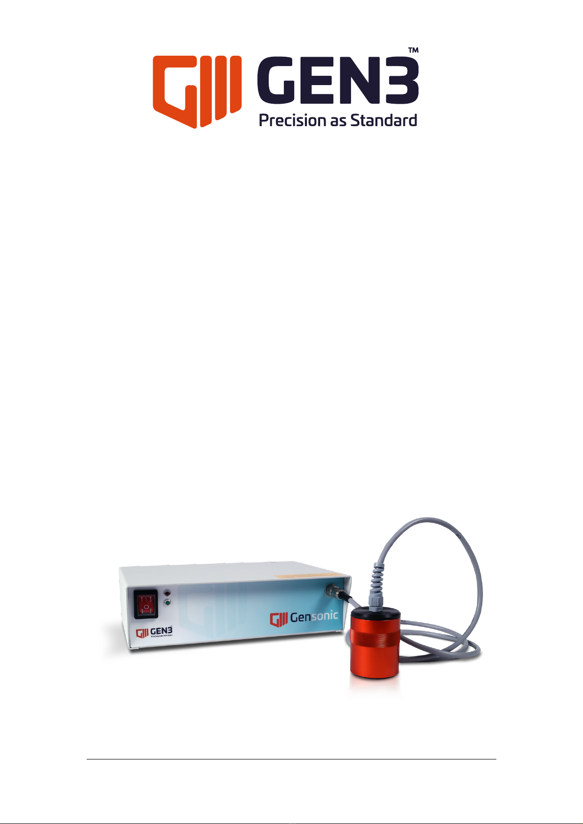
2. General Description
The Gensonic is a manually operated ultrasonic transducer unit for cleaning stencils
used in printing solder pastes and glues.
It can be used either directly on the printer or the stencils can be taken to the
Gensonic stencil cleaning centre.
Screen printed solder pastes tend to compact and trap particles into aperture
corners and lead free solder pastes, that are less dense, tend to demonstrate this
tendency even more.
To clean effectively requires both “chemical” and mechanical agitation. Direct
ultrasonic contact cleaning is the ultimate way to clean SMT stencils with the
minimum amount of cleaning chemistry.
Employing a 40kHz ultrasonic generator, the single transducer head cleans with
great efficiency. However for certain tougher applications, such as partially set glues,
a Gensonic unit with 2 transducer head units should be used.
This cleaning technique requires only minimal amounts of “chemistry” to be used to
reduce environmental impact and cost.
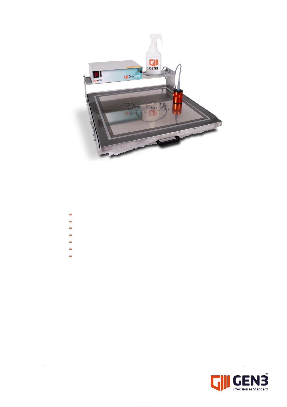
The stencil is placed into the SCC (Stencil Cleaning Centre) frame mounted over a
special foam pad overlain with a disposable paper. At the completion of each
cleaned stencil, simply lift the frame on the supports provided, pull the paper clear,
and cut off.