Genelec 8020C User manual

8020C
Operating Manual 2-7
Betriebsanleitung 8-13
Manuel d’utilisation 14-19
Käyttöohje 20-25
Bruksanvisning 26-31

2 English
General description
The bi-amplified GENELEC 8020C is a compact
two way active monitoring loudspeaker designed
for near field monitoring, mobile vans, broadcast
and TV control rooms, surround sound systems,
home studios, multimedia applications and also for
use with computer soundcards. As an active loud-
speaker, it contains drivers, power amplifiers, active
crossover filters and protection circuitry.
The MDE™ (Minimum Diffraction Enclosure™)
loudspeaker enclosure is made of die-cast alumin-
ium and shaped to reduce edge diffraction. Com-
bined with the advanced Directivity Control Wave-
guideTM (DCWTM), this design provides excellent fre-
quency balance in difficult acoustic environments. If
necessary, the bass response of the 8020C can be
extended with a Genelec subwoofer.
Positioning the loudspeaker
Each 8020C is supplied with an integrated ampli-
fier unit, mains cable and an operating manual. After
unpacking, place the loudspeaker in its required lis-
tening position, taking note of the line of the acoustic
axis. The axes of all loudspeakers should converge
at ear height at the listening position (see Figure 1).
Connections
Before connecting up, ensure that the loudspeakers
and the signal source have been switched off. The
power switch of the 8020C is located on the back
panel (see Figure 3). Connect the loudspeaker to an
earthed mains connection with the supplied mains ca-
ble. Never connect the loudspeaker to an unearthed
mains supply or using an unearthed mains cable.
Audio input is via a 10 kOhm balanced female XLR
connector. An unbalanced source may be used as
long as pin 3 is grounded to pin 1 at the unbalanced
source connector (see Figure 2). Never connect the
8020C to the loudspeaker outputs of a power ampli-
fier or an integrated amplifier or receiver.
Once the connections have been made, the loud-
speakers are ready to be switched on.
Autostart function
The signal sensing Autostart function of the 8020C
powers it up when playback begins. Automatic pow-
ering down of the loudspeaker happens one hour
after the playback has ended and the loudspeaker
goes to standby mode. The power consumption in
standby mode is less than 0.5 watts.The loudspeak-
er will automatically and rapidly start up once an in-
put signal is detected from the source.
Volume control
The input sensitivity of the 8020C can be matched
to the output of the signal source by adjusting the
volume control on the front panel.
Setting the tone controls
The frequency response of the Genelec 8020C can
be adjusted to match the acoustic environment by
setting the tone control switches on the rear panel.
8020C
Active Monitoring System
English 3
The controls are “Treble Tilt”, “Bass Tilt” and “Bass
Roll-Off”. An acoustic measuring system such as
WinMLS or comparable is recommended for ana-
lyzing the effects of the adjustments, however,
careful listening with suitable test recordings can
also lead to good results. Table 1 shows some
examples of typical settings in various situations.
Figure 4 shows the effect of the controls on the
anechoic response.
Treble Tilt
Treble Tilt control (switch 1) attenuates the tre-
ble response of the loudspeaker at frequencies
above 5 kHz by 2 dB, which can be used for
smoothening down an excessively bright sound-
ing system.
Bass Tilt
Bass Tilt control offers three attenuation levels
for the bass response of the loudspeaker below
2 kHz, usually necessary when the loudspeakers
are placed near a wall or other room boundaries.
The attenuation levels are -2 dB (switch 3 “ON”), -4
dB (switch 4 “ON”) and -6 dB (both switches “ON”).
Bass Roll-Off
Bass Roll-Off (switch 2) activates high-pass filter-
ing at 85 Hz to complement the low-pass filters of a
Genelec 7050 subwoofer.This switch should always
be set to “ON” when using the 8020C with these
subwoofers.
The factory setting for all tone controls is “OFF”
to give a flat anechoic response. Always start ad-
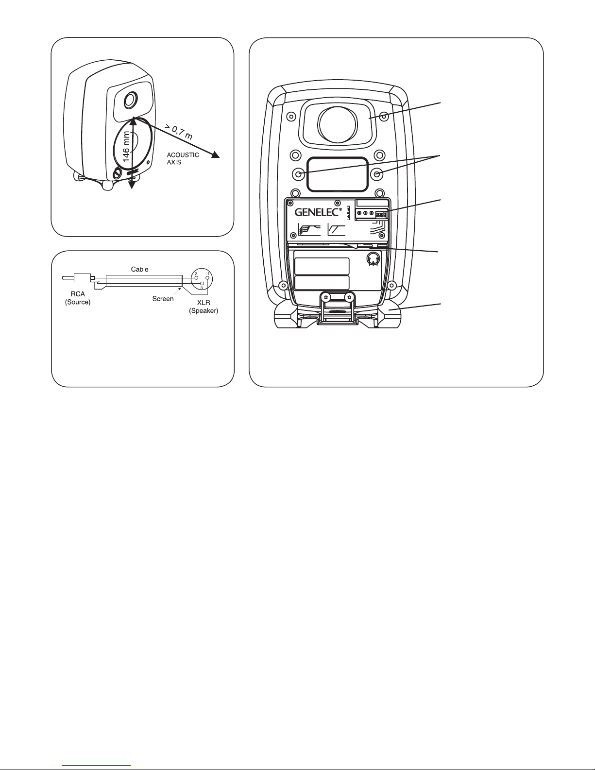
Figure 1: Location of the acoustic
axis
Figure 2: Type of cable needed if
unbalanced source is used (ex-
ample shown is RCA output to the
XLR input)
Figure 3: Control and connector layout on the rear panel
of an 8020C.
MADE IN FINLAND
8020CBI-AMPLIFIED
MONITORING SYSTEM
MAINSINPUT
50 /60Hz50W 230V~
MAGNETICALLY SHIELDED
292-8020BT-6
www.genelec.com
SERIAL NUMBER
+-GND
2
3
IN 1
ON OFF
TO WATER OR MOISTURE.NOUSER SERVICEABLE PARTS
ELECTRIC SHOCK HAZARD. DO NOT OPEN.DONOT SUBJECT
L'INTÉRIEUR REMPLAÇABLE PARL'UTILISATEUR.ADRESSER
RISQUE DE CHOC ÉLECTRIQUE.NEPAS OUVRIR. NE PAS
EXPOSERÀL'EAU OU L'HUMIDITÉ. AUCUN COMPOSANTÀ
USE EARTHED MAINS CONNECTION ONLY.
AVERTISSEMENT
WARNING
INSIDE.REFER SERVICING TO QUALIFIED PERSONNEL.
TOUTERÉPARATIONÀUNPERSONNEL QUALIFIÉ. CET
APPAREIL DOIT ÊTRERACCORDÉÀLATERRE.
292-8030W292-8030W
ALL OFF
65 2k 5k 20k
BASS AND TREBLETILT
-2
-4
-6
0
dB
3
4
3+4
BASS ROLL-OFF
ALL OFF
65 85 500 Hz
TREBLE TILT -2dB
BASS ROLL-OFF-6dB 85Hz
1
dB
0
-6 2
OFF
BASS TILT -4 dB
ON
BASS TILT -6 dB
BASS TILT -2 dB
REFLEX PORT
TONE CONTROLS
CONNECTOR PANEL
AND POWER SWITCH
(HORIZONTAL)
Iso-Pod™TABLE
STAND
THREADS FOR
CEILING AND
WALL MOUNTS

4 English
justment by setting all switches to “OFF” position.
Measure or listen systematically through the dif-
ferent combinations of settings to find the best fre-
quency balance.
Mounting considerations
Align the loudspeakers correctly
Always place the loudspeakers so that their acous-
tic axes (see figure 1) are aimed towards the listen-
ing position. Vertical placement is preferred, as it
minimises acoustical cancellation problems around
the crossover frequency.
Maintain symmetry
Check that the loudspeakers are placed sym-
metrically and at an equal distance from the
listening position. If possible, place the sys-
tem so that the listening position is on the cen-
terline of the room and the loudspeakers are
placed at an equal distance from the centerline.
Minimise reflections
Acoustic reflections from objects close to the loud-
speakers like desks, cabinets, computer monitors
etc. can cause unwanted colouration of the sound
image. This can be minimised by placing the loud-
speaker clear of reflective surfaces. For instance,
putting the loudspeakers on stands behind and
above the mixing console and tilting them down to
point the acoustic axes to ear level at the listening
position usually gives a better result than placing
the loudspeakers on the meter bridge.
Minimum clearances
Sufficient clearance for cooling of the amplifier and
functioning of the reflex port must be ensured if
the loudspeaker is installed in a restricted space
such as a cabinet or integrated into a wall struc-
ture. The surroundings of the loudspeaker must
always be open to the listening room with a mini-
mum clearance of 3 centimeters (13/16”) behind,
above and on both sides of the loudspeaker. The
space adjacent to the amplifier must either be ven-
tilated or sufficiently large to dissipate heat so that
the ambient temperature does not rise above 35
degrees Celsius (95°F)
Mounting options
The Genelec 8020C offers several mounting op-
tions: The Iso-Pod™ (Isolation Positioner/De-
coupler™) vibration insulating table stand allows
tilting the loudspeaker for correct alignment of the
acoustic axis. On the base of the loudspeaker is a
3/8” UNC threaded hole compatible with a stand-
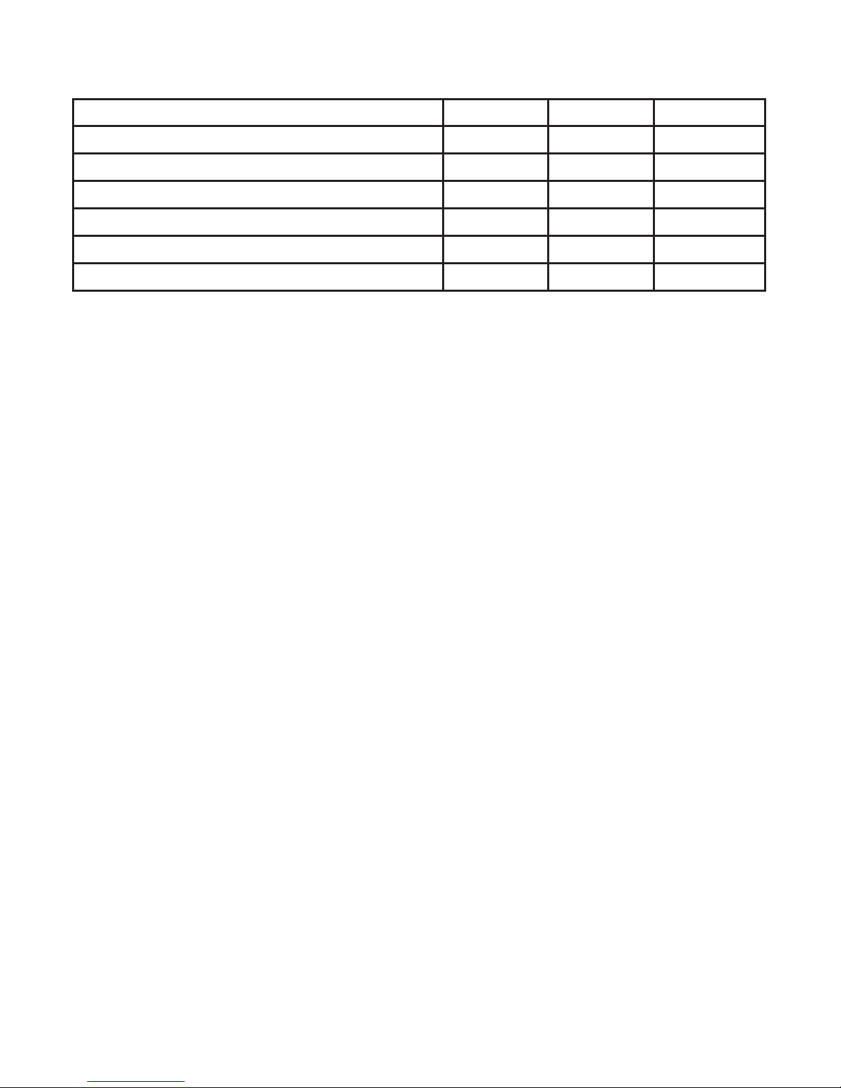
Table 1: Suggested tone control settings for differing acoustical environments
Loudspeaker Mounting Position Treble Tilt Bass Tilt Bass Roll-Off
Flat anechoic response OFF OFF OFF
Free standing in a damped room OFF OFF OFF
Free standing in a reverberant room OFF -2 dB OFF
Near field or console bridge OFF -4 dB OFF
Near to a wall OFF -6 dB OFF
With a 7050B subwoofer See above See above ON

English 5
ard microphone stand. On the rear there are two
M6x10 mm threaded holes for Omnimount®size
20.5 brackets or the keyhole wall mount adapter
provided with the loudspeaker.
Maintenance
No user serviceable parts are to be found within
the loudspeaker. Any maintenance or repair of the
8020C should only be undertaken by qualified ser-
vice personnel.
Safety considerations
Although the 8020C has been designed in accord-
ance with international safety standards, the fol-
lowing warnings and cautions should be observed
to ensure safe operation and to maintain the loud-
speaker under safe operating conditions:
• Servicing and adjustment must only be
performed by qualified service personnel.
The loudspeaker must not be opened.
•
Do not use the loudspeaker with an unearthed
mains cable or an unearthed mains
connection as this may compromise
electrical safety.
• Do not expose the loudspeaker to water or
moisture. Do not place any objects filled with
liquid, such as vases on the loudspeaker or
near it.
• This loudspeaker is capable of producing
sound pressure levels in excess of 85 dB,
which may cause permanent hearing
damage.
• Free flow of air behind the loudspeaker is
necessary to maintain sufficient cooling.
Do not obstruct airflow around the
loudspeaker.
• Note that the amplifier is not completely
disconnected from the AC mains service
unless the mains power cord is removed
from the amplifier or the mains outlet.
Guarantee
This product is guaranteed for a period of two years
against faults in materials or workmanship. Refer to
supplier for full sales and guarantee terms.
Compliance to FCC rules
This device complies with part 15 of the FCC Rules.
Operation is subject to the following two conditions:
This device may not cause harmful interference, and
this device must accept any interference received,
including interference that may cause undesired op-
eration.
Note: This equipment has been tested and found to
comply with the limits for a Class B digital device, pur-
suant to part 15 of the FCC Rules. These limits are de-
signed to provide reasonable protection against harmful
interference in a residential installation. This equipment
generates, uses and can radiate radio frequency ener-
gy and, if not installed and used in accordance with the
instructions, may cause harmful interference to radio
communications. However, there is no guarantee that
interference will not occur in a particular installation. If
this equipment does cause harmful interference to ra-
dio or television reception, which can be determined by
turning the equipment off and on, the user is encour-
aged to try to correct the interference by one or more of
the following measures:
• Reorient or relocate the receiving antenna.
• Increase the separation between the equipment
and receiver.
• Connect the equipment into an outlet on a
circuit different from that to which the receiver is
connected.
• Consult the dealer or an experienced radio/TV
technician for help
Modifications not expressly approved by the manu-
facturer could void the user’s authority to operate the
equipment under FCC rules.

6 English
75
80
85
90
d
B
r
A
40
20k
70
100 200 500 1k 2k 5k 10k Hz
Genelec Oy 8020 (dBr) vs freq (Hz) 6 Apr 05
75
80
85
70 BASS ROLL-OFF
TREBLE TILT
BASS TILT
75
80
85
90
d
B
r
A
40 20k
70 100 200 500 1k 2k 5k 10k Hz
Genelec Oy 8020 (dBr) vs freq (Hz) 6 Apr 05
70
65
0°
60°
15° 30°
45°
Figure 4. The curves show the
effect of the “Bass Tilt”, “Treble
Tilt” and “Bass Roll-Off” controls
on the free field response of the
8020C
Figure 5.The upper curve group
shows the horizontal directiv-
ity characteristics of the 8020C
measured at 1 m. The lower
curve shows the system's power
response.
English 7
AMPLIFIER SECTION
Bass amplifier output power with an 8 Ohm load: 20 W
Treble amplifier output power with an 8 Ohm load: 20 W
Long term output power is limited by driver unit protection
circuitry.
_____________________________________________
Amplifier system distortion at nominal output:
THD <0.08 %
SMPTE-IM <0.08 %
CCIF-IM <0.08 %
DIM 100 <0.08 %
_____________________________________________
Signal to Noise ratio, referred to full output:
Bass >95 dB
Treble >95 dB
_____________________________________________
Mains voltage:100, 120, 220 or 230 V according to region
Voltage operating range: ±10 %
Power consumption: Idle 5 W
Standby <0.5 W
Full output 50 W
SYSTEM SPECIFICATIONS
Lower cut-off frequency, –3 dB: < 65 Hz
_____________________________________________
Upper cut-off frequency, –3 dB: >21 kHz
_____________________________________________
Free field frequency response of system:
66 Hz – 20 kHz (± 2.5 dB)
_____________________________________________
Maximum short term sine wave acoustic output on axis in
half space, averaged from 100 Hz to 3 kHz:
@ 1 m >96 dB SPL
@ 0.5 m >102 dB SPL
_____________________________________________
Maximum long term RMS acoustic output in same
conditions with IEC weighted noise (limited by driver unit
protection circuit): @ 1 m >95 dB SPL
_____________________________________________
Maximum peak acoustic output per pair on top of
console, @ 1 m distance with music material: >105 dB
_____________________________________________
Self generated noise level in free field @ 1m on axis:
< 10 dB (A-weighted)
_____________________________________________
Harmonic distortion at 85 dB SPL @ 1m on axis:
Freq: 50…100 Hz < 3 %
>100 Hz < 0.5 %
_____________________________________________
Drivers: Bass 105 mm (4") cone
Treble 19 mm (3/4") metal dome
Both drivers are magnetically shielded
_____________________________________________
Weight: 3.7 kg (8.1 lb)
_____________________________________________
Dimensions: Height 242 mm (91/2”)
(including Iso-Pod™ table stand)
Height 230 mm (91/16”)
(without Iso-Pod™ table stand)
Width 151 mm (6")
Depth 142 mm (55/8”)
CROSSOVER SECTION
Input connector: Input: XLR female, balanced 10 kOhm,
pin 1 gnd, pin 2 +, pin 3 -
_____________________________________________
Input level for 100 dB SPL output at 1 m:
-6 dBu at volume control max
_____________________________________________
Volume control range:
-80 dB relative to max output
_____________________________________________
Crossover frequency, Bass/Treble: 3.0 kHz
_____________________________________________
Treble tilt control operating range:
0 to –2 dB @ 15 kHz
_____________________________________________
Bass roll-off control operating in a –6 dB step @ 85 Hz
(to be used in conjunction with a 7050 subwoofer)
_____________________________________________
Bass tilt control operating range in –2 dB steps:
0 to –6 dB @ 100 Hz
_____________________________________________
The ‘CAL’ position is with all tone controls set to ‘off’ and
the input sensitivity control to maximum (fully clockwise).

8 Deutsch
Einleitende Beschreibung
Der aktive Zweiweg-Monitor GENELEC 8020C ist ein
extrem kompakt gebauter Lautsprecher für den Einsatz
als Nahfeldmonitor, Ü-Wageneinsatz, Rundfunk- und
TV-Senderegie, Surroundsysteme, Homerecording,
Multimediaanwendungen und auch für den direkten
Anschluss an Soundkarten. Als aktiver Lautsprecher
enthält der 8020C neben den Lautsprecherchassis
auch Endstufen, aktive Frequenzweiche und Schutz-
schaltungen. Das MDE™-Lautsprechergehäuse (Mini-
mum Diffraction Enclosure™) besteht aus Aluminium-
Druckguss und ist so geformt, dass die Schallbeugung
an den Gehäusekanten stark reduziert wird. Zusam-
men mit der DCW™-Schallführung (Directivity Control
Waveguide™) weist dieses Design eine exzellente
Balance des Frequenz-Spektrums in schwieriger akus-
tischer Umgebung auf. Bei Bedarf lässt sich die Tiefen-
wiedergabe des 8020C mit dem GENELEC-Subwoofer
7050B erweitern.
Positionierung der Lautsprecher
Zum Lieferumfang des 8020C gehören die eingebaute
Verstärkereinheit, das Netzkabel und die Betriebsanlei-
tung. Stellen Sie den Lautsprecher nach dem Auspac-
ken an die gewünschte Position und berücksichtigen
Sie die Richtung der akustischen Achse. Die Achsen
aller Lautsprecher sollten in Ohrhöhe auf den Hörplatz
gerichtet sein (siehe Abbildung 1).
Anschlüsse
Vergewissern Sie sich vor dem Anschließen, dass der
Lautsprecher und die Signalquelle ausgeschaltet sind.
Der Netzschalter des 8020C ist auf dessen Rückseite
angeordnet (siehe Abbildung 3). Der Lautsprecher
wird mit dem Stromnetz mittels des mitgelieferten An-
schlusskabels verbunden. Der Lautsprecher darf kei-
nesfalls mit einer Stromversorgung ohne Schutzkontakt
verbunden werden und es darf auch kein Anschlusska-
bel ohne Schutzleiter verwendet werden.
Das Audiosignal wird an die XLR-Buchse (female)
angeschlossen. Der Eingang ist symmetrisch mit einer
Eingangsimpedanz von 10 kOhm. Der Anschluss einer
unsymmetrischen Quelle ist möglich, indem Pin 3 mit
der Masse (Pin 1) auf der unsymmetrischen Seite ver-
bunden wird (Abbildung 2). Der 8020C darf keinesfalls
mit dem Lautsprecherausgang von Endstufen, Vol-
lverstärkern oder Receivern verbunden werden.
Sind alle Verbindungen hergestellt, kann der Lauts-
precher eingeschaltet werden.
Autostart-Funktion
Die signalgesteuerte Autostart-Funktion der Lautsp-
recher schaltet diese ein, sobald die Wiedergabe be-
ginnt. Eine Stunde nachdem die Wiedergabe beendet
ist, schalten sich die Lautsprecher automatisch ab und
wechseln in den Stand by-Modus. Der Stromverbrauch
im Stand by-Modus liegt unter 0,5 Watt. Die Lautspre-
cher starten automatisch und schnell, sobald ein Ein-
gangssignal von der Quelle festgestellt wird.
8020C
Aktives Monitorsystem
Betriebsanleitung

Deutsch 9
Lautstärkeregler
Die Anpassung der Eingangsempfindlichkeit des Laut-
sprechers an den Mischpult-Ausgang oder an andere
Quellen lässt sich mit dem Lautstärkeregler auf der
Frontseite vornehmen.
Einstellung der Filter
Der Frequenzgang des GENELEC 8020C lässt sich
zur Anpassung an die akustische Umgebung justieren.
Dazu sind DIP-Schalter an der Gehäuserückseite an-
geordnet, mit denen die entsprechenden Filter aktiviert
werden können. Die Filter sind „Treble Tilt“, Bass Tilt“
und „Bass Roll-Off“. Empfehlendwert ist der Einsatz
eines akustischen Mess-System wie WinMLS, um das
Ergebnis der Justierung zu überprüfen. Allerdings kann
auch sorgfältiges Hören mit ausgewähltem Audiomate-
rial zu guten Ergebnissen verhelfen, wenn ein Mess-
System nicht verfügbar ist. Die Tabelle 1 zeigt einige
typische Einstellungen für verschiedene Positionen
im Raum. Die Tabelle 4 zeigt die Wirkung der Ein-
stellmöglichkeiten im reflexionsfreien Raum.
Treble Tilt
Das Treble-Tilt-Filter senkt hohe Frequenzen oberhalb
von 5 kHz in 2 dB-Stufen ab (Schalter 1). Es kann ein-
gesetzt werden, wenn eine übertriebene Höhenwie-
dergabe ausgeglichen werden soll.
Bass Tilt
Das Bass-Tilt-Filter erlaubt eine Abschwächung
der Wiedergabe unter 2 kHz in drei Stufen. Diese
Abschwächung kann notwendig werden, wenn der
Lautsprecher nahe einer Wand oder einer anderen
Fläche aufgestellt wird. Die Absenkungsstufen sind
Abbildung 1: Lage der akustischen
Achse
Abbildung 2: Anschlusskabel für
unsymmetrische Tonquellen
(beispielsweise Cinch auf XLR) Abbildung 3: Einstellmöglichkeiten und Anschlüsse auf
der Rückseite des 8020C.
MADE IN FINLAND
8020CBI-AMPLIFIED
MONITORING SYSTEM
MAINSINPUT
50 /60Hz50W 230V~
MAGNETICALLY SHIELDED
292-8020BT-6
www.genelec.com
SERIAL NUMBER
+-GND
2
3
IN 1
ON OFF
TO WATER OR MOISTURE.NOUSER SERVICEABLE PARTS
ELECTRIC SHOCK HAZARD. DO NOT OPEN.DONOT SUBJECT
L'INTÉRIEUR REMPLAÇABLE PARL'UTILISATEUR.ADRESSER
RISQUE DE CHOC ÉLECTRIQUE.NEPAS OUVRIR. NE PAS
EXPOSERÀL'EAU OU L'HUMIDITÉ. AUCUN COMPOSANTÀ
USE EARTHED MAINS CONNECTION ONLY.
AVERTISSEMENT
WARNING
INSIDE.REFER SERVICING TO QUALIFIED PERSONNEL.
TOUTERÉPARATIONÀUNPERSONNEL QUALIFIÉ. CET
APPAREIL DOIT ÊTRERACCORDÉÀLATERRE.
292-8030W292-8030W
ALL OFF
65 2k 5k 20k
BASS AND TREBLETILT
-2
-4
-6
0
dB
3
4
3+4
BASS ROLL-OFF
ALL OFF
65 85 500 Hz
TREBLE TILT -2dB
BASS ROLL-OFF-6dB 85Hz
1
dB
0
-6 2
OFF
BASS TILT -4 dB
ON
BASS TILT -6 dB
BASS TILT -2 dB
BASSREFLEX-
ÖFFNUNG
FILTER-SCHALTER
ANSCHLUSSFELD
UND NETZSCHALTER
(HORIZONTAL)
Iso-Pod™
TISCHFUSS
DECKEN-UND
WANDMONTAGE

10 Deutsch
–2 dB (Schalter 3 auf „ON“), –4 dB (Schalter 4 auf
„ON“) und –6 dB (beide Schalter auf „ON“).
Bass Roll-Off
Der Bass-Roll-Off-Schalter (Schalter 2) aktiviert ein
Hochpassfilter mit einer Grenzfrequenz von 85 Hz, das
als Gegenstück zu dem in die Subwoofer 7050A und
7050B eingebauten Tiefpassfilter fungiert. Der Schalter
muss immer dann aktiviert sein, wenn der 8020C in
Kombination mit einem dieser beiden Subwoofer ein-
gesetzt wird.
Ab Werk sind alle Filter auf „OFF“ gestellt (deak-
tiviert), um einen ebenen Frequenzgang im reflexi-
onsfreien Raum zu erzeugen. Diese Einstellung sollte
immer als Ausgangspunkt für Optimierungen dienen.
Die beste Balance der Frequenzbereiche findet sich
bei Messung oder Hörtest durch versuchsweise Ak-
tivierung und Kombination der verschiedenen Ein-
stellmöglichkeiten.
Aufstellungsvorschläge
Korrekte Monitorausrichtung
Die Monitore sollten so ausgerichtet sein, dass ihre
akustische Achse (siehe Abbildung 1) auf die Hörpositi-
on gerichtet ist. Empfehlenswert ist die vertikale Aufstel-
lung, weil hier die Gefahr von Auslöschungseffekten in
der Nähe der Übergangsfrequenz zwischen Bass- und
Hochtonlautsprecher am geringsten ist.
Symmetrie
Die Monitore sollen symmetrisch und in gleicher Dis-
tanz zum Hörort positioniert werden. Nach Möglichkeit
soll der Hörort auf einer gedachten Linie in der Mitte
zwischen linker und rechter Raumbegrenzungswand
liegen. Die Monitore stehen dann gleich weit von dieser
Linie entfernt.
Minimierung von Reflexionen
Akustische Reflexionen durch in der Nähe der Monitore
befindliche Gegenstände wie beispielsweise Möbel
oder PC-Monitore können unerwünschte klangliche Fä-
rbungen verursachen. Dies kann weitgehend vermieden
werden, wenn die Monitore abseits von reflektierenden
Flächen aufgestellt werden. Vorteilhaft ist es, Monitore
auf direkt hinter dem Mischpult stehenden Stativen an-
zubringen. Dabei sind diese so zu neigen, dass deren
akustische Achse auf die Hörposition in Ohrhöhe ge-
richtet ist. Die beschriebene Stativmontage bringt in der
Regel bessere Ergebnisse als die Positionierung auf
der Meterbridge des Mischpultes.
Tabelle 1: Vorgeschlagene Filtereinstellungen für unterschiedliche akustische Verhältnisse
Lautsprecherposition Treble Tilt Bass Tilt Bass Roll-Off
Reflexionsfreier Raum OFF OFF OFF
Freistehend in gedämpftem Raum OFF OFF OFF
Freistehend in halligem Raum OFF -2 dB OFF
Nahfeldaufstellung oder Meterbridge OFF -4 dB OFF
Wandnahe Positionierung OFF -6 dB OFF
Zusammen mit 7050B Subwoofer Siehe oben Siehe oben ON

Deutsch 11
Minimale Abstände
Die ausreichende Kühlung des Verstärkers und das
Funktionieren der Bassreflex-Öffnung muss sicherge-
stellt sein, wenn der Monitor in einen begrenzten Raum
wie beispielweise ein Möbelstück oder in eine Wand-
nische eingebaut wird. Das den Monitor ungebende
Volumen muss unbedingt in Richtung des Hörraums
offen sein. Der seitliche und obere Abstand sowie der
nach hinten muss mindestens 3 cm betragen. Das an
den Verstärker an der Rückseite angrenzende Volumen
muss entweder so gut belüftet sein, dass die dortige
Umgebungstemperatur nicht über 35°C steigt.
Befestigungsmöglichkeiten
Der 8020C bietet viele Befestigungsmöglichkeiten: Der
Iso-Pod™ (Isolation Positioner/Decoupler™) ermöglicht
die Neigung des Lautsprechers zur korrekten Aus-
richtung der akustischen Achse. Auf der Unterseite
des Monitors befindet sich ein 3/8“-Gewinde, das zu
Standard-Mikrofonstativen passt. Zwei M6-Gewinde-
bohrungen auf der Rückseite (Tiefe 10 mm) passen für
den mitgelieferten Wandhalter und die Halterungen der
Omnimount®-Serie 20.5 .
Instandhaltung
Innerhalb des 8020C befinden sich keine Bauteile, die
vom Anwender gewartet werden können. Eine Instand-
setzung darf nur von qualifiziertem Fachpersonal aus-
geführt werden.
Sicherheitsvorschriften
Der 8020C ist entsprechend internationalen Sicher-
heits-Standards konstruiert. Für einen sicheren Be-
trieb müssen die folgenden Warnhinweise beachtet
werden:
• Instandsetzungen und Einstellungen dürfen nur
von qualifiziertem Fachpersonal ausgeführt
werden. Das Gehäuse darf nicht geöffnet
werden.
• Der8020Cdarfnichtmiteinem
Anschlusskabel ohne Schutzleiter und nicht
an eine Steckdose ohne Schutzerdung
angeschlossen werden. Bei Zuwiderhandlung
droht Unfallgefahr.
• Der8020CdarfnichtWasseroder
Verschmutzung ausgesetzt werden. Mit
Flüssigkeit gefüllte Behältnisse wie Vasen
sollen nicht nahe des 8020C aufgestellt
werden.
• DieserLautsprecherkannPegelvonüber85
dB erzeugen, die bleibende Hörschäden
verursachen können.
• DieungehinderteLuftbewegungander
Gehäuserückseite ist für die Kühlung
notwendig. Deshalb darf die Luftbewegung in
der Umgebung des Gehäuses nicht
eingeschränkt werden.
• BeachtenSie,dassdieVerstärkerelektonikerst
dann vollständig von der Stromversorgung
getrennt ist, wenn das Stromversorgungskabel
aus der Steckdose gezogen wurde.
Garantie
Für dieses Produkt wird eine zweijährige Garantie auf
Material- und Produktionsfehler gewährt. Wenden Sie
sich an Ihren Lieferanten bezüglich der Liefer- und Ga-
rantiebedingungen.

12 Deutsch
75
80
85
90
d
B
r
A
40 20k
70 100 200 500 1k 2k 5k 10k Hz
Genelec Oy 8020 (dBr) vs freq (Hz) 6 Apr 05
75
80
85
70 BASS ROLL-OFF
TREBLE TILT
BASS TILT
75
80
85
90
d
B
r
A
40 20k
70 100 200 500
1k 2k
5k
10k
Hz
Genelec Oy 8020 (dBr) vs freq (Hz) 6 Apr 05
70
65
0°
60°
15° 30°
45°
Abbildung 4. Das Diagramm zeigt
die Auswirkung der Filter “Bass
Tilt”, “Treble Tilt” und “Bass Roll-
Off” auf den Frequenzgang des
8020C.
Abbildung 5. Die obere Kurven-
schar zeigt die horizontale Ab-
strahlcharakteristik des 8020C
gemessen in einem Meter Ab-
stand. Die untere Kurve zeigt
das Bündelungsmaß.
Deutsch 13
VERSTÄRKER
Bass amplifier output power with an 8 Ohm load: 20 W
Treble amplifier output power with an 8 Ohm load: 20 W
Long term output power is limited by driver unit protection
circuitry.
_____________________________________________
Amplifier system distortion at nominal output:
THD <0.08 %
SMPTE-IM <0.08 %
CCIF-IM <0.08 %
DIM 100 <0.08 %
_____________________________________________
Signal to Noise ratio, referred to full output:
Bass >95 dB
Treble >95 dB
_____________________________________________
Mains voltage: 100, 120, 220 or 230 V
according to region
Voltage operating range: ±10 %
Power consumption:
Idle 5 W
Standby <0,5 W
Full output 50 W
TECHNISCHE DATEN
Lower cut-off frequency, –3 dB: < 65 Hz
_____________________________________________
Upper cut-off frequency, –3 dB: >21 kHz
_____________________________________________
Free field frequency response of system:
66 Hz – 20 kHz (± 2.5 dB)
_____________________________________________
Maximum short term sine wave acoustic output on axis in
half space, averaged from 100 Hz to 3 kHz:
@ 1 m >96 dB SPL
@ 0.5 m >102 dB SPL
_____________________________________________
Maximum long term RMS acoustic output in same
conditions with IEC weighted noise (limited by driver unit
protection circuit): @ 1 m >95 dB SPL
_____________________________________________
Maximum peak acoustic output per pair on top of
console, @ 1 m distance with music material: >105 dB
_____________________________________________
Self generated noise level in free field @ 1m on axis:
< 10 dB (A-weighted)
_____________________________________________
Harmonic distortion at 85 dB SPL @ 1m on axis:
Freq: 50…100 Hz < 3 %
>100 Hz < 0.5 %
_____________________________________________
Drivers: Bass 105 mm (4") cone
Treble 19 mm (3/4") metal dome
Both drivers are magnetically shielded
_____________________________________________
Weight: 3.7 kg (8.1 lb)
_____________________________________________
Dimensions: Height 242 mm (91/2”)
(including Iso-Pod™ table stand)
Height 230 mm (91/16”)
(without Iso-Pod™ table stand)
Width 151 mm (6")
Depth 142 mm (55/8”)
FREQUENZWEICHE UND FILTER
Input connector: Input: XLR female, balanced 10 kOhm,
pin 1 gnd, pin 2 +, pin 3 -
_____________________________________________
Input level for 100 dB SPL output at 1 m:
-6 dBu at volume control max
_____________________________________________
Volume control range:
-80 dB relative to max output
_____________________________________________
Crossover frequency, Bass/Treble: 3.0 kHz
_____________________________________________
Treble tilt control operating range:
0 to –2 dB @ 15 kHz
_____________________________________________
Bass roll-off control operating in a –6 dB step @ 85 Hz
(to be used in conjunction with a 7050 subwoofer)
_____________________________________________
Bass tilt control operating range in –2 dB steps:
0 to –6 dB @ 100 Hz
_____________________________________________
The ‘CAL’ position is with all tone controls set to ‘off’ and
the input sensitivity control to maximum (fully clockwise).

14 Français
Description générale
La GENELEC 8020C est une enceinte acoustique
de contrôle active à deux voies extrêmement com-
pacte, conçue pour l’écoute rapprochée, les mobiles,
les salles de contrôle de TV et radiodiffusion, les
systèmes ambiophoniques (surround), les studios
à la maison, les applications multimédia et avec
les cartes de son d’ordinateurs. En tant qu’enceinte
active, elle contient les haut-parleurs, les amplifica-
teurs, les filtres séparateurs actifs et les circuits de
protection. L’ enceinte MDEMC (Minimum Diffraction
EnclosureMC, ou enceinte à diffraction minimale) est
faite d’aluminium moulé sous pression et est dessi-
née pour réduire la diffraction aux arêtes. Combiné
au guide d’onde à directivité contrôlée DCWMC (Di-
rectivity Control WaveguideMC), ce design procure
un excellent équilibre tonal même dans des environ-
nements acoustiques difficiles. Si nécessaire, il est
possible d’étendre la bande passante de la 8020C
vers le bas en ajoutant un caisson grave GENELEC
7050B.
Positionnement de l’enceinte
Chaque 8020C est livrée avec un module d’amplifi-
cation intégré, un cordon d’alimentation secteur et
un manuel d’utilisation. Après l’avoir déballée, pla-
cer l’enceinte à la position d’écoute requise, en te-
nant compte de l’axe acoustique. Les axes acous-
tiques de toutes les enceintes doivent converger
vers la position d’écoute à la hauteur des oreilles
(voir illustration 1).
Connexion
Avant de connecter, s’assurer que l’enceinte ainsi
que les sources audio soient éteintes. L’interrupteur
marche/arrêt de la 8020C est situé sur le panneau
arrière de l’enceinte (voir illustration 3). Brancher
l’enceinte à une prise de courant avec mise à terre
avec le cordon d’alimentation secteur fournit. Ne
jamais brancher l’enceinte à une prise de courant
sans mise à terre, ou utiliser un cordon sans prise
de mise à terre.
L’ entrée audio se fait sur une prise XLR femelle
symétrique à impédance de 10 kOhm. Une source
asymétrique peut être utilisée si on prend le soin
de joindre la broche 3 à la broche 1 à la source
(voir illustration 2). Ne jamais connecter la 8020C
aux bornes de sortie ‘haut-parleurs’ d’un amplifica-
teur de puissance ou d’un amplificateur AV intégré.
Une fois les connexions faites, on peut allumer
l’enceinte.
Allumage automatique
L’enceinte se met sous tension dès détection de la
présence d’un signal audio. A l’opposé, l’enceinte
se mettra automatiquement en mode veille après
une heure d’absence de signal audio. La consom-
mation électrique de l’enceinte en mode veille
est inférieure à 0,5 watts. L’enceinte s’allumera
à nouveau automatiquement et rapidement dès
la détection d’un retour de signal audio depuis la
source.
8020C
Enceinte de contrôle active
Manuel d’utilisation
Français 15
Contrôle de volume
La sensibilité de l’entrée de l’enceinte peut être
ajustée au niveau de sortie du mélangeur, ou autre
source, en tournant la commande de volume sur le
panneau avant de l’enceinte.
Commandes de tonalité
La réponse en fréquence de la 8020C peut s’accor-
der à l’environnement acoustique en ajustant les
commandes de tonalité sur l’arrière de l’enceinte.
Les commandes sont Treble Tilt, Bass Tilt, et Bass
Roll-Off. GENELEC recommande l’utilisation d’un
système de mesure acoustique tel que WinMLS ou
similaire pour analyser l’effet des ajustements, bien
que l’écoute critique avec un signal approprié peut
aussi donner d’excellents résultats si un système
de mesure n’était pas disponible. Le tableau 1 ci-
contre montre des exemples d’ajustements typiques
dans différentes situations. L’illustration 4 montre
l’effet des commandes sur la réponse en chambre
anéchoïque.
Commande Treble Tilt
Le sélecteur Treble Tilt (commutateur 1) atténue de
2 dB la réponse en fréquence au-delà de 5 kHz, ce
qui permet d’adoucir les systèmes trop stridents.
Commande Bass Tilt
Le circuit Bass Tilt procure trois niveaux d’atténua-
tion pour la réponse en basses fréquences de l’en-
ceinte en dessous de 2 kHz, généralement néces-
saire lorsque l’enceinte est placée près d’un mur ou
autres parois d’une pièce. Les niveaux d’atténuation
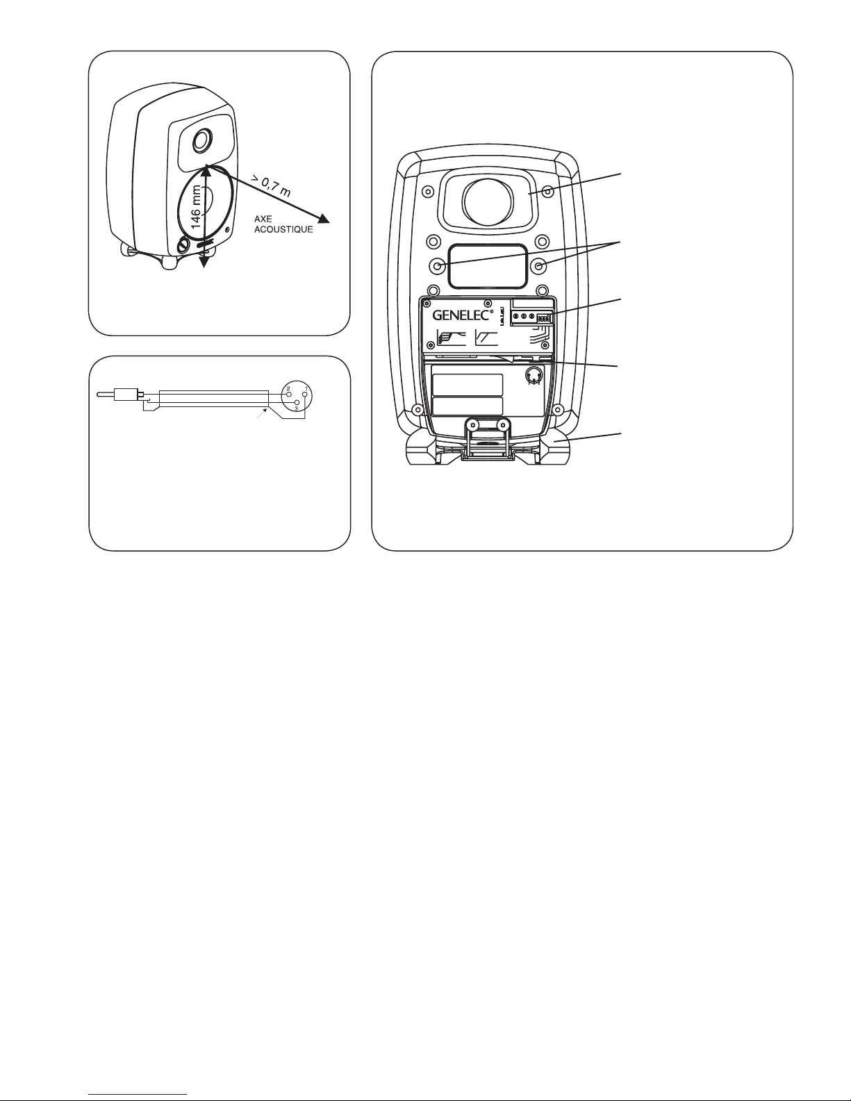
ÉVENT ACCORDÉ
Iso-Pod
SOCLE DE SUPPORT
MC
ORIFICES FILETÉS
POUR SUPPORT
MURAL ET SUPPORT
DE PLAFOND
MADE IN FINLAND
8020CBI-AMPLIFIED
MONITORING SYSTEM
MAINSINPUT
50 /60Hz50W 230V~
MAGNETICALLY SHIELDED
292-8020BT-6
www.genelec.com
SERIAL NUMBER
+-GND
2
3
IN 1
ON OFF
TO WATER OR MOISTURE. NO USER SERVICEABLEPARTS
ELECTRIC SHOCK HAZARD. DO NOT OPEN. DO NOT SUBJECT
L'INTÉRIEUR REMPLAÇABLE PARL'UTILISATEUR. ADRESSER
RISQUE DE CHOC ÉLECTRIQUE.NEPAS OUVRIR. NE PAS
EXPOSERÀL'EAUOUL'HUMIDITÉ.AUCUN COMPOSANTÀ
USE EARTHED MAINS CONNECTION ONLY.
AVERTISSEMENT
WARNING
INSIDE.REFER SERVICINGTO QUALIFIED PERSONNEL.
TOUTERÉPARATIONÀUNPERSONNEL QUALIFIÉ. CET
APPAREIL DOIT ÊTRERACCORDÉÀLATERRE.
292-8030W292-8030W
ALL OFF
65 2k 5k 20k
BASS AND TREBLETILT
-2
-4
-6
0
dB
3
4
3+4
BASS ROLL-OFF
ALL OFF
65 85 500 Hz
TREBLE TILT -2dB
BASS ROLL-OFF-6dB 85Hz
1
dB
0
-6 2
OFF
BASS TILT -4 dB
ON
BASS TILT -6 dB
BASS TILT -2 dB
PANNEAU DE CONNEXION
ET INTERRUPTEUR
GÉNÉRAL
(ACCÈS HORIZONTAL)
COMMANDES DE
TONALITÉ
Cable
Blindage
RCA
(Source) XLR
(Enceinte)
Illustration 1: Position de l’axe
acoustique
Illustration 2:Cablage nécessaire pour
connexion à une source asymétrique
(example ci-dessus d’une sortie RCA
à une entrée XLR)
Illustration 3: Contrôles et disposition des connecteurs sur la
face arrière de la 8020C
16 Français
disponibles sont -2 dB (commutateur 3 en position
ON), -4 dB (commutateur 4 en position ON), -6 dB
(commutateurs 3 et 4 en position ON).
Commande Bass Roll-Off
Le circuit Bass Roll-Off (commutateur 2) active un
filtre passe-haut à 85 Hz pour compléter le filtre
passe-bas du caisson grave GENELEC 7050B ou
7050A. Ce commutateur devrait toujours être en
position ON lorsque la 8020C est utilisée avec ces
caissons graves.
L’ usine livre les enceintes avec tous les commu-
tateurs en position OFF pour une réponse plane
en chambre anéchoïque. On devrait toujours com-
mencer les ajustements avec tous les commuta-
teurs en position OFF. Mesurez ou écoutez sys-
tématiquement les différentes combinaisons pour
trouver le meilleur équilibre tonal.
Considérations lors de l’installation
Positionner les enceintes correctement
Toujours placer les enceintes de façon à ce que leur
axe acoustique (voir illustration 1) soit orienté vers
la position d’écoute. Seul le positionnement vertical
est recommandé, puisqu’il minimise les problèmes
d’annulations acoustiques dans la plage du sépara-
teur de fréquences.
Maintenir la symétrie
S’assurer que les enceintes sont placées symétri-
quement par rapport à l’axe de la pièce, et qu’el-
les sont équidistantes de la position d’écoute. Si
possible, installer le système de façon à ce que
la position d’écoute soit dans l’axe médian de la
pièce et que les enceintes soient équidistantes de
cet axe.
Minimiser les réflexions
Les réflexions acoustiques d’objets proches des
enceintes tel que bureaux, meubles, écrans d’or-
dinateur, etc peuvent estomper et brouiller l’image
sonore. On peut minimiser les réflexions en plaçant
les enceintes loin des surfaces réfléchissantes. Par
exemple, installer les enceintes sur des pieds der-
rière et au–dessus du mélangeur en les inclinant
pour orienter les axes acoustiques vers la position
d’écoute à hauteur des oreilles donne habituelle-
ment de meilleurs résultats qu’en les plaçant sur le
bandeau d’affichage du dit mélangeur.
Emplacement de l’enceinte Treble tilt Bass tilt Bass roll-off
Réponse plane anéchoïque OFF OFF OFF
En champ libre dans une pièce absorbante OFF OFF OFF
En champ libre dans une pièce réverbérante OFF -2 dB OFF
Écoute rapprochée ou sur le bandeau de console OFF -4 dB OFF
Proche d’une paroi OFF -6 dB OFF
Avec le caisson grave 7050B Voir ci-dessus Voir ci-dessus ON
Tableau 1: Recommandation sur les réglages de tonalité dans différents environnements acoustiques

Français 17
Dégagement minimal
On doit prévoir un espace suffisant pour le refroidis-
sement de l’amplificateur et pour le bon fonctionne-
ment de l’évent quand l’enceinte est installée dans
un endroit restreint tel un meuble ou une unité mu-
rale. On doit laisser autour de l’enceinte un espace
libre qui donne sur la position d‘écoute. Un espace
minimal de 3 centimètres (13/16 pouces) doit être
laissé derrière, au-dessus, et de chaque côté de
l’enceinte. L’ espace adjacent à l’amplificateur doit
être ou ventilé ou de dimensions suffisantes pour
dissiper la chaleur de façon à ce que la température
ambiante n’excède pas 35 degrés Celsius (95°F).
Options de montage
La 8020C offre plusieurs options de montage. Le
support de table isolant contre les vibrations Iso-
PodMC (Isolation Positioner/DecouplerMC) permet
d’incliner les enceintes pour un alignement correct
de l’axe acoustique. Le dessous de l’enceinte est
muni d’un orifice fileté 3/8” UNC pour permettre le
montage sur un pied de microphone standard. L’ ar-
rière de l’enceinte comprend deux pas de vis M6x10
mm, conçus pour recevoir un support Omnimount®
de format 20.5 ou l’adaptateur mural fournit avec
l’enceinte.
Entretien
Cet appareil ne comporte aucune pièce pouvant
être réparée par l’utilisateur. Confiez l’entretien ou
la réparation de votre 8020C à un service technique
qualifié.
Considérations sécuritaire
Bien que la 8020C ait été conçue pour répondre aux
normes de sécurité internationales, afin d’assurer
une utilisation sécuritaire et de maintenir l’appareil
en condition d’utilisation sécuritaire, veuillez obser-
ver les avertissements suivants ;
• L’entretienoularéparationnedoitêtre
confié qu’à un service technique qualifié.
L’ enceinte ne doit pas être ouverte.
• Nepasutiliserceproduitavecune
source d’alimentation électrique sans
mise à terre car cela pourrait présenter
un danger pour l’utilisateur.
• Nepasexposerl’enceinteàl’eauouà
l’humidité. Ne pas placer d’objet rempli
de liquide, tel un vase, sur ou près de
l’enceinte.
• Cetappareilpeutgénérerdesniveaux
de pression acoustique de plus de
85 dB SPL, ce qui pourrait entraîner des
dommages permanents à l’ouïe.
• Unecirculationd’airderrièrel’enceinte
est requise afin de permettre le
refroidissement de l’amplificateur. Ne
pas obstruer le flux d’air autour de
l’enceinte.
• Noterquel’enceinten’estpas
complètement débranchée du secteur
tant que le cordon n’est pas débranché
soit de l’enceinte ou de la prise
d’alimentation.
Garantie
Ce produit est garanti pour une période de deux ans
contre les défauts de matériaux ou de fabrication.
Vous référer au fournisseur pour les détails com-
plets des termes de vente et de garantie.

18 Français
75
80
85
90
d
B
r
A
40 20k
70 100 200 500 1k 2k 5k 10k Hz
Genelec Oy 8020 (dBr) vs freq (Hz) 6 Apr 05
75
80
85
70 BASS ROLL-OFF
TREBLE TILT
BASS TILT
75
80
85
90
d
B
r
A
40 20k
70 100 200 500
1k 2k
5k
10k
Hz
Genelec Oy 8020 (dBr) vs freq (Hz) 6 Apr 05
70
65
0°
60°
15° 30°
45°
Illustration 4. Les courbes mon-
trent l’effet des commandes
“Bass Tilt”, “Treble Tilt” et “Bass
Roll-Off” sur la réponse en
fréquence en champ libre de la
8020C.
Illustration 5. Le groupe de
courbes montre les caractéri-
stiques de directivité horizon-
tale de la 8020C mesurées à 1
m. La courbe inférieure montre
la réponse en puissance de
l’enceinte.

Français 19
SECTION AMPLIFICATION
Amplificateur de grave, puissance de sortie avec charge
de 8 Ohm: 20 W
Amplificateur d’aigu, puissance de sortie avec charge de
8 Ohm: 20 W
La puissance de sortie à long terme est limitée par les
circuits de protection des transducteurs
_____________________________________________
Distortion du système d’amplification en niveau nominal:
DHT <0,08 %
SMPTE-IM <0,08 %
CCIF-IM <0,08 %
DIM 100 <0,08 %
_____________________________________________
Rapport signal-bruit pour niveau de sortie maximum:
Grave >95 dB
Aigu >95 dB
_ ______________________________________
Voltage d’alimentation: 100, 120, 220 ou 230 V
selon les régions
Tolérance de l’alimentation: ±10 %
Consommation de puissance:
En attente de signal 5 W
En veille <0,5 W
Sortie maximale 50 W
SPECIFICATIONS DES ENCEINTES
Limite en basses fréquences à –3 dB: < 65 Hz
_____________________________________________
Limite en hautes fréquences à –3 dB: >21 kHz
_____________________________________________
Réponse en fréquence en champ libre:
66 Hz – 20 kHz (± 2.5 dB)
_____________________________________________
Niveau sinusoidal maximum à court terme, dans l’axe,
demi espace, moyenne de 100 Hz à 3 kHz:
@ 1 m >96 dB SPL
@ 0,5 m >102 dB SPL
_____________________________________________
Niveau RMS maximum à long terme, dans les conditions
ci-dessus avec un signal IEC pondéré (limité par le circuit
de protection du transducteur): @ 1 m >95 dB SPL
_____________________________________________
Niveau maximum en crête, par paire, au-dessus du
bandeau de console @ 1 m de l’ingénieur avec un signal
musical: >105 dB
_____________________________________________
Bruit de fond en champ libre @ 1 m dans l’axe:
< 10 dB (pondération-A)
_____________________________________________
Distortion harmonique à 85 dB SPL @ 1 m dans l’axe:
Freq: 50…100 Hz < 3 %
> 100 Hz < 0.5 %
_____________________________________________
Transducteurs:
Grave 105 mm (4”) cône
Aigu 19 mm (3/4”) dôme en métal
Les deux tranducteurs sont blindés magnétiquement
_____________________________________________
Poids: 3,7 kg (8.1 lb)
_____________________________________________
Dimensions:
Hauteur 242 mm (91/2”)
(avec socle de support)
Hauteur 230 mm (91/16”)
(sans socle de support)
Largeur 151 mm (6")
Profondeur 142 mm (55/8”)
SECTION FILTRES
Connection:
Entrée: XLR femelle, symétrique 10 kOhm,
broche 1 terre, broche 2 +, broche 3 -
_____________________________________________
Niveau d’entrée pour un signal de sortie de 100 dB SPL
à 1 m:
-6 dBu avec contrôle de volume au max
_____________________________________________
Plage du contrôle de volume:
-80 dB relatif à la sortie maximum
_____________________________________________
Fréquence de coupure grave/aigu: 3.0 kHz
_____________________________________________
Contrôle du Treble tilt de: 0 à–2 dB @ 15 kHz
_____________________________________________
Contrôle du Bass roll-off de –6 dB @ 85 Hz
(à utiliser conjointement avec un caisson grave 7050B)
_____________________________________________
Contrôle du Bass tilt par pas de –2 dB:
0 à –6 dB @ 100 Hz
_____________________________________________
La position ‘CAL’ se réfère à tous les contrôles de tonalité
sur ‘off’ et le contrôle du volume sur maximum (butée
sens horaire).

20 Suomi
Yleistä
GENELEC 8020C on pienikokoinen, mutta erittäin
suorituskykyinen aktiivikaiutin. Se soveltuu lähikent-
tämonitoriksi äänitysstudioihin, ulkolähetysautoihin,
radio– ja TV–lähetysten äänen tarkkailuun, julkisiin
tiloihin, installaatioihin, kotistudioihin, multimedia-
tuotantoon, tietokoneiden audiojärjestelmiin ja koti-
teattereihin. Kaiuttimeen on integroitu päätevahvis-
timet, säädettävä aktiivinen jakosuodin ja kaiutinele-
menttien ylikuormitussuojauspiirit. Uusi Minimum
Diffraction Enclosure™ (MDE™)–kotelorakenne ja
edelleen kehitetty Directivity Control Waveguide™
(DCW™)–suuntain takaavat tasapainoisen toiston
vaikeissakin akustisissa ympäristöissä. Tarvitta-
essa 8020C:n bassotoistoa voidaan tukea Genelec
7050–subwooferilla.
Liitännät
Kaiuttimien mukana toimitetaan suojamaadoitetut
verkkovirtajohdot. Älä kytke kaiutinta suojamaadoit-
tamattomaan pistorasiaan.
Ennen kuin teet mitään kytkentöjä, varmista, että
kaikista laitteista on kytketty virta pois. Kaiuttimen
virtakytkin on sijoitettu liittimien väliin kaiuttimen
takalevyyn. Audiosignaalia varten kaiuttimissa on
balansoitu 10 kOhm:in XLR–liitin, johon ääniläh-
teeltä tuleva signaalijohto kytketään. Ellei ääniläh-
teessä ole balansoitua antoliitäntää, voidaan käyt-
tää kuvan 2 mukaisesti kytkettyä signaalijohtoa.
Genelec 8020C–aktiivikaiuttimet saa kytkeä
ainoastaan linjatasoista signaalia antavaan ääni-
lähteeseen, ei milloinkaan päätevahvistimen tai
integroidun vahvistimen kaiutinliittimiin.
Kytke virta päälle kun kaikki liitännät on tehty.
8020C
Aktiivikaiutin
Other manuals for 8020C
1
Table of contents
Languages:
Other Genelec Speakers manuals

Genelec
Genelec 1038B User manual

Genelec
Genelec 1032C User manual

Genelec
Genelec GLM 4 User manual

Genelec
Genelec AOW312 User manual

Genelec
Genelec 8030 User manual

Genelec
Genelec G Two User manual

Genelec
Genelec 1234APM User manual

Genelec
Genelec AutoCal 8130A User manual

Genelec
Genelec SAM 1238DF User manual

Genelec
Genelec M040 User manual

Genelec
Genelec aiw26b User manual

Genelec
Genelec 1022A User manual

Genelec
Genelec 1238CFM User manual

Genelec
Genelec G One User manual

Genelec
Genelec 4430A User manual

Genelec
Genelec 1032B User manual

Genelec
Genelec G Three User manual

Genelec
Genelec 1037C User manual

Genelec
Genelec 1238df User manual

Genelec
Genelec 1035B User manual


