General Awnings IMPERIAL LATTICE-6 GUTTER User manual

. 1 Imperial Marquee Installation Instructions
Before You Begin:
• Consult your local building department for any required permits
You may be required to obtain a building permit for this structure. Contact your local building department
for details.
• Read instructions thoroughly
Please read all instructions and notes carefully prior to assembly. We are not responsible for replacing
parts lost or damaged due to incorrect assembly.
• A solid attachment is required for all existing structures
All points of attachment to existing structures (such as house, deck, or patio) must be into solid, structurally
sound, and secure material. Example: wood or metal studs, joists, headers, plates, or sills.
Attachment may be made to block, concrete, brick, or stone veneer with suitable anchors, purchased
separately. Note: Failure to properly fasten unit to wall, deck, porch, or patio may result in damage to the
unit, damage to the structure it is attached to, and could cause serious bodily injury.
• Check for all parts
Use the Parts and Hardware List to check for any missing parts. To prevent scratching of painted materials,
place on a tarp or other protective material.
• Assistance is recommended during entire assembly.
CAUTION
• Proper site preparation is required.
• Standard shade structure design does not include additional loads such as hanging heavy plants,
swings, or other objects.
• DO NOT stand or sit on the shade structure roof.
• Repair or replace broken parts immediately.
• This kit contains parts with metal edges. Please be careful when handling.
Contact us at:
888.330.3115 or
www.generalawnings.com
IMPERIAL LATTICE - 6” GUTTER
INSTALLATION INSTRUCTIONS

. 2 Imperial Marquee Installation Instructions
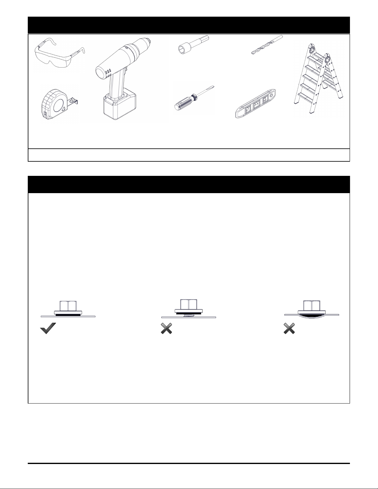
Tools Needed for Installation
Installation Notes and Tips
• Complete site preparation before beginning assembly.
• DO NOT attempt to assemble on a day with strong winds.
• Have assistance nearby to lift and secure parts in place.
• Cutting and drilling metal components will cause shavings which must be carefully removed by
sweeping or brushing. If this is not done, the metal shavings will rust and stain the surface finish.
• It is recommended to lower the speed of electric drills during this installation. Installing Tek screws at
a high RPM may cause the Tek screws to become damaged or break during installation.
• Avoid over-driving, under-driving, or driving at an angle to properly install fasteners. Over-driven
fasteners can depress the material and allow water to collect around the fastener, which will corrode
the surface finish. Under-driven fasteners can cause leaks and may back out over time.
• The center-to-center spacing of the roof panel locks must be maintained as the panels are installed.
If this is not done, problems may not show up until towards the end of the installation when parts may
appear to be cut too short or too long. If this happens, check each roof panel spacing and re-set if
necessary.
• We strongly recommend using a high grade sealant, such as our 100% silicone caulk and sealant.
Caulking should be applied uniformly and without skips. A poor caulking job can cause leaks.
Safety Glasses
Tape Measure Carpenters Level
Electric Drill Screw Driver
Flat & Phillips Ladder
Socket / Hex Head Driver
Sizes: 1/4”, 5/16”,
3/8”, 9/16”
Drill Bit
Sizes: 5/16”, 7/16”
Other Required Tools: Gloves, Chalk Line, Silicone Caulking
Recommended Tools: Rubber Mallet, Carpenters Square, Pliers, Metal Hack Saw
CORRECT TOO LOOSE TOO TIGHT
Note: These are basic installation guidelines for our standard load units and may not be suitable to your specific
installation. It is important to follow all local and national building codes when installing any exterior improvement
product. If you have questions regarding the proper installation of any of our products, please contact us at 1-
888-330-3115 or [email protected].

. 3 Imperial Marquee Installation Instructions
1.5” x 1.5” Lattice Tube
Part Code: 11243
ALattice Splice Tube
Part Code: 11270
BLattice Splice Bracket
Part Code: 50101
C
Lattice Splice Strap
Part Code: xxxxx
D2” Dia. Projection Tube
Part Code: 30300
E1” Sq. Support Tube
Part Code: 30308
F
Mounting Bracket
Part Code: 50128
HSlide Fitting Bracket
Part Code: 50130
I
Fascia Fitting Bracket
Part Code: 50156
G
Parts List
NOTE: Length and quantity of parts will vary based on the size of the awning.

. 4 Imperial Marquee Installation Instructions
#8 x 3/4” Screw Tek 2
Part Code: 20123
AA
6” Corner Cap - Outside
Part Code: 60670
L
Parts List (continued)
NOTE: Length and quantity of parts will vary based on the size of the awning.
Hardware List
Screws shown actual size.
CC
BB 3/8” x 2” Bolt
Part Code: 20414
DD 3/8” Hex Nut
Part Code: 20562
Scupper
Part Code: 90241
K
Gutter Fascia
Part Code: 11143
J
3” Corner Cap - Inside
Part Code: 60671
M
#12 x 1-1/4” Screw Tek 5
Part Code: 20201
EE 3/8 x 1” Bolt
Part Code: 20753
NLattice Angle Trim
Part Code: 11402

. 5 Imperial Marquee Installation Instructions
Gutter Splice (Lower)
Part Code: 60668
S
1/4” x 1/2” Bolt
Part Code: 20751 GG 1/4” Hex Nut
Part Code: 20503
OPTIONAL Parts
NOTE: Length and quantity of parts will vary based on the size of the awning.
Gutter Splice (Upper)
Part Code: 60669
TGutter Extension
Part Code: 11148
R
FF

. 6 Imperial Marquee Installation Instructions
GUTTER SPLICE—OPTIONAL
Complete this step only if gutter (J) is in two or more pieces.
Apply a generous amount of caulk to the back and bottom of the provided gutter splices (T) and (S) to
prevent leaks. Insert an equal amount of the splices into the ends of the gutters.
Attach gutter (J) to gutter splice (T) and (S) using
(12) #8 x 1/2” bolts (GG) and #8 nuts (HH) as
shown.
GUTTER EXTENSIONS—OPTIONAL
If you received optional gutter extensions (R) with your order, fit the tabs at the top of the extension into
the slots at the bottom of gutter (J). Slide extension (R) until the ends are flush with the gutter.
Typically, gutter extensions (R) are only installed on the front and both sides of the cover. Be sure to
position the extensions so that the square ends are against the mounting surface.

. 7 Imperial Marquee Installation Instructions
1
STEP 1
Position an outside corner cap (L) (6” long) to both of the mitered ends of the front and rear gutters (J)
using (2) #8 x 3/4” screws (AA) per corner. Front Gutter caps (L) can be attached at step 10
Mark a level line on the mounting surface at the desired mounting height. Recommended minimum of 8”
above any out-swinging door.
Align the holes in the rear gutter (J) with the level line and attach fascia fitting brackets (G) to the mounting
surface using appropriate anchors purchased separately, (2) per bracket. Minimum anchor capacity for
standard load models is 800 lbs. shear strength and 800 lbs. pull-out strength. Higher capacity anchors
may be required for higher load models.
Attach the rear gutter (J) to the mounting surface using appropriate anchors purchased separately.
Minimum anchor capacity for standard load models is 350 lbs. shear strength.
NOTE: Review the Safety Information on page 2 and your local building codes for anchor bolt
requirements.
1.1 1.2

. 8 Imperial Marquee Installation Instructions
STEP 2
Position mounting bracket (H) directly above each fascia fitting bracket (G). To determine the appropriate
mounting height, subtract 12” from the canopy projection.
Attach mounting bracket (H) to the mounting surface using appropriate anchors purchased separately, (2)
per bracket. Minimum anchor capacity for standard load models is 800 lbs. shear strength and 800 lbs.
pull-out strength. Higher capacity anchors may be required for higher load models.
2
2.22.1

. 9 Imperial Marquee Installation Instructions
STEP 3
Fit projection gutter (J) behind corner caps (L) & (M) at each end of gutter (J). Attach the projection
gutter to the corner caps using (4) #8 x 3/4” screws (AA) as shown in (3.1 & 3.2 below). Repeat for
remaining projection gutter (J). Notice NOTE in image 3.3.. Attach items (M) & (N) Lattice Angles to
projection gutter. Repeat steps (3.3 & 3.4) for all projection gutter sections. To achieve easier Lattice
Tube installation only attach bottom angle (N), position each Lattice Tube then place last angle (N) on
top of Lattice Tubes and secure. This suggestion is shown in Step 5 & 6.
3.1 3.2
3.3 3.4

. 10 Imperial Marquee Installation Instructions
STEP 4
Position Lattice Splice bracket [C] directly under Fascia bracket on Rear Gutter & attach using
(2) #12 x 1-1/4” Tek Screws. Shown on image 4.1
Slide Lattice Splice Tube (B) onto end of Splice bracket [C], & attach using (2) #12 x 1-1/4” Tek
Screws. Shown on image 4.2
STEP 5
Attach Bottom Lattice Tube Angle (N) to Splice Tube using (4+) #8 x 3/4” screws (AA). Shown on image 5.1
below.
Position Lattice Tubes (A) at desired even spacing on bottom angle (N). Shown on image 5.2
4.1 4.2
5.1 5.2

. 11 Imperial Marquee Installation Instructions
STEP 6
Attach Top Lattice Tube Angle (N) to Splice Tube using (4+) #8 x 3/4” screws (AA). Shown on image 6.1
Secure Lattice Tubes (A) at desired even spacing on bottom angle (N), using (4+) #8 x 3/4” screws (AA).
Shown on image 6.2
STEP 7
Attach Lattice Splice Strap (D) to Splice tube using #12 x1-1/4” Tek Screw. (BB) Shown in image 7.1
Next attach Projection Tube [E] through Splice Straps and into Rear Fascia Bracket. Secure using #12 x1-
1/4” Tek Screw. (BB) Shown in image 7.2
Now position Slide Fitting Bracket [I] at requested distance from wall. Refer to Engineering prints for custom
distance.
7.1
6.1 6.2
7.2

. 12 Imperial Marquee Installation Instructions
STEP 8
Attach Projection Tube [E] to Fascia Fitting bracket (G)
on Rear Gutter using (2) #12 x 1-1/4” Tek Screws. (BB)
Shown in image 8.1 & 8.5
Position Diagonal support tube (F) between slide fitting
bracket (I) and mounting bracket (H). Attach the support
tube to the brackets using 3/8” x 2” bolt (CC) and 3/8” nut
(DD) at both ends. Shown in images 8.2 & 8.3
Refer to Engineering prints to position Slide Fitting
Bracket [I] at requested distance from wall. Secure using
(4) #12 x 1-1/4” Tek Screws. (BB) Shown in image 8.4
8.1 8.2
8.3
8.4 8.5

. 13 Imperial Marquee Installation Instructions
AFTER STEP 3 & 4
*IMPORTANT* TO HAVE PROJECTION SUPPORTS. We suggest Ladders and a 2x4 as most common.
Position Projection Gutter & Lattice Splice directly under support braces first resting on (2x4 support).
Then proceed to Steps 5 & 6. Before applying screws #8 x 3/4” screws (AA) to Lattice’s, position tubes
left to right as desired to ensure the correct spacing from projection gutter.

. 14 Imperial Marquee Installation Instructions
STEP 9
Position Front gutter (J) on support brace Fascia Brackets (G). Field Drill Holes in Front Gutter for
(2) 3/8” x 1” Bolt (EE)(DD). Attach the Front gutter using (2) 3/8” x 1” Bolt & Nut. (EE) (DD) shown in
images 9.1 & 9.2
9
9.2
9.1

. 15 Imperial Marquee Installation Instructions
STEP 10 - SCUPPER INSTALLATION
If optional downspout kit was received with your order, you may not have received scupper (K). Follow the
separate downspout assembly instructions attached.
Determine the desired location to drain water from gutter (J). Cut a hole no bigger than 2” diameter in the
bottom of the gutter. Alternatively, you may drill several small holes in a rectangular pattern no bigger
than 2” x 3”.
Apply a generous bead of caulk around the top flange of scupper (K). Attach the scupper to gutter (J)
using (2) #8 x 3/4” screws (AA).
Repeat for any remaining scuppers (K).
Assembly Completed
10

REAR GUTTER/DS
CONNECTION DETAIL
NTS
Existing Structure
1. Drill 2 3/4" dia. h le in gutter at
desired drainage l cati n.
2. Attach Gutter Flange t b tt m
f Gutter using Tek srews. Next
attach D wnsp ut t Gutter Flange
using Tek screws.
Gutter Flange
Existing Structure
REAR DS/BOTTOM FLANGE
CONNECTION DETAIL
NTS
3. Attach B tt m Flange t
D wnsp ut using Tek screws.
4. Anch r D wnsp ut t structure
with Brackets pr vided.
3" D wnsp ut
REAR MOUNTED DSA
NTS
Existing
Structure
Supp rt Brace
(2 Typ.)
Gutter
3" D wnsp ut
Assembly
GUTTER PROFILE
6"
4"
3"
Downspout Installation Instructions
Rear Mounted

FRONT GUTTER/DS
CONNECTION DETAIL
REAR DS/BOTTOM FLANGE
CONNECTION DETAIL
NTS
NTS
DS Splice
Elb w
Gutter
Gutter
Flange
3" D wnsp ut
1. Drill 2 3/4" dia. h le in gutter at
desired drainage l cati n.
2. Attach Gutter Flange t b tt m
f Gutter using Tek srews. Next
attach Elb w t Gutter Flange using
Tek screws. Next attach DS Splice
t Elb w and then the Elb w using
Tek screws. Attach D wnsp ut t the
Elb w using the Tek screws pr vided.
3. Attach B tt m Flange t
D wnsp ut using Tek screws.
4. Anch r D wnsp ut t structure
with Brackets pr vided.
Elb w
3" D wnsp ut
FRONT MOUNTED DSA
NTS
Existing
Structure
Gutter
Supp rt Brace
(2 Typ.)
3" D wnsp ut
Assembly
GUTTER PROFILE
6"
4"
3"
Downspout Installation Instructions
Front Mounted
Table of contents
Popular Outdoor Furnishing manuals by other brands

Courtyard Creations
Courtyard Creations RTS016G Assembly instructions

Forever Redwood
Forever Redwood WOODEN SPA STEP Assembly instructions

Gardenline
Gardenline 22098-18 user manual

Plus
Plus 187710 manual

Shade N' Shelters
Shade N' Shelters Lexington LEX/GAZ-2 owner's manual

Stratco
Stratco Outback Flat Attached installation guide

Palram
Palram CANOPIA OASIS How to assemble

Gumax
Gumax Veranda Mounting instructions

Sunjoy
Sunjoy A102009100 Assembly and safety instructions

Weltevree
Weltevree Wheelbench Accoya product manual

Moon Valley
Moon Valley Cedar Works M-100 Product Care & Maintenance Guidelines

Zippity
Zippity Classica Vinyl Mailbox Post Assembly instructions