General DMM30 User manual

8-FUNCTION
DIGITAL MULTIMETER
WITH NCV DETECTION
USER’S MANUAL
DMM30
Please read this manual carefully and thoroughly before using this product.

TABLE OF CO TE TS
Key Features . . . . . . . . . . . . . . . . . . . . . . . . . . . . . . . . . . . 3
What’s in the Package . . . . . . . . . . . . . . . . . . . . . . . . . . . . 3
Product Overview . . . . . . . . . . . . . . . . . . . . . . . . . . . . 3 –4
Safety Instructions . . . . . . . . . . . . . . . . . . . . . . . . . . . 4 –6
Setup Instructions . . . . . . . . . . . . . . . . . . . . . . . . . . . . . . . 7
Install Battery . . . . . . . . . . . . . . . . . . . . . . . . . . . . . . . . 7
Operating Instructions . . . . . . . . . . . . . . . . . . . . . . . . 7 – 11
General Instructions . . . . . . . . . . . . . . . . . . . . . . . . . . . 7
Holding Readings . . . . . . . . . . . . . . . . . . . . . . . . . . . . . 7
Measuring AC or DC Voltage . . . . . . . . . . . . . . . . . 7 –8
Measuring DC Current . . . . . . . . . . . . . . . . . . . . . . 8 –9
Measuring Resistance . . . . . . . . . . . . . . . . . . . . . . . . . 9
Checking for Continuity . . . . . . . . . . . . . . . . . . . . 9 – 10
Checking the Integrity of a Diode . . . . . . . . . . . . . . . . 10
Checking Battery Voltage . . . . . . . . . . . . . . . . . . 10 – 11
sing the NCV Detector . . . . . . . . . . . . . . . . . . . . . . . 11
Specifications . . . . . . . . . . . . . . . . . . . . . . . . . . . . .11 – 12
Operating & Maintenance Tips . . . . . . . . . . . . . . . . . . . . 13
Warranty Information . . . . . . . . . . . . . . . . . . . . . . . . . . . 14
Return for Repair Policy . . . . . . . . . . . . . . . . . . . . . . . . . 15
2
KEY FEATURES
• 8 functions, 22 ranges
• Measures AC/DC voltage, DC current and resistance
• Also checks continuity, diode integrity and battery voltage
• Non-contact voltage (NCV) detection
• ETL certified safe for CAT II 600V use
• Jumbo 3-1/2 digit (2000 count) LCD with 7/8 in. (22mm) high digits
• Powered by “9V” battery (included)
• Low battery indication • 1-year limited warranty
WHAT’S I THE PACKAGE
The meter is supplied in a blister pack. A cavity on the blister card
contains a pair of double-insulated test leads. A “9V” battery is
pre-installed in a compartment in the back of the unit.
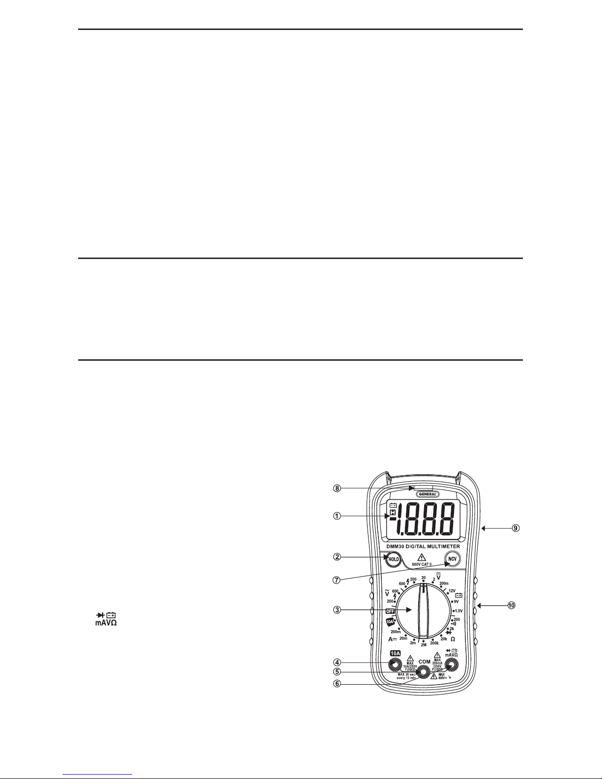
PRODUCT OVERVIEW
ig. 1 shows the labels and positions of the controls, LCD and physical
structures of the DMM30. ig. 2 shows all possible indications on the
LCD. amiliarize yourself with the functions and meanings of all
controls, indications and connectors
before moving on to the Setup
Instructions and Operating Instructions.
1) LCD 2) HOLD button
3) Rotary function switch
4) 10A input jack
5) COM jack
6) jack (for all inputs except
currents >200mADC)
7)
NCV
button
8) NCV detector and visual indication
9) Battery compartment (on back)
10) lip-up stand (on back)
3
Fig. 1. The ontrols, display and
physi al features of the DMM30
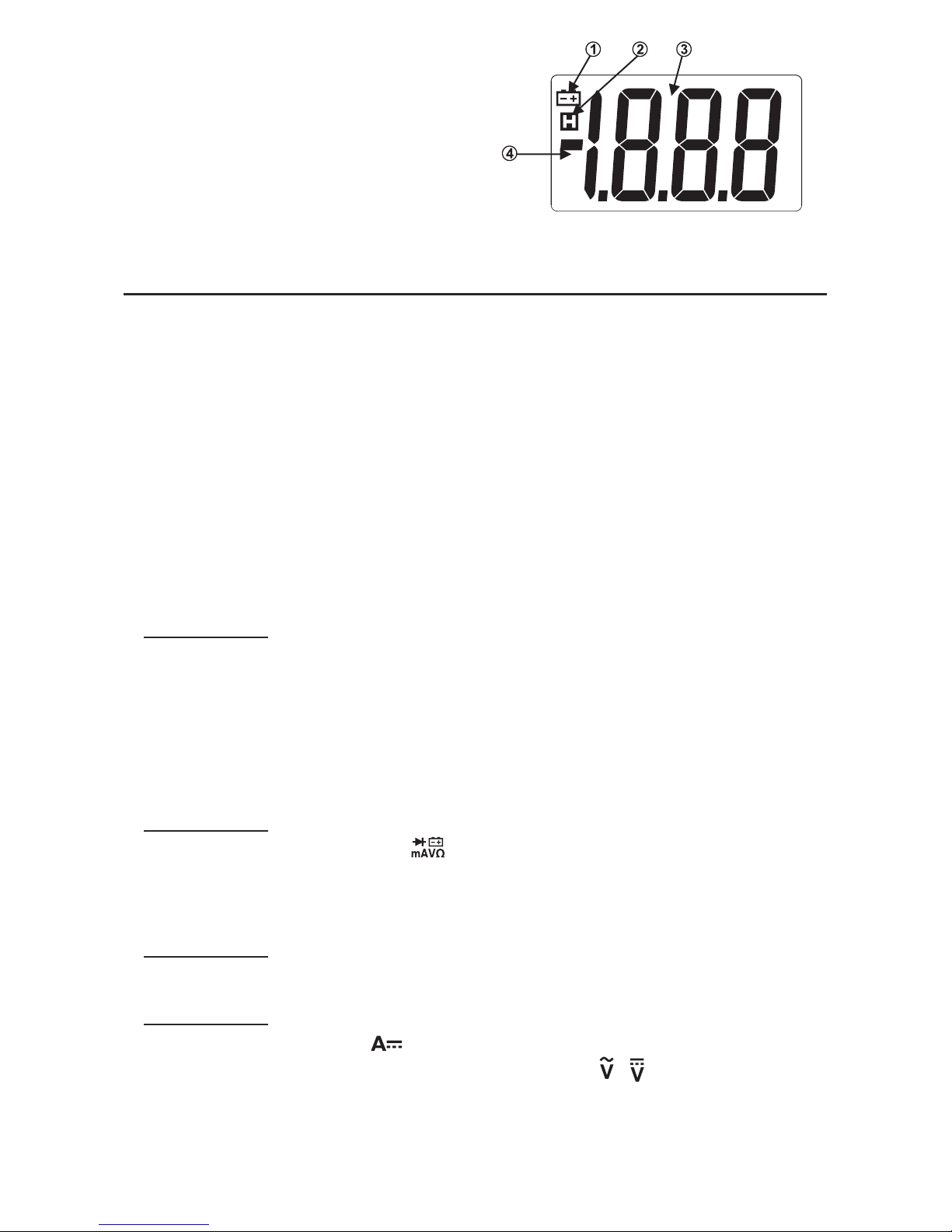
1) Low battery indicator
2) Indicates that the displayed
value is a held reading
3) Measured value
4) Negative polarity indicator
SAFETY I STRUCTIO S
Warning
To avoid possible ele tri sho k or personal injury, and to avoid
damaging the meter or the equipment under test:
• Do not use the meter in any way not detailed in this manual or the
meter's safety features may be compromised.
• Before using the meter, inspect the case. Do not use the meter if it is
damaged. Look for cracks or missing plastic. Pay particular attention
to the insulation around the connectors.
•
WARNING
Inspect the test leads for damaged insulation or
exposed metal. Check the test leads for continuity. Replace damaged
test leads before using the meter.
• Verify the meter’s operation by measuring a known voltage. Do not
use the meter if it operates abnormally. Protection may be impaired.
When in doubt, have the meter serviced.
•
WARNING
Do not apply more than the rated voltage, as marked
on the meter, between the and
COM
jacks or between any jack
and ground. Also do not input more than the rated current, as
marked on the meter, through the
10A
jack.
•
WARNING
Do not measure voltages above 600V in Category II
installations.
•
WARNING
Do not attempt to measure voltage with the rotary
function switch in any or Ω position. Never attempt to measure
current with the rotary function switch in any , or Ω position.
4
Fig. 2. All possible
display indi ations

• Use caution when working with voltages above
42VACRMS, or 60VDC. These voltages pose a shock hazard.
• Use the proper terminals, function and range for all measurements.
•
WARNING
Do not operate the meter around explosive gas, vapor,
or dust.
•
WARNING
When using the probes, keep your fingers behind the
finger guards. Do not touch the metal probes of the test leads when
making a measurement.
• When making connections, connect the black (–) test lead before
connecting the red (+) test lead; when disconnecting, disconnect the
red (+) test lead before disconnecting the black (–) test lead.
• Disconnect circuit power and discharge all high-voltage capacitors
before measuring/testing resistance, continuity, diodes, or
capacitance.
• or all DC functions in both auto and manual ranging mode, to avoid
the risk of shock due to possible improper reading verify the
presence of any AC voltages by first using the AC function. Then
select a DC voltage range equal to or greater than the AC range.
• Before measuring current, turn off power to the circuit before
connecting the meter.
• Do not operate the meter with the case (or part of the case)
removed.
• Use only (1) “9V” battery, properly installed in the battery
compartment, to power the meter. Do not use rechargeable
batteries.
• Replace the battery as soon as the low battery indicator “ ”
appears. Operated with a weak battery, the meter might produce
false readings that could lead to electric shock and personal injury.
• Remove the test leads from the meter before opening the meter
case or battery compartment.
5

Electrical Symb ls Used On the Meter and
In This Manual
Symbol Des ription Symbol Des ription
AC (Alternating use
Current)
DC Double
(Direct Current) Insulated
Caution, risk of electric Risk of danger. Important
shock. Hazardous information. Refer to the
voltage. manual.
Low battery indication
(when shown Earth ground
on LCD)
Diode Continuity
Beeper
AC or DC ΩResistance
CAT II or measurements
made on household
appliances, portable tools
and similar devices plugged
into standard wall outlets
(110 VAC in the U.S. and
220 VAC in Europe)
6

SETUP I STRUCTIO S
INSTALL BATTERY
Turn the meter over to gain access to the battery compartment.
To open the ompartment:
1)
Use a small Phillips-head screwdriver to remove the single screw near
the top of the one-piece battery compartment cover/flip-up stand.
2) Remove the cover/stand and set it aside.
3) After removing the plastic wrap from the “9V” battery in the
compartment, plug the battery into the wired socket inside the
compartment. The terminals of the battery and the socket mate in
only one way, with the smaller male terminal plugging into the
larger female terminal.
4) Secure the battery compartment by replacing the cover/stand and
reinstalling and tightening the Phillips-head screw.
OPERATI G I STRUCTIO S
GENERAL INSTRUCTIONS
All parameters are measured through the included test leads. Unless
you are measuring DC currents larger than 200 mA, plug the red test
lead into the jack and the black test lead into the COM jack.
To measure currents larger than 200 mA, plug the red lead into the
10A jack ( ig. 1, Callout 4) and the black lead into the COM jack.
HOLDING READINGS
Pressing the HOLD button “freezes” any measurement on the LCD and
causes the symbol to appear at its left. Pressing the button again
releases the hold, removes the symbol and resumes real-time
measurements.
MEASURING AC OR DC VOLTAGE
Warning
Do not measure any AC or DC voltage higher than 600V. Doing so may
damage the meter’s internal circuitry.
(1) Turn the rotary switch to one of the or positions, depending on
the type (AC or DC) and amplitude of voltage you expect to
7

encounter. If you are unsure of the type, select one of the
positions. If you are unsure of the amplitude, select either
600 position.
(2) Plug the black test lead into the front-panel COM jack and the
red test lead into the jack.
(3) Touch the black test lead to the lower-potential point of the circuit
under test, and the red test lead to the higher-potential point.
(4) Read the measured voltage on the display. If the readout is .OL, the
voltage level is beyond the currently selected range. If that is the
case, move the rotary switch to the next-widest position. When
measuring DC voltage, if the test leads are reversed a minus sign
will appear at the left of the readout.
MEASURING DC CURRENT
Warning
Do not attempt to measure: 1) currents larger than 200mA through the
jack; 2) currents larger than 10A through the 10A jack; or
3) currents larger than 5A through the 10A jack for more than
10 seconds at a time or for more than 30 seconds every 15 minutes;
pause 1 minute after each measurement of such a large current.
(1) Remove power from the circuit to be tested and discharge all high-
voltage capacitors.
(2) Turn the rotary switch to one of the positions, depending on the
amplitude of the current you expect to encounter. If you are unsure
of the amplitude, select the 10A position.
(3) Plug the black test lead into the black COM jack at the bottom left
of the front panel.
(4) Plug the red test lead into the or 10A jack. Choose the 10A
jack if you have set the rotary switch to the 10A position, and the
jack if you have set the rotary switch to any other position.
(5) Break the circuit and touch the red lead to the higher-voltage side
of the break and the black lead to the lower-voltage side.
(6) Re-apply power to the circuit and observe the display. If it shows
O.L, the current amplitude is beyond the selected current range. If
that is the case, move the rotary switch to the next-widest position.
8

RED TEST LEAD BLACK TEST LEAD
If the readout is a negative value, the leads are reversed but the
absolute value represents a valid measurement of current
amplitude.
(7) Remove power from the circuit and discharge all high-voltage
capacitors.
(8) Remove the test leads and restore the circuit to its original
condition by eliminating the break you made in Step 5.
MEASURING RESISTANCE
Warning
To avoid electrical shock or damage to the meter when measuring
resistance, turn off all power to the circuit and discharge all high-
voltage capacitors.
(1) Turn the rotary switch to one of the Ωpositions. If you are unsure
how much resistance you expect to encounter, select the 200
position.
(2) Plug the black test lead into the front-panel COM jack and the red
test lead into the jack.
(3) Measure the resistance by touching the test leads to the desired
test points of the circuit or to the terminals of a component, as
shown below.
(4) Read the measured resistance on the display. If the readout is .OL,
the resistance value is beyond the currently selected range. If that
is the case, move the rotary switch to the next-widest position.
CHECKING FOR CONTINUITY
Warning
To avoid possible damage to the meter or other equipment, turn off the
power source and discharge all high-voltage capacitors.
(1) Turn the rotary switch to the (200 Ω) position.
(2) Plug the black test lead into the COM jack and the red test lead into
the jack.
9
(3) Touch the test leads to any two points of the circuit. The resistance
between those two points will be displayed. If the resistance is
<40Ω, the beeper will sound continuously. If there is no continuity
(an open circuit or a resistance >40Ω) between the two points,
OL. will appear on the readout.
CHECKING THE INTEGRITY OF A DIODE
Warning
To avoid possible damage to the meter or other equipment, turn off the
power source and discharge all high-voltage capacitors.
(1) Turn the function switch to the (2kΩ) position.
(2) Plug the black test lead into the front-panel COM jack and the red
test lead into the jack.
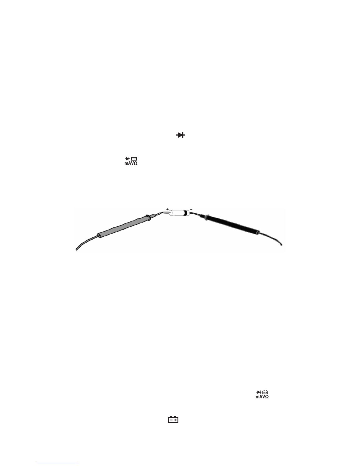
(3) Touch the red test lead to the anode (positive terminal) of the diode
to be tested and the black test lead to its cathode (negative
terminal), as shown below.
(4) Read the diode’s forward bias voltage drop on the display. A silicon
diode typically has a forward voltage drop of 0.7V. A germanium
diode typically has a forward voltage drop of 0.3V. A 0V reading in
both directions indicates a shorted diode. A readout of .OL means
either of two things: the leads are reversed, or the diode is
defective. Reverse the leads. If this still produces a readout of .OL,
the diode is defective and should be replaced.
CHECKING BATTERY VOLTAGE
Warning
To avoid possible electrical shock or damage to the meter, do not
apply a voltage greater than 250V between the meter’s and
COM jacks.
(1) Turn the rotary switch to the position corresponding to the
nominal voltage of the battery to be tested (12V, 9V or 1.5V).
10
RED TEST LEAD BLACK TEST LEAD
Table of contents
Other General Multimeter manuals


Popular Multimeter manuals by other brands


Gossen MetraWatt
Gossen MetraWatt METRAmax 6 operating instructions

PeakTech
PeakTech 4000 Procedure of calibration

YOKOGAWA
YOKOGAWA 90050B user manual

Gossen MetraWatt
Gossen MetraWatt METRALINE DMM16 operating instructions

Fluke
Fluke 8846A Programmer's manual

Tempo Communications
Tempo Communications MM200 instruction manual


