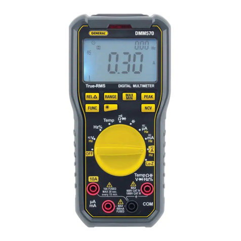
General DMM52FSG User manual

RUGGED SERVICE
MULTIMETERS
USER’S MANUAL
Please read this manual carefully and thoroughly before using this product.
DMM52FSG
DMM53FSG
DMM52&53FSG Manual_R1-FINAL-102114_Lay ut 1 11/21/14 12:02 PM Page 1

TABLE OF CONTENTS
Key Features . . . . . . . . . . . . . . . . . . . . . . . . . . . . . 2 –3
What’s in the Package . . . . . . . . . . . . . . . . . . . . . . . . 3
Product Overview . . . . . . . . . . . . . . . . . . . . . . . . . 3 –5
Safety Instructions . . . . . . . . . . . . . . . . . . . . . . . . 5 –6
Setup Instructions . . . . . . . . . . . . . . . . . . . . . . . . . . . 7
Install Battery . . . . . . . . . . . . . . . . . . . . . . . . . . . . . 7
Operating Instructions . . . . . . . . . . . . . . . . . . . . 7 – 13
General Instructions . . . . . . . . . . . . . . . . . . . . . . . . 7
Holding Readings . . . . . . . . . . . . . . . . . . . . . . . . . . 7
easuring AC or DC Current . . . . . . . . . . . . . . . 7 –9
easuring AC or DC Voltage . . . . . . . . . . . . . . . . . . 9
easuring Resistance . . . . . . . . . . . . . . . . . . . 9 – 10
easuring Capacitance (D 53FSG only)
. . 10 – 11
easuring Frequency (D 53FSG only) . . . . . . . 11
easuring Temperature (D 53FSG only) . . . . . 11
Checking for Continuity . . . . . . . . . . . . . . . . . . . . 12
Checking the Integrity of a Diode . . . . . . . . . 12 – 13
easuring Transistor hFE . . . . . . . . . . . . . . . . . . . 13
Specifications . . . . . . . . . . . . . . . . . . . . . . . . . . 13 – 16
Operating & aintenance Tips . . . . . . . . . . . . . . . . . 16
Warranty Information . . . . . . . . . . . . . . . . . . . . . . . . 17
Return for Repair Policy . . . . . . . . . . . . . . . . . . . . . . 18
KEY FEATURES
• 8 functions, 31 ranges (DMM52FS );
11 functions, 32 ranges (DMM53FS )
• Measures AC/DC voltage, AC/DC current, resistance,
bipolar transistor forward current gain (hFE)
• Also measures capacitance, frequency, temperature
using included “K” type bead thermocouple probe
(DMM53FS only)
2
DMM52&53FSG Manual_R1-FINAL-102114_Lay ut 1 11/21/14 12:02 PM Page 2

• 0 to 20μADC and 0 to 200μADC ranges (DMM52FS ) /
0 to 20μADC range (DMM53FS ) for measuring flame
rod current
• Checks continuity and diode integrity
• IP54 water/oil/dust protection
• 6.6 ft. (2m) drop-resistant
• ETL approved CAT III 600V safety rating
• Jumbo 3-1/2 digit (2000 count) LCD with
0.95 in. (24mm) high digits
• 25-minute Auto Power Off
• Powered by “9V” battery (not included)
• Low battery indication
• 1 year limited warranty
WHAT’S IN THE ACKAGE
The meter is supplied in a color box along with:
• A pair of 1000V/10A-rated double-insulated test leads
with banana plugs
• A “K” type bead thermocouple probe with two output
banana plugs at the end of separate wires (DMM53FS
only)
• A multi-function plug adaptor with two output banana
plugs 3/4 in. apart and holes for inserting the three
leads of a bipolar transistor
• This user’s manual
RODUCT OVERVIEW
Fig. 1 shows the labels and positions of the controls, LCD
and physical structures of the DMM52FS /DMM53FS .
Fig. 2 shows all possible indications on the LCD.
Familiarize yourself with the functions and meanings of
all controls, indications and connectors before moving on
to the Setup Instructions and Operating Instructions.
3
DMM52&53FSG Manual_R1-FINAL-102114_Lay ut 1 11/21/14 12:03 PM Page 3

Fig. 1. The controls, display and physical features of
the D 52FSG (left) and D 53FSG (right)
1) LCD 2) Power ON/OFF button
3) HOLD button 4) Rotary function switch
5) Input jacks 6) Battery compartment (on back)
7) Flip-up stand (on back)
Fig. 2. All possible display indications
Notes:
1) The icon appears as a safety reminder whenever the
rotary switch is in the 600VDC or 600VAC position.
2) The numbers 2, 20 and 200 at the bottom of the
display indicate the high end of the currently selected
measurement range.
3) The word HOLD indicates that the displayed value is a
held reading.
4
1
6
7
4
323
2
55
DMM52&53FSG Manual_R1-FINAL-102114_Lay ut 1 11/21/14 12:03 PM Page 4

4) A readout of 1. indicates a measurement greater than
the currently selected full-scale range (an overload).
Switch to the next-widest range.
SAFETY INSTRUCTIONS
Warning
To avoid possible electric shock or personal injury, and to
avoid damaging the meter or the equipment under test:
• Do not use the meter in any way not detailed in this
manual or the meter's safety features may be
compromised.
• Before using the meter, inspect the case.
Do not use the meter if it is damaged. Look for cracks
or missing plastic. Pay particular attention to the
insulation around the connectors.
•
WARNING
Inspect the test leads for damaged
insulation or exposed metal. Check the test leads for
continuity. Replace damaged test leads before using
the meter.
• Verify the meter’s operation by measuring a known
voltage. Do not use the meter if it operates abnormally.
Protection may be impaired. When in doubt, have the
meter serviced.
•
WARNING
Do not apply more than the rated voltage,
as marked on the meter, between the or
and
CO
jacks or between any other jack and ground.
Also do not input more than the rated current, as
marked on the meter, through the
10A,
or
jack.
•
WARNING
Do not measure voltages above 600V in
Category III installations.
•
WARNING
Do not attempt to measure voltage with
the rotary function switch in any position not in the in
any position not in the or section. Never
attempt to measure current with the rotary function
switch in any position not in the or section.
• Use caution when working with voltages above
42VACRMS, or 60VDC. These voltages pose a shock
hazard.
V
V
5
DMM52&53FSG Manual_R1-FINAL-102114_Lay ut 1 11/21/14 12:03 PM Page 5

•
WARNING
Do not operate the meter around
explosive gas, vapor, or dust.
•
WARNING
When using the test leads, keep your
fingers behind the finger guards. Do not touch the
metal probes of the test leads when making a
measurement.
• When making connections, connect the black (–) test
lead before connecting the red (+) test lead; when
disconnecting, disconnect the red (+) test lead before
disconnecting the black (–) test lead.
• Disconnect circuit power and discharge all high-
voltage capacitors before measuring/testing resistance,
continuity, diodes, or capacitance.
• Before measuring current, turn off power to the circuit
before connecting the meter.
• Do not operate the meter with the case (or part of the
case) removed.
• Use only (1) “9V” battery, properly installed in the
battery compartment, to power the meter. Do not use
rechargeable batteries.
• Replace the battery as soon as the low battery
indicator “ ” appears. Operated with a weak
battery, the meter might produce false readings that
could lead to electric shock and personal injury.
• Remove the test leads from the meter before opening
the meter case or battery compartment.
6
DMM52&53FSG Manual_R1-FINAL-102114_Lay ut 1 11/21/14 12:03 PM Page 6

SETU INSTRUCTIONS
INSTALL BATTERY
Turn the meter over to gain access to the battery
compartment. To open the compartment:
1) Use a small Phillips-head screwdriver to remove the
single screw at the top of the one-piece battery
compartment cover/flip-up stand.
2) Put the cover/stand aside.
3) Obtain a “9V” battery and plug it into the wired socket
inside the compartment. The terminals of the battery
and the socket mate in only one way, with the smaller
male terminal plugging into the larger female terminal.
4) Secure the battery compartment by replacing the
cover/stand and reinstalling and tightening the
Phillips-head screw.
O ERATING INSTRUCTIONS
GENERAL INSTRUCTIONS
All parameters except bipolar transistor forward current
gain (hFE) and temperature (DMM53FS only) are
measured through the included test leads. Measurements
of hFE and temperature are made using included
accessories. The specific operating instructions for each
parameter explain which jacks to plug the test leads or
an accessory into.
HOLDING READINGS
Pressing the HOLD button “freezes” any measurement on
the LCD and causes the word HOLD to appear at its left.
Pressing the button again releases the hold, removes the
word HOLD and resumes real-time measurements.
MEASURING AC OR DC CURRENT
Warning
Do not attempt to measure: 1) currents larger than
200mA through the jack DMM52FS ) or jack
(DMM53FS ); 2) currents larger than 10A through the
10A jack; or 3) currents larger than 5A through the 10A
jack for more than 10 seconds at a time or for more than
7
DMM52&53FSG Manual_R1-FINAL-102114_Lay ut 1 11/21/14 12:03 PM Page 7

30 seconds every 15 minutes; pause 1 minute after each
measurement of such a large current.
(1) Remove power from the circuit to be tested and
discharge all high-voltage capacitors.
(2) Turn the rotary switch to one of the or
positions, depending on the type and amplitude of the
current you expect to encounter. If you are unsure
what type to expect, select one of the positions.
If you are unsure what amplitude to expect, select
the 10 position.
(3) Plug the black test lead into the black CO jack at the
bottom left of the front panel.
(4) Plug the red test lead into the red/yellow 10A jack,
red jack (DMM52FS ) or red jack
(DMM53FS ) on the front panel. Choose the 10A jack
if you have set the rotary switch to the 10 position,
and the or jack if you have set the rotary
switch to one of the or positions.
(5) Break the circuit and connect the test leads across
the break. Connect the red lead to the higher-voltage
side of the break and the black lead to the lower-
voltage side.
(6) Re-apply power to the circuit and observe the display.
If it shows 1., the current amplitude is beyond the
selected current range. If that is the case, move the
rotary switch to the next-widest position. When
measuring DC current, if the readout is a negative
value the leads are reversed, but the absolute value
represents a valid measurement of current amplitude.
(7) Remove power from the circuit and discharge all
high-voltage capacitors.
(8) Disconnect the test leads and restore the circuit to its
original condition by eliminating the break you made
in Step 5.
8
DMM52&53FSG Manual_R1-FINAL-102114_Lay ut 1 11/21/14 12:03 PM Page 8

Note:
eneral’s FX3000 Flex Clamp Adapter makes it possible
to measure the current carried by a thick or hard-to
reach conductor, a bundle of conductors, or a busbar
carrying up to 3000A. The accessory uses induction to
convert current readings to millivolt values that can be
displayed by the DMM52FS or DMM53FS . For more
information or to order, visit www.generaltools.com and
enter “FX3000” in the SEARCH box.
MEASURING AC OR DC VOLTAGE
Warning
Do not measure any AC or DC voltage higher than 600V.
Doing so may damage the meter’s internal circuitry.
(1) Turn the rotary switch to one of the or
positions, depending on the type and amplitude of
voltage you expect to encounter. If you are unsure
what type to expect, select one of the positions.
If you are unsure what amplitude to expect, select the
600 position.
(2) Plug the black test lead into the front-panel CO jack
and the red test lead into the (DMM52FS ) or
(DMM53FS ) jack.
(3) Touch the black test lead to the lower-potential point
of the circuit under test, and the red test lead to the
higher-potential point.
(4) Read the measured voltage on the display. If the
readout is 1., the voltage level is beyond the currently
selected range. If that is the case, move the rotary
switch to the next-widest position. When measuring
DC voltage, if the test leads are reversed a minus sign
will appear at the left of the readout.
MEASURING RESISTANCE
Warning
To avoid electrical shock or damage to the meter when
measuring resistance, turn off all power to the circuit and
discharge all high-voltage capacitors.
V
V
V
9
DMM52&53FSG Manual_R1-FINAL-102114_Lay ut 1 11/21/14 12:03 PM Page 9

(1) Turn the rotary switch to one of the Ω positions. If you
are unsure how much resistance you expect to
encounter, select the 200 position.
(2) Plug the black test lead into the front-panel COM jack
and the red test lead into the (DMM52FS ) or
(DMM53FS ) jack.
(3) Measure the resistance by touching the test leads to
the desired test points of the circuit or to the terminals
of a component, as shown below.
(4) Read the measured resistance on the display. If the
readout is 1., the resistance value is beyond the
currently selected range. If that is the case, move the
rotary switch to the next-widest position.
Note: The meter will take a few seconds to stabilize when
measuring resistances greater than 2MΩ.
MEASURING CAPACITANCE (DMM53FSG ONLY)
Warning
To avoid possible damage to the meter or other
equipment, turn off the power source and discharge all
high-voltage capacitors.
(1) Disconnect the capacitor from power.
(2) Short the capacitor’s terminals to discharge it.
(3) Disconnect any resistors between the terminals of the
capacitor.
(4) Turn the rotary switch to one of the positions,
depending on the amount of capacitance you expect
to encounter. If you are unsure how much to expect,
select the 100μFposition.
(5) Plug the black test lead into the front-panel CO jack
and the red test lead into the jack.
(6) Connect the test leads to the terminals of the
capacitor.
10
RED TEST LEAD BLACK TEST LEAD
DMM52&53FSG Manual_R1-FINAL-102114_Lay ut 1 11/21/14 12:03 PM Page 10

(7) Read the measured capacitance on the display. If the
readout is 1., the capacitance value is beyond the
currently selected range. If that is the case, move the
rotary switch to the next-widest position.
MEASURING FREQUENCY (DMM53FSG ONLY)
Warning
To avoid possible damage to the meter or other
equipment, do not measure the frequency of any voltage
greater than 250V.
(1) Turn the rotary switch to the Hz position.
(2) Plug the black test lead into the front-panel CO jack
and the red test lead into the jack.
(3) Touch the test leads to the voltage source or between
loads.
(4) Read the measured frequency on the display. If the
readout is 1., the frequency is higher than 20kHz.
MEASURING TEMPERATURE
(DMM53FSG ONLY)
Warning
To avoid possible damage to the meter or other
equipment, do not measure the temperature of any
component carrying a voltage of 60VDC or 24VACRMS.
To measure the temperature of a component:
(1) Turn the rotary switch to the Temp position. The LCD
will immediately display the ambient temperature in
degrees Fahrenheit.
(2) Plug the black plug of the included “K” type
thermocouple probe into the front-panel CO jack
and the red plug into the jack
(3) Attach the bead of the probe to the component, taking
care not to burn yourself if the component is hot.
(4) Read the measured temperature on the LCD. If the
readout is 1., the temperature is outside the
meter’s measurement range of -4° to 1832°F
(-20° to 1000°C). Be aware that the measurement
range of the included thermocouple is -40° to 500°F
(-40° to 260°C).
11
DMM52&53FSG Manual_R1-FINAL-102114_Lay ut 1 11/21/14 12:03 PM Page 11

CHECKING FOR CONTINUITY
Warning
To avoid possible damage to the meter or other
equipment, turn off the power source and discharge all
high-voltage capacitors.
(1) Turn the rotary switch to the (DMM52FS ) or
(DMM53FS ) position.
(2) Plug the black test lead into the front-panel COM jack
and the red test lead into the (DMM52FS ) or
(DMM53FS ) jack.
(3) Touch the test leads to any two points of the circuit.
The resistance between those two points will be
displayed. If the resistance is <50Ω, the beeper will
sound continuously. If there is no continuity (an open
circuit or a resistance greater than 50Ω) between the
two points, 1. will appear on the readout.
CHECKING THE INTEGRITY OF A DIODE
Warning
To avoid possible damage to the meter or other
equipment, turn off the power source and discharge all
high-voltage capacitors.
(1) Turn the rotary function switch to the
(DMM52FS ) or (DMM53FS ) position.
(2) Plug the black test lead into the front-panel COM jack
and the red test lead into the (DMM52FS ) or
(DMM53FS ) jack.
(3) Connect the red test lead to the anode (positive
terminal) of the diode to be tested and the black test
lead to its cathode (negative terminal), as shown
below.
12
RED TEST LEAD BLACK TEST LEAD
DMM52&53FSG Manual_R1-FINAL-102114_Lay ut 1 11/21/14 12:03 PM Page 12

(4) Read the diode’s forward bias voltage drop on the
display. A silicon diode typically has a forward bias
voltage of 0.7V. A germanium diode typically has a
forward bias voltage of 0.3V. A 0V reading in both
directions indicates a shorted diode. A readout of 1.
means either of two things: the leads are reversed, or
the diode is defective. Reverse the leads. If this still
produces a readout of 1., the diode is defective and
should be replaced.
MEASURING TRANSISTOR hFE
Warning
To avoid possible electrical shock or damage to the
meter, do not apply a voltage greater than 250V between
the meter’s (DMM52FS ) or (DMM53F ) jack and
ground.
(1) Turn the rotary switch to the hFE position.
(2) Insert the CO plug of the included multi-function
plug adaptor into the meter’s front-panel CO jack
and the + plug of the adaptor into the
(DMM52FS ) or (DMM53F )
jack.
(3) Observing the type of transistor and the labeling of its
leads, carefully insert the transistor’s collector, base
and emitter into the c, band eholes of the adaptor.
(4) Read the transistor’s forward current gain on the LCD.
S ECIFICATIONS
Parameter or Attribute Specification
Feature/
Function
AC voltage Measurement 0 to 200mV/2V/20V/200V/600V
ranges (DMM52FS );
0 to 2V/20V/200V/600V
(DMM53FS )
Measurement ±(0.8% of reading + 3 digits) in
accuracy 2V, 20V and 200V ranges;
±(1.2% of reading + 3 digits) in
200mV and 600V ranges
Maximum 100애V (DMM52FS ); 1mV
resolution (DMM53FS )
13
DMM52&53FSG Manual_R1-FINAL-102114_Lay ut 1 11/21/14 12:03 PM Page 13

Parameter or Attribute Specification
Feature/
Function
DC voltage Measurement 0 to 200mV/2V/20V/200V/600V
ranges
Measurement ±(0.5% of reading + 3 digits)
accuracy
Max resolution 100애V
AC current Measurement 0 to 20애A/200애A/2mA/20mA/
ranges 200mA/10A (DMM52FS );
0 to 20mA/200mA/10A
(DMM53FS )
Measurement ±(3% of reading + 5 digits) in
accuracy 10A range; ±(1.8% of reading
+ 5 digits) in 200mA range;
±(2% of reading + 5 digits) in
20애A range; ±(1% of reading
+ 5 digits) in other ranges
Maximum 0.01애A (DMM52FS ); 10애A
resolution (DMM53FS )
DC current Measurement
0 to 20애A/200애A/2mA/20mA/
ranges 200mA/10A (DMM52FS );
0 to 20μA/20mA/200mA/10A
(DMM53FS )
Measurement ±(2% of reading + 5 digits) in
accuracy 10A range; ±(1.5% of reading
+ 5 digits) in 200mA range;
±(2% of reading + 5 digits) in
20애A range; ±(0.8% of reading
+ 5 digits) in other ranges
Maximum 0.01애A
resolution
Resistance Measurement 0 to 200Ω/2kΩ/20kΩ/200kΩ/
ranges 2MΩ/20MΩ/200MΩ
Measurement ±(6% of reading + 10 digits) in
accuracy 200MΩ range; ±(1% of reading
+ 2 digits) in 20MΩ range;
±(0.8% of reading + 3 digits) in
200Ω range; ±(0.8% of reading
+ 2 digits) in other ranges
Maximum 0.01Ω
resolution
Frequency Measurement 0 to 20kHz
(DMM53FS range
only)
Measurement ±(2% of reading + 5 digits)/10Hz
accuracy/
resolution
14
DMM52&53FSG Manual_R1-FINAL-102114_Lay ut 1 11/21/14 12:03 PM Page 14

Parameter or Attribute Specification
Feature/
Function
Capacitance Measurement
0 to 2nF/20nF/200nF/2애F/100애F
(DMM53FS ranges
only)
Measurement ±(6% of reading+ 5 digits) in
accuracy 100애F range; ±(4% of reading+
3 digits) in other ranges
Max. resolution 1pF
Temperature Measurement -4° to 1832°F (-20° to 1000°C)
(DMM53FS range
only)
Measurement ±2% of reading/1°
accuracy/
resolution
Range/accuracy -40° to 500°F (-40° to 260°C)/
of included probe ±(2% of reading) + 2 digits)
Continuity Open circuit ~1mA/2.8V
current/voltage
Threshold ≤ 50Ω
Diode integrity Measurement range 0 to 1V
Open circuit current/voltage ~1mA/2.7V
hFE Measurement range 0 to 1000
Safety rating of meter CAT III 600V
Safety rating of test leads CAT III 1000V, CAT IV 600V with
tip caps on;
CAT II 1000V with tip caps off
Overvoltage protection 1000V
Input impedance 10MΩ
Sampling time 2X/sec
Impact resistance Drop from height of 2m (6.6 ft.)
Water/dust/oil protection level IP54
Display No. of digits 3-1/2
Maximum count 2000
Auto power off trigger 25 minutes of front-panel
inactivity
Operating temperature 32° to 104°F (0° to 40°C)
@<80%RH
Storage temperature 32° to 140°F (0° to 60°C)
@<80%RH w/out battery
Power source (1) “9V” battery (not included)
Dimensions 7.40 x 3.66 x 1.97 in.
(188 x 93 x 50mm)
Weight (including battery) 13.4 oz. (380g)
15
DMM52&53FSG Manual_R1-FINAL-102114_Lay ut 1 11/21/14 12:03 PM Page 15

Note: Accuracy values are stated for an operating
temperature between 64° and 82°F (18° and 28°C). All
accuracy specifications must be derated (increased) by
5.5% for each degree F of operating temperature outside
this range.
For example, an accuracy specification of ±3% between
64°F and 82°F would be derated to:
• ±3.165% (±3% + (3% x 5.5% x 1)) for operation at
63°F and 83°F (one degree outside the range)
• ±3.33% (±3% + (3% x 5.5% x 2)) for operation at
62°F and 84°F (two degrees outside the range)
• ±3.495% (±3% + (3% x 5.5% x 3)) for operation at
61°F and 85°F (three degrees outside the range) · etc.
O ERATING &
MAINTENANCE TI S
When the icon appears at the lower left of the LCD,
it’s time to replace the “9V” battery that powers the
meter (although measurements will remain valid for
several hours after the icon first appears). To replace the
battery, follow the instructions on p. 7.
Do not operate the DMM52FS /DMM53FS in the
presence of a flammable or explosive gas or near an arc
welder or induction heater.
After subjecting the meter to a large change in ambient
temperature, wait at least 30 minutes before making
measurements to guarantee the accuracy of readings.
Remove the battery when storing the meter or when you
do not expect to use it for an extended period of time
(months rather than weeks).
Do not disassemble the meter or immerse it in water.
16
DMM52&53FSG Manual_R1-FINAL-102114_Lay ut 1 11/21/14 12:03 PM Page 16

WARRANTY INFORMATION
eneral Tools & Instruments’ ( eneral’s) DMM52FS or
DMM53FS Rugged Service Multimeter is warranted to
the original purchaser to be free from defects in material
and workmanship for a period of one year. Subject to
certain restrictions, eneral will repair or replace this
instrument if, after examination, the company determines
it to be defective in material or workmanship. The
warranty period begins on the date of purchase. You are
encouraged to register your product online. eneral will
extend your warranty an additional 60 days if you register
at www.generaltools.com/ProductRegistry.
This warranty does not apply to damages that eneral
determines to be from an attempted repair by non-
authorized personnel or misuse, alterations, normal wear
and tear, or accidental damage. The defective unit must
be returned to eneral Tools & Instruments or to a
eneral-authorized service center, freight prepaid and
insured.
Acceptance of the exclusive repair and replacement
remedies described herein is a condition of the contract
for purchase of this product. In no event shall eneral be
liable for any incidental, special, consequential or
punitive damages, or for any cost, attorneys’ fees,
expenses, or losses alleged to be a consequence of
damage due to failure of, or defect in any product
including, but not limited to, any claims for loss of profits.
Register now at www.generaltools.com/ProductRegistry
to receive a 60-day extension to your warranty.
17
DMM52&53FSG Manual_R1-FINAL-102114_Lay ut 1 11/21/14 12:03 PM Page 17

RETURN FOR RE AIR OLICY
Every effort has been made to provide you with a reliable
product of superior quality. However, in the event your
instrument requires repair, please contact our Customer
Service to obtain an R A (Return oods Authorization)
number before forwarding the unit via prepaid freight to
the attention of our Service Center at this address:
eneral Tools & Instruments
80 White Street
New York, NY 10013
212-431-6100
Remember to include a copy of your proof of purchase,
your return address, and your phone number and/or e-
mail address.
18
DMM52&53FSG Manual_R1-FINAL-102114_Lay ut 1 11/21/14 12:03 PM Page 18

NOTES
______________________________________________
______________________________________________
______________________________________________
______________________________________________
______________________________________________
______________________________________________
______________________________________________
______________________________________________
______________________________________________
______________________________________________
______________________________________________
______________________________________________
______________________________________________
______________________________________________
______________________________________________
______________________________________________
______________________________________________
______________________________________________
______________________________________________
______________________________________________
______________________________________________
______________________________________________
______________________________________________
19
DMM52&53FSG Manual_R1-FINAL-102114_Lay ut 1 11/21/14 12:03 PM Page 19

GENERAL TOOLS & INSTRUMENTS
80 White Street
New York, NY 10013-3567
HONE (212) 431-6100
FAX (212) 431-6499
TOLL FREE (800) 697-8665
e-mail: [email protected]
www.generaltools.com
DMM52FSG, DMM53FSG User’s Manual
Specifications subject to change without notice
©2014 GENERAL OOLS & INS RUMEN S
NO ICE - WE ARE NO RESPONSIBLE FOR YPOGRAPHICAL ERRORS.
MAN# DMM52FSG, DMM53FSG
10/21/14
General Tools & Instruments
GeneralToolsNYC
DMM52&53FSG Manual_R1-FINAL-102114_Lay ut 1 11/21/14 12:03 PM Page 20
This manual suits for next models
1
Table of contents
Other General Multimeter manuals