manuals.online logo
Brands
  1. Home
  2. •
  3. Brands
  4. •
  5. Genesis
  6. •
  7. Speakers System
  8. •
  9. Genesis Genesis 2.2 Junior User manual

Genesis Genesis 2.2 Junior User manual

Other manuals for Genesis 2.2 Junior

2

This manual suits for next models

1

Other Genesis Speakers System manuals

Genesis Genesis 2.2 Junior User manual

Genesis

Genesis Genesis 2.2 Junior User manual

Genesis 350 User manual

Genesis

Genesis 350 User manual

Genesis 450XS User manual

Genesis

Genesis 450XS User manual

Genesis 1.1 User manual

Genesis

Genesis 1.1 User manual

Genesis Cobalt 300 User manual

Genesis

Genesis Cobalt 300 User manual

Genesis G6.1 User manual

Genesis

Genesis G6.1 User manual

Genesis Monitor 2 User manual

Genesis

Genesis Monitor 2 User manual

Genesis 350SE User manual

Genesis

Genesis 350SE User manual

Genesis G2.2 User manual

Genesis

Genesis G2.2 User manual

Genesis Genesis 201 User manual

Genesis

Genesis Genesis 201 User manual

Genesis Krypton 500 User manual

Genesis

Genesis Krypton 500 User manual

Genesis 1.2 User manual

Genesis

Genesis 1.2 User manual

Genesis Genesis 201 User manual

Genesis

Genesis Genesis 201 User manual

Popular Speakers System manuals by other brands

Monster MT-SB21 user manual

Monster

Monster MT-SB21 user manual

Monacor ESP-76AB/ WS manual

Monacor

Monacor ESP-76AB/ WS manual

Samsung HW-J430 user manual

Samsung

Samsung HW-J430 user manual

WILSON AUDIO WATT owner's manual

WILSON AUDIO

WILSON AUDIO WATT owner's manual

Hisense AX3125H user manual

Hisense

Hisense AX3125H user manual

EisSound KBSound iSelect user manual

EisSound

EisSound KBSound iSelect user manual

Boston Acoustics VRi793 manual

Boston Acoustics

Boston Acoustics VRi793 manual

Sven SPS-707bL Operation manual

Sven

Sven SPS-707bL Operation manual

Monacor DSM-26LAN instruction manual

Monacor

Monacor DSM-26LAN instruction manual

JVC CS-SR100 instructions

JVC

JVC CS-SR100 instructions

Samsung HW-C450 user manual

Samsung

Samsung HW-C450 user manual

TaoTronics evatronic ET-SK011 user guide

TaoTronics

TaoTronics evatronic ET-SK011 user guide

JVC HX-D7C instructions

JVC

JVC HX-D7C instructions

Pyle PBMSPG190 user manual

Pyle

Pyle PBMSPG190 user manual

Sven SPS-607 Operation manual

Sven

Sven SPS-607 Operation manual

iSP Technologies LT2 series owner's manual

iSP Technologies

iSP Technologies LT2 series owner's manual

Samsung Crystal Surround Air Track HW-F550 user manual

Samsung

Samsung Crystal Surround Air Track HW-F550 user manual

Bose Acoustimass 6 Series II owner's guide

Bose

Bose Acoustimass 6 Series II owner's guide

manuals.online logo
manuals.online logoBrands
  • About & Mission
  • Contact us
  • Privacy Policy
  • Terms and Conditions

Copyright 2025 Manuals.Online. All Rights Reserved.

Ver 2.1 November 2009
i
absolute fidelity
Owners Manual and Set-up Guide
Genesis 2.2 Loudspeaker System
Contents
SET-UP GUIDE 1
P
LANNING THE
P
LACEMENT
1
U
NPACKING
3
A
SSEMBLING THE
A
COUSTIC
S
USPENSION
4
T
HE
S
ERVO
-C
ONTROLLED
B
ASS
A
MPLIFIER
5
M
IDRANGE
/T
WEETER
C
ONNECTIONS
7
S
ERVO
-B
ASS
A
MPLIFIER
R
EMOTE
8
B
ASS
C
ONTROL
A
DJUSTMENTS
M
IDRANGE
/T
WEETER
C
ONTROLS
11
S
ERVO
-C
ONTROLLED
B
ASS
A
MPLIFIER
P
ROTECTION
12
A W
ORD ABOUT
F
INISH
12
TUNING THE SYSTEM 13
B
EGIN WITH THE BASS LEVEL
13
I
MAGING AND
S
OUNDSTAGE
14
P
HASE
C
ONTROL
15
F
URTHER ADJUSTMENTS
16
THE REFINEMENT STAGE 17
M
AKE
O
NE
C
HANGE
A
T
A T
IME
17
D
EFINING THE
S
OUNDSTAGE
18
A
PPROPRIATE
M
ID
-
BASS
/L
OW
-
BASS
B
ALANCE
18
R
OOM
T
REATMENT
1
M
ASTERING THE
R
EFINEMENTS OF THE SYSTEM
20
THE TECHNOLOGY 22
D
ESIGN
P
HILOSOPHY
22
T
HE
G
ENESIS
R
IBBON
T
WEETER
24
48
INCH MIDRANGE RIBBON
24
T
HE
S
ERVO
-
BASS
A
DVANTAGE
25
T
HE
W
OOFER
T
OWER
26
S
ERVO
-
CONTROLLED
A
MPLIFIER
27
T
HE
A
COUSTIC
S
USPENSION
28
S
PECIFICATIONS
2
Ver 2.1 November 2009
ii
absolute fidelity
A Message from Genesis
Congratulations! And Thank You!
You are now the owner of one of the finest loudspeaker systems in
the world! The Genesis 2.2 is the result of technologies developed
and refined over the past 4 years in constant production.
The G2.2 loudspeaker system was created for the music lover who
knows (almost) no compromise. It is designed to reproduce music
(and film) at live listening levels with virtually no restrictions on
dynamic range, frequency response, or imaging capabilities. This is
“
absolute fidelity™
”, the ability to reproduce the musical event
faithfully, as was intended by the performer or filmmaker.
However, the G2.2 is not meant to reproduce music at ear-splitting
levels. If you are looking for just LOUD, this is the wrong
loudspeaker. A Ferrari and a Caterpillar may have the same price
and horsepower, but they are very different vehicles and you
wouldn’t use your Ferrari to move a load of gravel.
Please read this Owners Manual and Set-up Guide to get the
maximum enjoyment out of your purchase. Also, if you have
access to the internet, please check back at our website often. The
address is www.genesisloudspeakers.com. We will put the latest
updates, tips and tricks, and support for our owners on our website
and in our newsletter.
Please write the purchase details of your Genesis 2.2 System
here for future reference. Remember, send in your registration
card to extend the limited warranty on your loudspeakers.
Bought from: ____________________________
____________________________
Date: ___________________________________
Serial Numbers:
Ver 2.1 November 2009
iii
absolute fidelity
This page intentionally left blank
Warranty Statement and Extended Registration Card
should be placed here
Ver 2.1 November 2009
1
absolute fidelity
Set-up Guide
Now that you have your new Genesis 2 loudspeaker system, we
realize that you can’t wait to hook it up and start the music!
However, this is a big, complex system and we want you to set it
up correctly and more importantly, safely. So, please read this set
up guide (even if your dealer is setting it up for you!) before you
proceed.
Planning t e Placement
Before you even have the loudspeakers delivered, it would be a
good idea to make a plan of where you will place them. You will
not need a huge room, but at a minimum the room should be about
15 feet (5m) wide where the speakers will be placed. You should
have a minimum of at least 6 feet (2m) of space behind the
speakers. The listening position should be a minimum of 1 feet
(3m) from the front of the midrange ribbon to allow for proper
integration of the drivers.
In a typical placement, the midrange/tweeter wings will be placed so
that the two columns of tweeters are on the inside, and between six
feet to eight feet (2m to 2.6m) apart. The woofer towers are placed
behind and outside the wings with the column of woofers about 4 feet
Ver 2.1 November 2009
2
absolute fidelity
from the midrange ribbons. In order to allow for sufficient space from
the sidewalls, this dictates that the optimum room is at least 19 feet
(6m) wide.
Placing the woofer towers asymmetrical but equidistant from the
midrange/tweeter wings will result in better integration of the bass
frequencies to the room. Keep the side of the woofer towers no
less than 16 inches from the sidewall.
The suggestions here are typical in a minimum space. With a larger
room, it is possible (and optimal) to have a layout as shown below
with the midrange, tweeters and woofers equidistant from the
listening position. Still, the woofer towers should be placed
asymmetric in the room with the distances of the woofers from the
Ver 2.1 November 2009
3
absolute fidelity
nearest wall being different.
As the room will greatly influence the sound of your system, fine-
tuning adjustments in placement will be necessary. Every room will
be different, with doorways, furniture, closets, wall construction and
covering, etc. all making a significant impact on positioning.
Unpacking
The Genesis 2.2 system will arrive in a number of pieces. There
are four large wooden shipping crates, two containing the woofer
towers, two holding midrange/tweeter panels (or “wings”). There
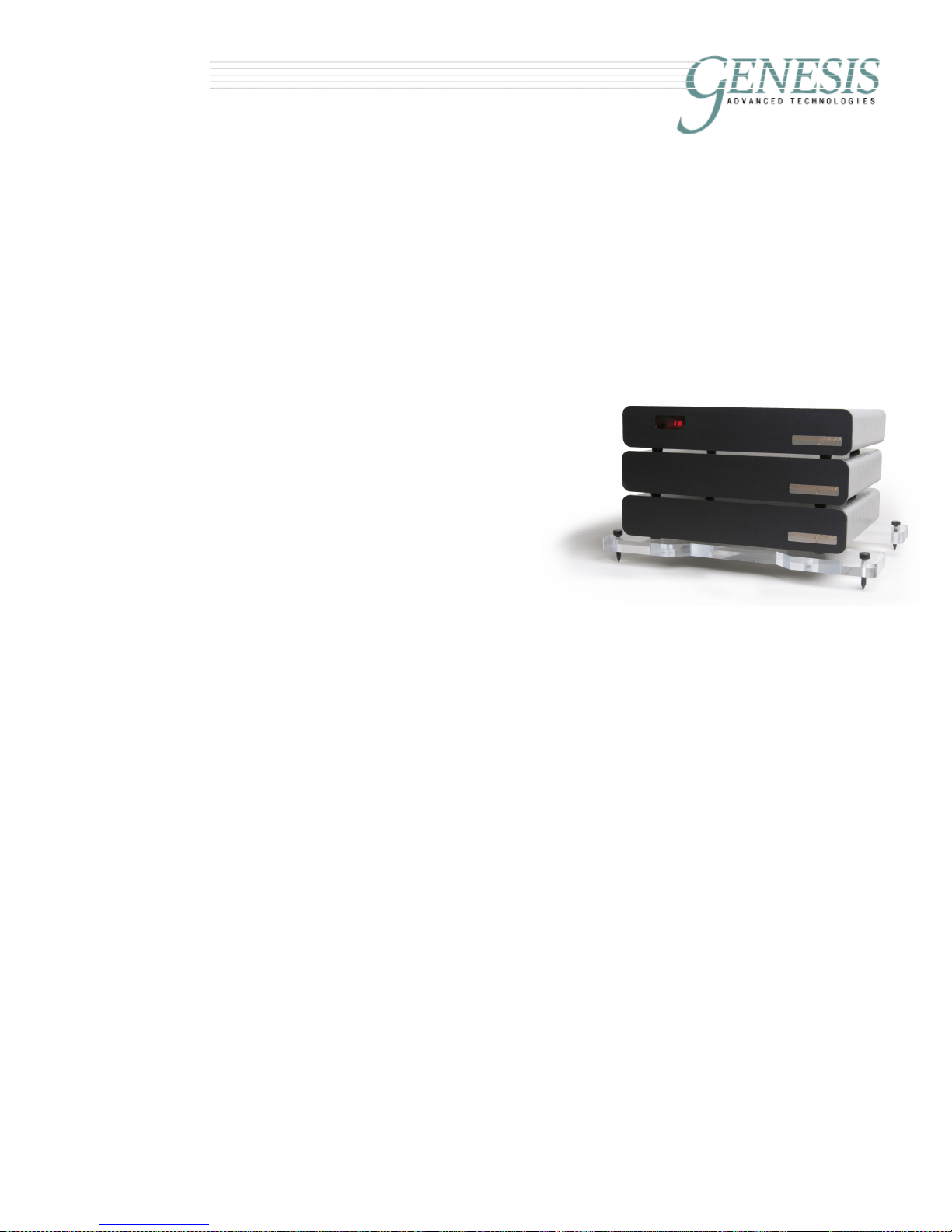
will also be a pallet of cardboard boxes holding the acoustic
suspension system, the various modules of the servo-controlled
bass amplifier, and a box containing the various cables. (There
could also be up to three more boxes if you have the optional
Maximum Dynamic Headroom Reservoir and power supply
upgrades to the servo-controlled bass amplifier.)
To remove the contents of all the crates, you will need help. The
G2.2 loudspeaker system with crates weigh a total of 1,4 lbs.
Each woofer tower weighs over 22 lbs, and each tweeter tower
weighs over 15 lbs and they have to be lifted out of the shipping
crates. We are not liable for damage (to either the speakers or
your backs!) during unpacking and setting up.
We suggest the use of a forklift to move these
crates around, and at least four strong people to
un-box and position the loudspeakers. In order to
remove the loudspeakers from the crates, the front
and top of the crates can be removed. This is
secured with screws – remove all exposed screws
except the ones marked with blue paint – and the
top and front can be lifted away.
With the top and front of the crate removed, each
wing and tower of the loudspeaker can be carefully
lifted and slid out of the crate. Before you put the
speaker up on its feet, it will be necessary to install
the acoustic suspension (next page).
After unpacking, we strongly suggest that the crates be dismantled,
flattened and safely stored away in a cool, dry place. They will be
needed should you relocate or move. It will be expensive to custom
Ver 2.1 November 2009
4
absolute fidelity
build crates strong enough to transport these loudspeakers without
damage.
Assembling t e Acoustic Suspension
A unique feature of the Genesis 2.2
loudspeaker system is the integration of an
acoustic suspension system for the
loudspeaker columns. This is an essential
feature of the cabinet structure – resulting in
lower coloration, better definition and rock-
solid imaging.
The suspension system comprises of a
suspension frame made of 1-inch of solid
cast acrylic, a set of Neoprene decoupling
shock absorbers, and a set of steel spikes.
Should you be placing the speakers on a hardwood floor or a floor
that would scratch easily, do not use “spike cups”. These defeat the
purpose of having a spike in the first place! Use a copper penny –
the weight of the speaker on the spike will create a depression in
the penny, and this point is what will efficiently transfer vibration to
the floorboards.
A couple of points to note during the assembly of the acoustic
suspension system:
1) The triangular “hole” in the suspension frame points to the
front of the speaker (towards the listener).
2) Do not over tighten the shock absorbers that are pre-
installed on the cabinet – finger tight is sufficient. A hex-key
(or allen wrench) is supplied to tighten the bolts holding the
suspension frame to the shock absorbers. Again, do not
over tighten these bolts.
3) The point of the spike should protrude through the
suspension frame only far enough to couple to the floor. If on
a concrete or marble floor, for example, 5mm or 1/5” is more
than sufficient. If you have your speakers on a 1/2" deep pile
carpet, then you will need to have the spike protrude about
3/4" so that the suspension frame clears the carpet.
4) If you need to move the loudspeaker after you have installed
the spikes, do not “walk” the speaker cabinet on the spikes –
retract the spikes first, shift the speakers, and then lower the
Acoustic Suspension under the
midrange/tweeter wings
Ver 2.1 November 2009
5
absolute fidelity
spikes again. This will avoid causing damage to the acoustic
suspension and to your floor.
5) While the acoustic suspension is designed for you to be able
to use the system on any surface, if you have very light and
resonant bare floorboards, you may need to place a heavy
slab of marble, slate, or granite under the loudspeaker to
avoid exciting the floor.
T e Servo-Controlled Bass Amplifier
The included remote-controlled
modular Servo-Controlled Bass
Amplifier powers the woofer
towers of the G2. There are
three modules, an acoustic
suspension (or amplifier stand)
plus a power supply unit and
numerous supplied cables in
the standard configuration.
The parts of the amplifier are:
1) The electronic crossover and Control Module with left
and right balanced inputs and two control outputs.
2) A pair of Control Interface Cables (CIC): these have
7-pin Neutrik™ connectors at each end.
3) A pair of Servo-Bass Interconnects (SBI) with XLR
connectors at one end and a pair of banana plugs (or
optionally spades) at the other end.
4) Two Servo-feedback Amplifier Modules with one
control input, and two Neutrik 5 -amp Speakon™
outputs.
5) One Acoustic Suspension system.
6) Two pairs of Servo-Bass Cables (SBC) with Neutrik
5 -amp Speakon™ plugs at each end.
7) A Power Transformer for each Amplifier Module with
two Neutrik™ 2 -amp PowerCon™ outlets.
8) A pair of Power Umbilicals with a Neutrik 2 -amp
Powercon plug at each end (one grey and one blue).
As an optional upgrade, comprising two Maximum Dynamic
Headroom Reservoirs and an additional Control Module is
available. This conveys additional macro- and micro-dynamic
Genesis 2 Servo-Controlled Bass Amplifier
Ver 2.1 November 2009
6
absolute fidelity
capabilities to the servo-bass system. Having the extra Control
Module also affords more fine tuning capabilities for the bass. This
is particularly important with asymmetric rooms. With this upgrade,
an additional Acoustic Suspension systems are supplied.
In the typical configuration, the Control Module, and two Servo-
feedback Amplifiers are placed in a stack between the midrange/
tweeter wings. The Power Transformers are placed behind the
stack. Using the supplied Power Umbilicals, connect the Power
Supply to the two Amplifier Modules.
A word of caution – the Neutrik PowerCon connectors used
for linking the power supply to the amplifiers are designed for
passing current. They are not designed to make/break current.
Hence be sure to connect the Power Umbilicals before you
connect the Power Supply to the wall outlet.
Using the supplied CIC, link the Control Module to each of the
Servo-feedback Amplifiers. One amplifier module is for the RIGHT
woofer tower and the other will be for the LEFT. This can be
determined by the last letter of the serial number. It does not matter
which CIC is used for the right channel and which is used for left.
However, one is marked with a red ring and the other is marked
with a white ring for convenience.
Use the SBC to connect the woofer
towers to the woofer amplifier. Each
end of the cable has a pair of 5 amp
twist-lock Neutrik™ Speakon™
connectors, and is clearly marked,
AMPLIFIER
or
SPEAKER
. It does not
matter which connector is used as
long as the correct amplifier module is
used for the left and right towers. It
does not matter which SBC is used for
the left or the right; however, one is
marked with
AMPLIFIER
or
SPEAKER
in
red lettering, and the other in white
lettering.
When you connect the woofer tower outputs pay close attention to
the way the connector works. It only goes in one way and you
cannot put it in wrong. However, you can fail to put it in all the way
Ver 2.1 November 2009
7
absolute fidelity
Servo-Bass Interconnects
parallels speaker cable inputs
or fail to lock it in place. Line up the alignment pins on the
connectors, push the plug in, and twist it clockwise until the lock
"clicks" in place to keep it there. By looking carefully, it will be
obvious as to how it works.
At the
AMPLIFIER
end of the servo-bass cable, you will find a male 1/8”
jack. The female end is on the chassis of the servo-bass amplifier
labelled GND. These jacks are used for grounding an internal shield
within the servo-bass cable. For the time being, leave this shield
disconnected. The shield ground should be used only when
necessary.
Midrange/Tweeter Connections
Next, connect the mid/tweeter
panels to your power amplifier
using a pair of high quality
loudspeaker cables (not
supplied) to the 5-way binding
posts. We recommend using
good quality spade
connectors for this job.
There are two ways to get the
music signal from your hifi
system to the Servo-Controlled Bass Amplifier to drive the woofers.
The first, and preferred way is to drive it using the output of the
power amplifier that is driving the midrange/ tweeter panels using
the supplied pair of Servo-Bass Interconnects.
The Servo-Bass Interconnect will be supplied with a pair of banana
plugs at one end, and an XLR balanced male plug at the other end.
The banana plugs will plug straight into the binding posts of the G2
midrange/tweeter tower inputs when you are using speaker cables
with spade connectors. If your speaker cables use banana plugs,
you can order spade connectors with the SBI at no extra charge
when you order your loudspeakers.
The XLR connector contains a specially developed internal
balancing circuit that enables the power amplifier to drive the
balanced input of the servo amplifier. Because of the extremely
high impedance of the balancing circuit, the parallel connection
places absolutely no stress on the power amplifier. Do not use any
other interconnect cable for this purpose as the high level output