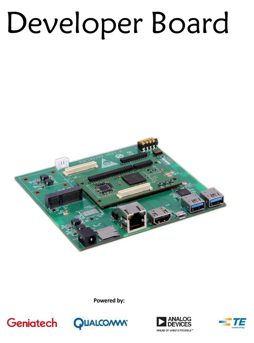
Geniatech DeveloperBoard4-IoT User manual

2
Contents
1
Introduction
....................................................................................................................................................................3
2
What’s
in
the
Box
.............................................................................................................................................................5
3
DB4 IOT Overview
............................................................................................................................................................6
3.1
Processor
..............................................................................................................................................................6
3.2
Memory
................................................................................................................................................................6
3.3
WiFi/BT
.................................................................................................................................................................6
3.4
Camera
Interfaces
..................................................................................................................................................6
3.5
USB
Device port......................................................................................................................................................6
3.6
DC-power
................................................................................................................................................................6
3.7
UART
......................................................................................................................................................................6
3.8
JTAG
........................................................................................................................................................................6
3.9
System
and
user
LEDs
...............................................................................................................................................7
3.10
RTC Battery
...........................................................................................................................................................7
3.11
Expansion
Connector
.............................................................................................................................................7
4 Low speed Expansion connector
..........................................................................................................................................8
4.1
UART
{0/1}
...........................................................................................................................................................10
4.2
I2C
{0/1}
..............................................................................................................................................................10
4.3
GPIO
{A-L}
...........................................................................................................................................................10
4.4
SPI
0
...................................................................................................................................................................10
4.5
PCM/I2S
..............................................................................................................................................................10
4.6
Power
and
Reset
..................................................................................................................................................11
4.7
Power
Supplies
....................................................................................................................................................11
5
Status
LED’s
....................................................................................................................................................................12
5.1
User
LED
1-4
..........................................................................................................................................................12
5.2
Bluetooth
status
....................................................................................................................................................12
5.3
WiFi
status
............................................................................................................................................................12
Downloaded from Arrow.com.Downloaded from Arrow.com.

3
1
Introduction
The Developer Board 4 IOT (hereinafter referred to as DB4 IOT) is a 96Boards compliant community board based on Qualcomm®
Snapdragon 400 series of SoC’s.
The following table lists its key features:
Processor
Snapdragon 410E quad core ARM® Cortex® A53 (64bit, 1.2GHz)
Qualcomm® Adreno™306 GPU
Memory/
Storage
1GB or 2GB LPDDR3 533MHz
8GB or 16GB eMMC V4.5
SD 3.0 (UHS-I)
Camera Support
1x MIPI-CSI: 1x 2-lane, up to 8MP
Connectivity
WLAN 802.11 b/g/n 2.4GHz
Bluetooth 4.1
One USB 2.0 micro B (device mode only)
On-board BT and WLAN antenna
I/O Interfaces
One 40-pin Low Speed (LS) expansion connector
•UARTx2, SPI, I2S, I2C x2, GPIO x12, DC power
User Interface
6 LED indicators
•4 - user controllable
•2 - for BT、WLAN
External Storage
1x Micro SD socket
OS-support
Android 5.1 ; Linux based on Debian ; Windows 10 IoT core;
Power,
Mechanical and
Environmental
Power: +12V
Dimensions: 35x60mm
Operating Temp: -25°C to +85°C
RoHS and Reach compliant
Downloaded from Arrow.com.Downloaded from Arrow.com.Downloaded from Arrow.com.

4
1.1
Board
overview
1.
lpddr3/eMMC
2.
APQ8016E Snapdragon Processor
3.
Power Management PMIC
4.
Camera Connector for MIPI CSI
5.
MicroUSB 2.0
6.
Boot Switches
7.
WLAN/Bluetooth IC
8.
WLAN/Bluetooth Antenna(optional)
9.
WLAN/Bluetooth Antenna
10.
User LED’s 1-4 and Bluetooth/WLAN LED’s
11.
Low Speed Expansion Connector
12.
Crypto Memory IC
13.
MicroSD card
Downloaded from Arrow.com.Downloaded from Arrow.com.Downloaded from Arrow.com.Downloaded from Arrow.com.

6
3
DB4-IOT Overview
3.1
Processor
The Snapdragon 410E APQ8016 is a quad 64-bit ARM Cortex-A53 MPcore Harvard Superscalar core, supports both LP-DDR2
/ LP-DDR3 SDRAM interface, Hexagon QDSP6, 13.5 MP camera input support, Adreno 306 GPU, 1080p video
encode/decode, gpsOneGen 8C with GLONASS, Bluetooth 4.1, OpenGL ES 3.0, DirectX, OpenCL, Renderscript Compute,
FlexRender support.
3.2
Memory
The DB4 IOT uses a single embedded Multi Chip Package (eMCP) dual function LPDDR3/eMMC memory solution. The installed
chip provides 16Bbyte of solid state storage and 2GBof LPDDR3.
•The LPDDR3 is a 32bit width bus implementation interfacing directly to the APQ8016 build-in LPDDR controller.
The maximum DDR clock is 533Mhz
•The eMMC is an 8bit implementation interfacing with APQ8016 SDC1 interface supporting eMMC 4.5
specifications.
3.3
WiFi/BT
The DB4 IOT deployed Qualcomm’s RF chip WCN3620 (U5) solution that integrates three different wireless connectivity
technologies into a single device, the interfaces are:
•WLAN compliant with IEEE 802.11 b/g/n specifications
•Bluetooth compliant with the BT specifications version 4.1 (BR/EDT + BLE)
3.4
Camera
Interfaces
The DB4 IOT implements one camera interfaces, with a 2-lane MIPI_CSI interface.
3.5
USB
Device port
The DB4 IOT implements a USB device port. The port is located at J4, a MicroUSB type B(device mode only).
3.6
DC-power
The DB4 IOT provide 2 ways of power to the board:
•An 6.5V to 18V power from the SYS_DCIN pins on the Low Speed Expansion Connector
•A 5V from USB Type C port (J4)
3.7
UART
The DB4 IOT has UART test pads(TP24,TP25,TP26) for reserved usage.
3.8
JTAG
The DB4 IOT has JTAG test pads(TP8-TP16) for reserved usage.
Downloaded from Arrow.com.Downloaded from Arrow.com.Downloaded from Arrow.com.Downloaded from Arrow.com.Downloaded from Arrow.com.Downloaded from Arrow.com.

7
3.9
System
and
user
LEDs
The DB4 IOT has six LEDs to be implemented on the board.
Two activity
LEDs:
•WiFi activity LED –DB4 IOT drives this Yellow LED via MPP_2, an IO from the PMIC.
•BT activity LED –DB4 IOT drives this Blue LED via MPP_3, an IO from the PMIC.
Four
User-LED’s:
The four user LEDs are surface mount Green in
0603 size located next to the two USB type A connector and labeled ‘USER
LEDS 4 3 2 1’. The DB4 IOT drives two LEDs from the SoC GPIO, APQ GPIO_21 and APQ GPIO_120. The other two User
LEDs are driven by the PMIC via PM GPIO_1 and PM GPIO_2.
3.10
RTC Battery (optional)
The DB4 IOT can carry and manage RTC / Battery for Real-Time Clock application.
3.11
Expansion
Connector
The DB4 IOT has one Low Speed Expansion Connector and section 4.0 for detailed information regarding the Low Speed
Expansion Connector.
Downloaded from Arrow.com.Downloaded from Arrow.com.Downloaded from Arrow.com.Downloaded from Arrow.com.Downloaded from Arrow.com.Downloaded from Arrow.com.Downloaded from Arrow.com.

8
4 Low speed Expansion Connector
The following tables show the Low Speed Expansion Connector pin out:
PIN
DB4 Signals
Note
1
3
5
7
9
11
13
15
17
19
21
23
25
27
29
31
33
35
37
39
GND
UART0_CTS_N (APQ GPIO_2)
UART0_TX (APQ GPIO_0)
UART0_RX (APQ GPIO_1)
UART0_RTS_N (APQ GPIO_3)
UART1_TX (APQ GPIO_4)
UART1_RX (APQ GPIO_5)
I2C0_SCL (APQ GPIO_7)
I2C0_SDA (APQ GPIO_6)
I2C1_SCL (APQ GPIO_23)
I2C1_SDA (APQ GPIO_22)
LS_EXP_GPIO_A (APQ GPIO_36) (APQ INT)
LS_EXP_GPIO_C (APQ GPIO_13) (TS_INT_N)
LS_EXP_GPIO_E (APQ GPIO_115) (GYRO_ACCL_INT_N)
LS_EXP_GPIO_G (APQ GPIO_24) (DSI_VSYNC)
LS_EXP_GPIO_I (APQ GPIO_35) (CSI0_RST)
LS_EXP_GPIO_K (APQ GPIO_28) (CSI1_RST)
LS_EXP_1P8
SYS_5P0
GND
Downloaded from Arrow.com.Downloaded from Arrow.com.Downloaded from Arrow.com.Downloaded from Arrow.com.Downloaded from Arrow.com.Downloaded from Arrow.com.Downloaded from Arrow.com.Downloaded from Arrow.com.

9
PIN
DB4 Signals
Note
2
4
6
8
10 GND GND
12
14
16
18
20
22
24
26
28
30
32
34
36
38
40
GND
PHONE_ON_N
PM_RESIN_N
SPI0_CLK (APQ GPIO_19)
SPI0_MISO (APQ GPIO_17)
SPI0_CS_N (APQ GPIO_18)
SPI0_MOSI (APQ GPIO_16)
LS_EXP_MI2S_WS (APQ GPIO_110)
LS_EXP_MI2S_SCK (APQ GPIO_113) (ALPS_INT)
LS_EXP_MI2S_DATA0 (APQ GPIO_114)
N.C.
LS_EXP_GPIO_B (APQ GPIO_12) (TS_RST_N)
LS_EXP_GPIO_D (APQ GPIO_69) (MAG_INT)
LS_EXP_GPIO_F (PM_MPP_4) (DSI_BLCTRL))
LS_EXP_GPIO_H (APQ GPIO_25) (DSI_RST)
LS_EXP_GPIO_J (APQ GPIO_34) (CSI0_PWDN)
LS_EXP_GPIO_L (APQ GPIO_33) (CSI1_PWDN)
SYS_DCIN
SYS_DCIN
GND
I2S
only
supports
audio
out
Borrowed
GPIO
from
PMIC
Downloaded from Arrow.com.Downloaded from Arrow.com.Downloaded from Arrow.com.Downloaded from Arrow.com.Downloaded from Arrow.com.Downloaded from Arrow.com.Downloaded from Arrow.com.Downloaded from Arrow.com.Downloaded from Arrow.com.

10
4.1
UART
{0/1}
The 96Boards specifications calls for a 4-wire UART implementation, UART0 and an optimal second 2-wire UART, UART1 on
the Low Speed Expansion Connector.
The DB4 IOT implements UART0 as a 4-wire UART that connects directly to the APQ8016 SoC. These signals are driven
at 1.8V.
The DB4 IOT implements UART1 as a 2-wire UART that connects directly to the APQ8016 SoC. These signals are driven
at 1.8V.
4.2
I2C
{0/1}
The 96Boards specification calls for two I2C interfaces to be implemented on the Low Speed Expansion Connector.
The DB4 IOT implements both interfaces, I2C0 and I2C1 that connects directly to the APQ8016SoC. A 2K resistor is
provided as pull-up for each of the I2C lines per the I2C specifications, these pull-ups are connected to the 1.8V voltage
rail.
4.3
GPIO
{A-L}
The 96Boards specifications calls for 12 GPIO lines to be implemented on the Low Speed Expansion Connector.
Some of
these GPIOs may support alternate functions for DSI/CSI control
The DB4 IOT implements this requirement.
11 GPIOs are routed to the APQ8016 SoC and one GPIO is connected to the
on-board PMIC.
•GPIO A - Connects to GPIO_36 of APQ8016 SoC, can serves as AQP_INT supporting the 96Boards requirements to
create a wake-up event for the SoC. It is a 1.8V signal
•GPIO B - Connects to GPIO_12 of APQ8016 SoC. It is a 1.8V signal
•GPIO C - Connects to GPIO_13 of APQ8016 SoC. It is a 1.8V signal. Can be configured to be an IRQ line
•GPIO D - Connects to GPIO_69 of APQ8016 SoC. It is a 1.8V signal. Can be configured to be an IRQ line
•GPIO E - Connects to GPIO_115 of APQ8016 SoC. It is a 1.8V signal. Can be configured to be an IRQ line
•GPIO F - Connects to MPP_4 of PM8916 PMIC. It is a 1.8V signal. Can be configured to be the DSI backlight control
•GPIO G - Connects to GPIO_24 of APQ8016 SoC. It is a 1.8V signal. Can be configured to be DSI VSYNC signal.
•GPIO H - Connects to GPIO_25 of APQ8016 SoC. It is a 1.8V signal. Can be configured to be a DSI_RST signal.
•GPIO I - Connects to GPIO_35 of APQ8016 SoC. It is a 1.8V signal. Can be configured to be a CSI0_RST signal.
•GPIO J - Connects to GPIO_34 of APQ8016 SoC. It is a 1.8V signal. Can be configured to be a CSI0_PWDN signal.
•GPIO K - Connects to GPIO_28 of APQ8016 SoC. It is a 1.8V signal. Can be configured to be a CSI1_RST signal.
•GPIO L - Connects to GPIO_33 of APQ8016 SoC. It is a 1.8V signal. Can be configured to be a CSI1_PWDN signal.
4.4
SPI
0
The 96Boards specification calls for one SPI bus master to be provided on the Low Speed Expansion Connector.
The DB4 IOT implements a full SPI master with 4 wires, CLK, CS, MOSI and MISO all connect directly to the APQ8016
SoC. These signals are driven at 1.8V.
4.5
PCM/I2S
The 96Boards specification calls for one PCM/I2S bus to be provided on the Low Speed Expansion Connector. The CLK, FS
and DO signals are required while the DI is optional.
The DB4 IOT implements a PCM/I2S with 3 wires, CLK, FS and DO, the optional DI signal is not implemented on the DB4 IOT
board.
The I2S signals are connected directly to the APQ8016 SoC. These signals are driven at 1.8V.
Downloaded from Arrow.com.Downloaded from Arrow.com.Downloaded from Arrow.com.Downloaded from Arrow.com.Downloaded from Arrow.com.Downloaded from Arrow.com.Downloaded from Arrow.com.Downloaded from Arrow.com.Downloaded from Arrow.com.Downloaded from Arrow.com.

11
4.6
Power
and
Reset
The 96Boards specification calls for a signal on the Low Speed Expansion Connector that can power on/off the board and a
signal that serves as a board reset signal.
The DB4 IOT routes the PWR_BTN_N (named PHONE_ON_N on DB4 IOT schematic) signal to the KYPDPWR_N pin of the
PM8916 PMIC. This signal is driven by S2 as well, the on-board power on push-button switch.
Please note that the push
button only provides an On/Sleep function and not OFF functionality.
A mezzanine implementation of this signals should not drive it with any voltage, the only allowed operation is to force it to
GND to start the board from a sleep mode. A board shutdown will occur when this signal is held to ground for more than
15 seconds (based on the current Android release).
The DB4 IOT routes the RST_BTN_N (named PM_RESIN_N on DB4 IOT schematic) signal to the RESIN_N pin of the PM8916
PMIC. This signal is driven by S4, the on-board reset switch. This signals is a dual purpose, any press lasting less than 10 seconds
serves as Volume Down or Zoom out, a press longer than 10 seconds will reset the board.
4.7
Power
Supplies
The 96Boards specification calls for three power rails to be present on the Low Speed Expansion Connector:
•+1.8V : Max of 100mA
•+5V : Able to provide a minimum of 5W of power (1A).
•SYS_DCIN
: 9-18V input with enough current to support all the board functions or the output DCIN from on-
board DC Connector able to provide a minimum of 7W of power.
The DB4 IOT supports these requirements as follows:
+1.8V : Driven by two PMIC LDOs, LDO15 and LDO16, each can provide 55mA. The PM8916 allows connecting the two
LDOs in parallel to provide 110mA on a 1.8V rail which meets the 96Boards requirement.
+5V : Driven by the 4A 5.0V buck switcher (U13). This buck switcher powers both USB limit current devices (each at
1.18A max).
The remaining capacity provides a max current of 1.64A to the Low Speed Expansion Connector, for a total of
8.2W which meets the 96Boards requirements.
SYS_DCIN: Can serves as the board’s main power source or can receive power from the board.
Downloaded from Arrow.com.Downloaded from Arrow.com.Downloaded from Arrow.com.Downloaded from Arrow.com.Downloaded from Arrow.com.Downloaded from Arrow.com.Downloaded from Arrow.com.Downloaded from Arrow.com.Downloaded from Arrow.com.Downloaded from Arrow.com.Downloaded from Arrow.com.

12
5
Status
LED’s
There are two status LEDs and four User LEDs on the DB4 IOT. The Status LEDs report the status of the Bluetooth and
Wi-Fi devices onboard. The user LEDs are driven by the SoC directly.
5.1
User
LED
1-4
The four user LEDs are surface mount Green LED, 0603 size, located next to the two USB type A connector and labeled
‘USER LEDS 4 3 2 1’.
5.2
Bluetooth
status
The BT LED on the DB4 IOT is located next to the USBOTG connector; this LED reflects the status of the Bluetooth
device.
5.3
WiFi
status
The WIFI LED on the DB4 IOT is located beside the BT LED, this LED reflects the status of the Wi-Fi device
Downloaded from Arrow.com.Downloaded from Arrow.com.Downloaded from Arrow.com.Downloaded from Arrow.com.Downloaded from Arrow.com.Downloaded from Arrow.com.Downloaded from Arrow.com.Downloaded from Arrow.com.Downloaded from Arrow.com.Downloaded from Arrow.com.Downloaded from Arrow.com.Downloaded from Arrow.com.

13
6 Boot configuration
There is a Dip Switch marked S6 located at the top side of the DB4. For normal operation the switched need to be set to the
‘off’ position.
When set to ‘on’ position, will force boot over USB connection with a PC. This is only required for eMMC boot image upgrade.
Downloaded from Arrow.com.Downloaded from Arrow.com.Downloaded from Arrow.com.Downloaded from Arrow.com.Downloaded from Arrow.com.Downloaded from Arrow.com.Downloaded from Arrow.com.Downloaded from Arrow.com.Downloaded from Arrow.com.Downloaded from Arrow.com.Downloaded from Arrow.com.Downloaded from Arrow.com.Downloaded from Arrow.com.
This manual suits for next models
1
Table of contents
Other Geniatech Motherboard manuals

Geniatech
Geniatech DB8 User manual

Geniatech
Geniatech XPI-3288 User manual

Geniatech
Geniatech RS-G2L100&RS-V2L100 Installation manual

Geniatech
Geniatech XPI-3128 User manual

Geniatech
Geniatech RK3399 User manual

Geniatech
Geniatech DB202 User manual

Geniatech
Geniatech DB-G2L-V2 User manual

Geniatech
Geniatech Dragon Board3 User manual

Geniatech
Geniatech XPI-S905X2 User manual

Geniatech
Geniatech XPI-S905X3 User manual