Geniatech DB202 User manual

Room 02-04, 10/F, Block A, Building 8, Shenzhen International Innovation Valley, Dashi Road, Nanshan District, Shenzhen, Guangdong, China
Emai: support@geniatech.com Tel: (+ 86) 755 86028588
Documentation
This development test instruction mainly describes the test points, test steps, and environmental construction involved
in the DB20x project test.
Website: www.geniatech.com
Address: Room 02-04, 10 / F, Block A, Building 8, Shenzhen International Innovation Valley, Dashi Road, Nanshan District,
Shenzhen, Guangdong,China.
REVISION HISTORY
No.
Chang cause
Chang version
Chang person
Chang DATA
Remark
1
Creating documentation
V1.0
WJ
2022-11-22
2
Modify RS232 not available
V1.01
MK
2023-04-13

Room 02-04, 10/F, Block A, Building 8, Shenzhen International Innovation Valley, Dashi Road, Nanshan District, Shenzhen, Guangdong, China
Emai: support@geniatech.com Tel: (+ 86) 755 86028588
CONTENTS
1. General Description .............................................................................................................................................................1
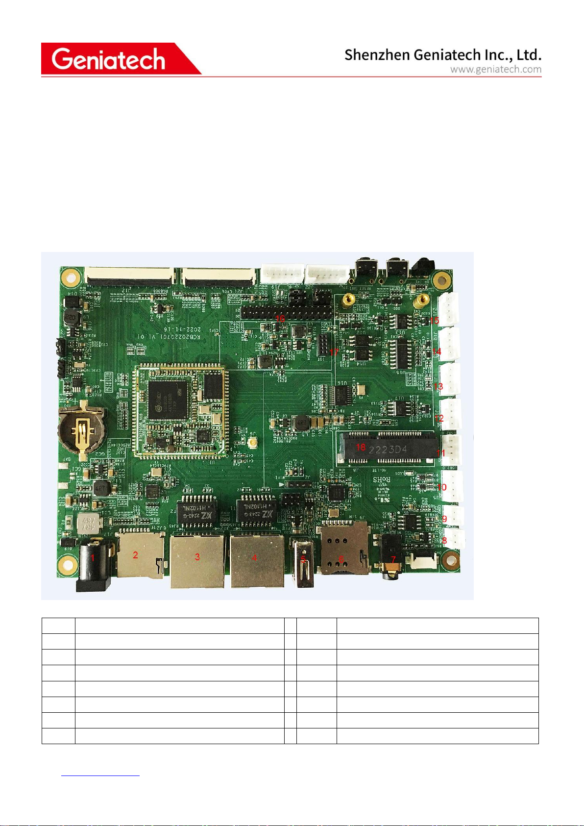
2. Product pictures .................................................................................................................................................................. 1
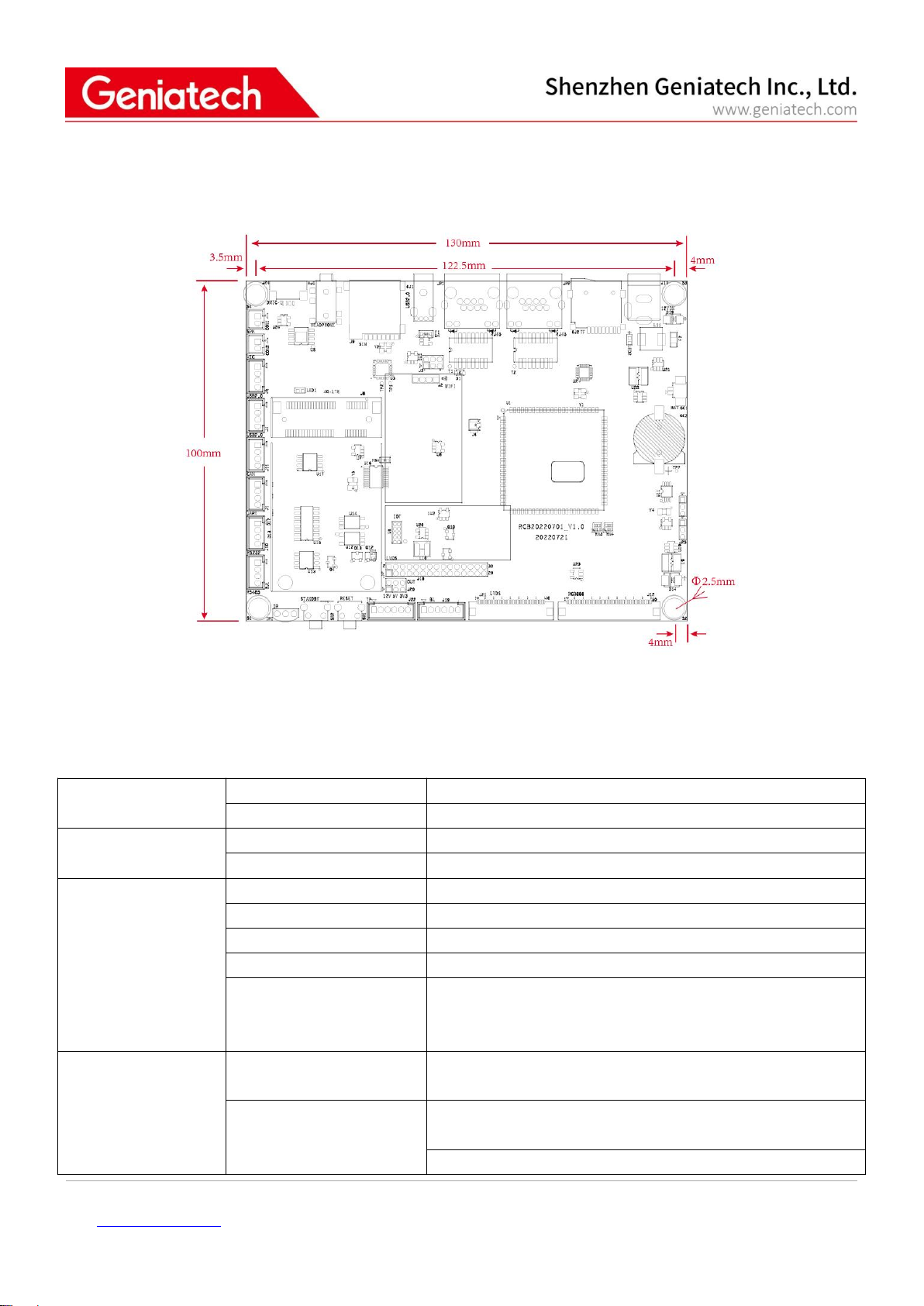
3.Board view ............................................................................................................................................................................2
4.Features ................................................................................................................................................................................ 2
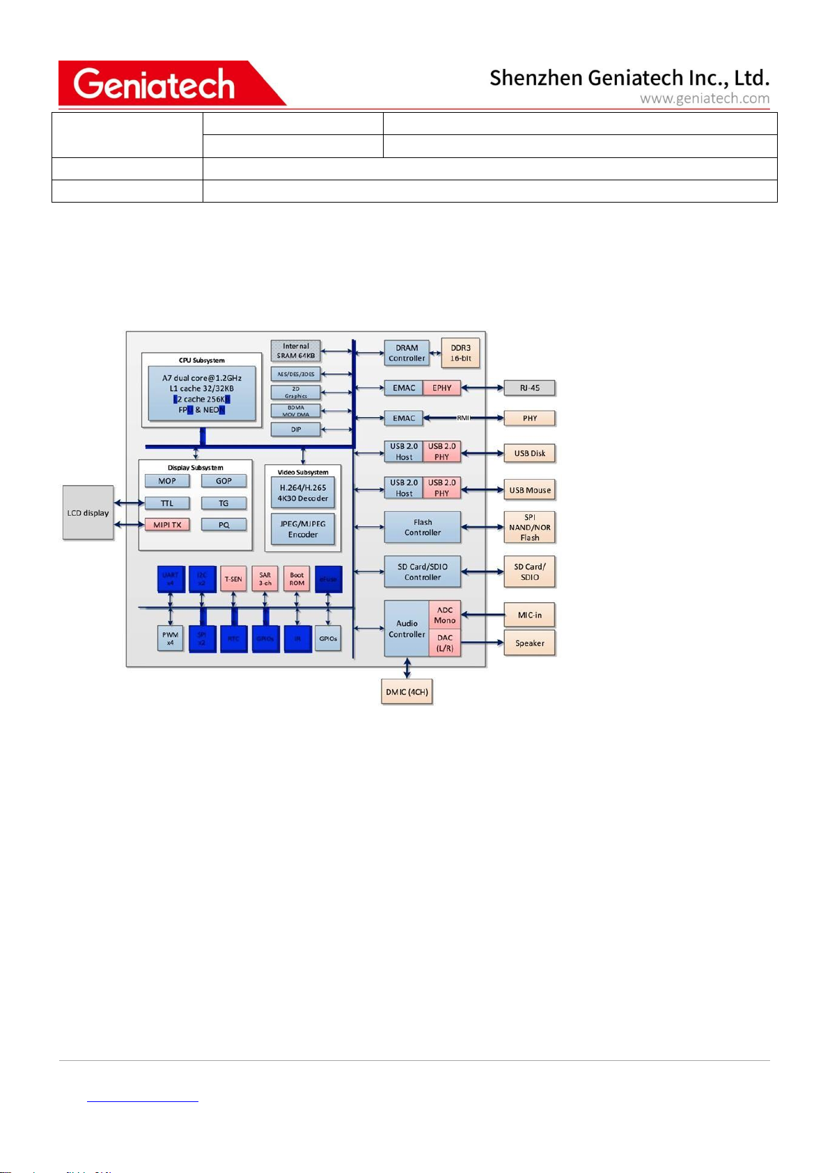
5.Sigmastar SSD20x Diagram ...................................................................................................................................................4
6.Support Formats ...................................................................................................................................................................4
7.Extension GPIO definition .................................................................................................................................................... 5
8.Functional Testing .................................................................................................................................................................6
8.1 Hardware Interface Diagram .....................................................................................................................................6
8.2 Test Preparation:.................................................................................................................................................... 7
8.3 WIFI Test .................................................................................................................................................................... 8
8.4 Ethernet Test........................................................................................................................................................... 10
8.5 TF Card Test............................................................................................................................................................. 11
8.6 Headset,Speaker,Microphone(headset mic and 2 Pin mic) ....................................................................................12
8.7 LVDS 7" Screen & Touch .......................................................................................................................................... 14
8.8 RS485 Communication ............................................................................................................................................ 15
8.9 LTE Test .................................................................................................................................................................... 17
8.10 USB Port Test ......................................................................................................................................................... 18
8.11 GTIOT Interface Test .............................................................................................................................................. 20
9. Precautions for use ............................................................................................................................................................22

Room 02-04, 10/F, Block A, Building 8, Shenzhen International Innovation Valley, Dashi Road,
Nanshan District, Shenzhen, Guangdong, China
Emai: support@geniatech.com Tel: (+ 86) 755 86028588
1
1. General Description
SSD20X is a highly integrated SoC chip from Sigmastar. It based on arm architecture (A7 dual core 1.2 GHz, integrates
hardware H.264 / H.265 video decoder, built-in DDR, built-in 2 d graphics engine, support for TTL/MIPI display driver
interface, built-in Ethernet MAC and PHY, etc., mainly used in intelligent building indoor machine, smart home control,
small gateway, elevator floor indicator, the speech recognition application of household appliances, VOIP, coffee
machine and so on many scenes with screen display.
Sigmastar SSD201/SSD202 with ARM Cortex-A7 Dual Core up to 1.2GHz
128MB RAM for SoM202 (64MB RAM for SoM201),128MB/256MB Nand Flash
Two 10/100M Ethernet
Tiny Linux OS,1s boot time
Supports MIPI-DSI 4-lane interface. TTL supports the RGB666 or RGB888 format, and also supports the LVDS
interface, with a maximum resolution of 1920 x 1080 FHD 60fps
With rich interfaces such as I2C, UART, SPI, USB2.0, RMII, I2S(supports digital microphone array input), and others
Support stereo input and output
Support 8K/16K/48KHz sampling rate recording
Stable operation at 0 °C-80 °C working temperature for 7X24 hours
Designed for Commercial Application
2.Product pictures
Below pictures are for reference only:

Room 02-04, 10/F, Block A, Building 8, Shenzhen International Innovation Valley, Dashi Road,
Nanshan District, Shenzhen, Guangdong, China
Emai: support@geniatech.com Tel: (+ 86) 755 86028588
2
3.Board view
4.Features
CPU
Chip
SigmaStar SSD201/SSD202
CPU Frequency
ARM® Cortex-A7 dual core up to 1.2GHz
Storage
Internal Memory
SoM202:DDR3 128MB SoM201: DDR2 64MB
Internal Storage
1/2/4 bit SPI-NOR/SPI-NAND Flash 128MB/256MB/512MB
Network
2G/3G/4G/LTE
LTE for EU、LTE for AU、LTE for US(Optional)
Built-in WiFi
802.11 a/b/g/n
WiFi 2.4G Frequency Range
2.400~2.497GHz
USB WiFi
Can delete built-in WiFi module,use external USB WiFi module.
Ethernet port(LAN)
1*RJ45 10/100Mbps LAN(JP1) Default Ethernet port
1*RJ45 10/100Mbps (JP2),This network port is reused with the
RGB display interface, and resistance hopping is required
Display
MIPI DSI
4-lane with max. 1.5Gbps and output up to FHD 60fps
30Pin FPC 0.5
RGB
HD 60fps with RGB666
40Pin FPC 0.5
HD 60fps with RGB888 format

Room 02-04, 10/F, Block A, Building 8, Shenzhen International Innovation Valley, Dashi Road,
Nanshan District, Shenzhen, Guangdong, China
Emai: support@geniatech.com Tel: (+ 86) 755 86028588
3
50Pin FPC 0.5
LVDS
Compatible with VESA and JEIDA standard
Resolution Up to 1920x1080 60Hz or any other Resolution
whose Pixel Clk less than 200MHz
40Pin FPC 0.5
Compatible with VESA and JEIDA standard
Resolution Up to 1920x1080 60Hz or any other Resolution
whose Pixel Clk less than 200MHz
2*15Pin 2.0
LVDS voltage
12V/5V/3.3V selection
6Pin 2.0 ranking
Touch interface
Capacitive touch
6Pin2.0 ranking
6Pin FPC 0.5
I/O interface
USB2.0
USB-A 2.0 x 1
Two 4Pin 2.0 ranking
CAN
4Pin 2.0 ranking
RS232
4Pin 2.0 ranking
RS485
4Pin 2.0 ranking
UART
4Pin 2.0 ranking
Protocol
RS485
TIA485/EIA-485-A
-7~+12V
CAN
ISO11898-2:2016 and SAE J2284-1 to SAE J2284-5
ESD Protection(8kV IEC and HBM)
5Mbit/s
UART
IO level 3.3V
RS232
±5~±15V
Audio interface
AMIC
8K/16K/32K/48KHz sampling rate
DMIC
8K/16K/32K/48KHz sampling rate
1 x LINEOUT
8K/16K/32K/48KHz sampling rate
IR Interface
1 x IR input
NEC code value
Extended interface
LEDs
Power
SIM Slot
Micro SIM Card
SD Card
Micro SD Card
GTIoT
2*5P 1.27 socket
Debug
4P 2.0 ranking
Button
Reset,User-defined custom keys(Power Standby)
Power pack
Supply voltage
DC12V 2A (4.5V~18V)
DC Interface
Φ5.5/2.1mm
Energy
Within 3W( No display screen for reference only)
RTC&Watchdog
3V
Environment
Operating temperature
0℃- 80℃
Operating humidity
10%~90%

Room 02-04, 10/F, Block A, Building 8, Shenzhen International Innovation Valley, Dashi Road,
Nanshan District, Shenzhen, Guangdong, China
Emai: support@geniatech.com Tel: (+ 86) 755 86028588
4
Mechanical properties
Size (mm)
130*100
Net Weight (g)
90
Operating system(OS)
Linux kernel version:4.9.84 UI flythings,littleVGL,miniGUI,QT
Other
WiFi antenna
5.Sigmastar SSD20x Diagram
6.Support Formats
Video Decoder
H.264/AVC Variable block size;CABAC/CAVLC;Support max.resolution FHD 1080P@60fps
H.265/HEVC I/P/B slices;variable CTU size;High performance CABAC decoding;Support max.resolution FHD
1080P@60fps
JPEG Encoder
Support JPEG baseline encoding
Support YUV422 or YUV420 formats
Support max. Resolution FHD(1920*1080) with 15fps

Room 02-04, 10/F, Block A, Building 8, Shenzhen International Innovation Valley, Dashi Road,
Nanshan District, Shenzhen, Guangdong, China
Emai: support@geniatech.com Tel: (+ 86) 755 86028588
5
7.Extension GPIO definition
No.
Name
Description
1
DMIC interface
1*6Pin 0.5 FPC
2
Audio+Mic
1*3.5mm Jack
3
SIM Card Slot
1*Micro SIM Card
4
USB2.0-1
1*USB2.0 4Pin 2.0mm(For the USB WiFi
modules)
5
USB2.0
1*USB2.0 Type A
6
USB2.0-1 Skipping selection
1*(2*3Pin 2.0mm)
7
LAN1
1*RJ45 10/100(LED)
8
WIFI ANT
1*IPXE Port
9
LAN2
1*RJ45 10/100(LED)
10
TF Card Slot
1*Micro SD Card
11
DC IN
1* DC IN (Φ5.5/2.1mm)
12
RTC Battery interface
1*2Pin
13
RTC Battery
CR1220 battery seat
14
SoM202
1*96Pin 1.0mm stamp package
15
WDT Function Selection
1*3Pin2.0mm
16
MIPI/LVDS Function Selection
1*3Pin2.0mm
17
RGB888
1*50Pin0.5mm FPC
18
LVDS
1*30Pin0.5mm FPC
19
LVDS
1*(2*15Pin2.0mm)
20
LCD Voltage
1*6Pin2.0mm
21
RS232/RS485 choose
1*(3*2Pin 2.0mm)
22
LCD Voltage choose
1*(3*2Pin 2.0mm)
23
I2C(TP)
1*6Pin2.0mm
24
Reset key
1*key
25
User-defined custom keys
1*key
26
IR Reception
1*IR
27
RS485
1*4Pin2.0mm
28
RS232
1*4Pin2.0mm
29
GTIoT
1*(2x5Pin1.27mm)
30
Debug UART
1*4Pin2.0mm
31
CAN
1*4Pin2.0mm
32
USB2.0-2
1*4Pin2.0mm
33
Mini PCIe
1*52Pin 8.5mm
34
USB2.0-3
1*4Pin2.0mm
35
AMIC
1*2Pin2.0mm
36
SPK
1*2Pin2.0mm
37
DMIC
1*6Pin0.5mm FPC
38
I2C(TP)
1*6Pin0.5mm FPC
39
MIPI
1*30Pin0.5mm FPC
40
RGB666
1*40Pin0.5mm FPC

Room 02-04, 10/F, Block A, Building 8, Shenzhen International Innovation Valley, Dashi Road, Nanshan District, Shenzhen, Guangdong, China
Emai: support@geniatech.com Tel: (+ 86) 755 86028588
6
8.Functional Testing
Description: This test guide focuses on the test points, test steps, and environment setup involved in DB20x project
testing.
8.1 Hardware Interface Diagram
No.
Interface name
No.
Interface name
1
DC12V input
2
TF card
3
Ethernet 2(LAN2)
4
Ethernet 1(LAN1)
5
USB2.0
6
SIM card
7
Headphone jack
8
microphones
9
Speaker
10
USB2.0
11
USB2.0
12
CAN
13
Debug
14
RS485

Room 02-04, 10/F, Block A, Building 8, Shenzhen International Innovation Valley, Dashi Road, Nanshan District, Shenzhen, Guangdong, China
Emai: support@geniatech.com Tel: (+ 86) 755 86028588
7
15
RS232
16
LVDS
17
GTIoT
18
Mini PCIe--LTE module
8.2 Test Preparation:
Prepare a serial cable to connect the Debug port of the board to the PC, enter Device Manager->Ports of the PC to
check the port number recognized by the system. Open the terminal debugging tool, select the corresponding port
number and baud rate 115200.

Room 02-04, 10/F, Block A, Building 8, Shenzhen International Innovation Valley, Dashi Road, Nanshan District, Shenzhen, Guangdong, China
Emai: support@geniatech.com Tel: (+ 86) 755 86028588
8
8.3 WIFI Test
8.3.1 Connect to encrypted WiFi
Execute the vi /appconfigs/wpa_supplicant.conf directive for configuration
Press ito edit, add the following, and then type :wq to save the configuration
network={
ssid="geniatech360" // Name of the encrypted WiFi in the environment
key_mgmt=WPA-PSK
psk="geniatech1234" //WiFi password
}
Execute the following command again:
cd /config/wifi/
export LD_LIBRARY_PATH=$LD_LIBRARY_PATH:/usr/local/lib:/lib:/config/wifi
./wpa_supplicant -Dnl80211 -i wlan0 -c /appconfigs/wpa_supplicant.conf -d &
udhcpc -q -i wlan0 -s /etc/init.d/udhcpc.script &
Once you have this printed, type ifconfig to see if wlan0 has an IP

Room 02-04, 10/F, Block A, Building 8, Shenzhen International Innovation Valley, Dashi Road, Nanshan District, Shenzhen, Guangdong, China
Emai: support@geniatech.com Tel: (+ 86) 755 86028588
9
8.3.2 Connect to unencrypted WiFi
Go to configuration vi /appconfigs/wpa_supplicant.conf, add the following configuration, and then type :wq to save the
configuration
network={
ssid="HUAWEI-H10V21" // Name of the unencrypted WiFi in the environment
key_mgmt=NONE
}
Execute the following command again::
cd /config/wifi/
export LD_LIBRARY_PATH=$LD_LIBRARY_PATH:/usr/local/lib:/lib:/config/wifi
./wpa_supplicant -Dnl80211 -i wlan0 -c /appconfigs/wpa_supplicant.conf -d &
udhcpc -q -i wlan0 -s /etc/init.d/udhcpc.script &
With this printed, type ifconfig to see if wlan0 has an IP

Room 02-04, 10/F, Block A, Building 8, Shenzhen International Innovation Valley, Dashi Road, Nanshan District, Shenzhen, Guangdong, China
Emai: support@geniatech.com Tel: (+ 86) 755 86028588
10
8.4 Ethernet Test
Test preparation: a network cable
8.4.1 Ethernet-JP1 Port Network Test
After powering up, connect the network cable to the JP1 port and enter ifconfig to check whether the eth0 node has
acquired the IP address.
1) Execute the command ping 110.242.68.66 to test the network connection.

Room 02-04, 10/F, Block A, Building 8, Shenzhen International Innovation Valley, Dashi Road, Nanshan District, Shenzhen, Guangdong, China
Emai: support@geniatech.com Tel: (+ 86) 755 86028588
11
8.4.2 Ethernet-JP2 Port Network Test Connect
The network cable to the JP2 port after powering on the network.
Execute the ifconfig eth1 up command to turn on the node, then enter ifconfig to see if the eth1 node is turned on
Execute udhcpc -q -i eth1 to get the IP address.
Execute the command ping 110.242.68.66 to test the network connection.
8.5 TF Card Test
1) Test Preparation: One TF card
2) Insert the TF card into the card slot (see hardware schematic)
3) Run fdisk -l to view partitions
Execute df -h to view the mount

Room 02-04, 10/F, Block A, Building 8, Shenzhen International Innovation Valley, Dashi Road, Nanshan District, Shenzhen, Guangdong, China
Emai: support@geniatech.com Tel: (+ 86) 755 86028588
12
8.6 Headset,Speaker,Microphone(headset mic and 2 Pin mic)
8.6.1 Microphone (Headset Mic/2pin Mic)
Test preparation: headset with microphone * 1, 2pin microphone * 1 (separate test, do not connect the headset and
microphone at the same time)
8.6.2 Recording:
Execute the /customer/prog_audio_all_test_case -t 30 -I -o /tmp -d 0 -c 1 -v 20 -s 8000 command to record (try to place
the microphone as close to the source as possible when testing)

Room 02-04, 10/F, Block A, Building 8, Shenzhen International Innovation Valley, Dashi Road, Nanshan District, Shenzhen, Guangdong, China
Emai: support@geniatech.com Tel: (+ 86) 755 86028588
13
8.6.3 Headphones/Speakers
Test preparation: headset * 1, speaker * 1, according to the hardware schematic diagrams show connected (separate
test, do not access the speaker and headset at the same time)
Play local music:
Use the cd command to enter the file location of the music being played (as shown below, my music is stored in cd
/mnt/udisk/sda1/music/wav), and execute the command, as follows
/customer/prog_audio_all_test_case -t 30 -O -i 101-re~1.wav -D 0 -V 0
(Note: 101-re~1.wav is the name of the music played, please change it to the name of the actual music played during
the test, and it only supports playing music in wav format)
8.6.4 Playback of recording files (headphones/speakers):
Execute the cd /tmp command to enter the tmp path, and then execute this command (Note: the default name of the
recording file is Chn0_Amic_8K_16bit_MONO.wav, which can be viewed by the ls command)
/customer/prog_audio_all_test_case -t 30 -O -i Chn0_Amic_8K_16bit_MONO.wav -D 0 -V 0

Room 02-04, 10/F, Block A, Building 8, Shenzhen International Innovation Valley, Dashi Road, Nanshan District, Shenzhen, Guangdong, China
Emai: support@geniatech.com Tel: (+ 86) 755 86028588
14
8.7 LVDS 7" Screen & Touch
8.7.1 Display:
Connect the LVDS screen according to the schematic diagram (pay attention to the pin position), power on and start up,

Room 02-04, 10/F, Block A, Building 8, Shenzhen International Innovation Valley, Dashi Road, Nanshan District, Shenzhen, Guangdong, China
Emai: support@geniatech.com Tel: (+ 86) 755 86028588
15
the boot interface is black, and the display will be as follows after the startup is completed
8.7.2 Backlight
Touch:After the system startup is completed, slide the screen left and right with your finger, and you can turn the page
left and right, that is, the test is passed
8.8 RS485 Communication
8.8.1 Test Preparation: One 485 communication cable, use DuPont cable to connect the board to the tx, rx and GND of

Room 02-04, 10/F, Block A, Building 8, Shenzhen International Innovation Valley, Dashi Road, Nanshan District, Shenzhen, Guangdong, China
Emai: support@geniatech.com Tel: (+ 86) 755 86028588
16
the 485 line, and the other end of the USB port to connect to the PC.
8.8.2 receive and send data
Set 485 serial port baud rate to 115200: stty -F /dev/ttyS2 speed 115200 -echo
Open another serial port, select the corresponding COM port (Device Manager->Port View), set the baud rate to
115200 and enter the following command in the original serial port window
cat /dev/ttyS2& //Receive data command, type in the characters in the 485 serial terminal and enter to see if the other
end will receive it
echo "message" > /dev/ttyS2 //Input this command in the serial line terminal and enter to see if the other end receives
the "message" data.

Room 02-04, 10/F, Block A, Building 8, Shenzhen International Innovation Valley, Dashi Road, Nanshan District, Shenzhen, Guangdong, China
Emai: support@geniatech.com Tel: (+ 86) 755 86028588
17
8.9 LTE Test
Preparation tools: SIM card*1, LTE module*1, antenna*1
1)Connect the SIM card, LTE, and antenna as shown in the picture.
2) After powering on and booting up, enter the lsusb command, and an ID of ID 2c7c:0125 means it was mounted
successfully.
Table of contents
Other Geniatech Motherboard manuals

Geniatech
Geniatech DB8 User manual

Geniatech
Geniatech DB-G2L-V2 User manual

Geniatech
Geniatech XPI-S905X2 User manual

Geniatech
Geniatech XPI-S905X3 User manual

Geniatech
Geniatech XPI-3128 User manual

Geniatech
Geniatech RK3399 User manual

Geniatech
Geniatech DeveloperBoard4-IoT User manual

Geniatech
Geniatech XPI-3288 User manual

Geniatech
Geniatech Dragon Board3 User manual

Geniatech
Geniatech RS-G2L100&RS-V2L100 Installation manual