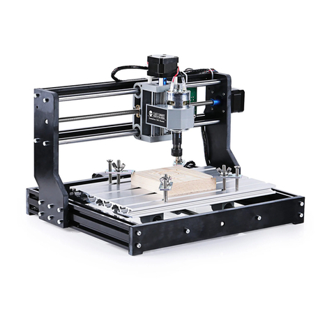
Genmitsu PROVerXL 6050 Plus User manual

PROVerXL 6050 Plus CNC Router
PROVerXL 6050 Plus CNC Dreh-/Fräsmachine
V1.0 Jun.2022
BENUTZERHANDBUCH
USER MANUAL
Genmitsu
Contents / Inhalt
English
Deutsch
01 - 40
41 - 80

Welcome
Disclaimer
Specifications
Part 1- Unboxing
Part 2- Mechanical Installation
Part 3- Wiring
Software Setup
Test Project
Z Probe Setup
01
02
03
04
09
29
33
36
38
Contents

01
Welcome
Thank you for purchasing the Genmitsu PROVerXL 6050 Plus CNC Machine from SainSmart.
Included in your package will be a USB Stick, you will find:
● PDF version of this manual
● Windows USB Driver
● GrbIControl/Candle software for Windows
● Sample files
Please visit SainSmart Online Resource Center installing drivers and software for your CNC.
https://docs.sainsmart.com/proverxl-6050-plus
The driver and software can also be found on the included USB stick.
For technical support, please email us at [email protected].
Help and support is also available from our Facebook group. (SainSmart Genmitsu CNC Users Group)
Scan QR code
to join the group

02
Disclaimer
Please be careful when using your CNC machine.This machine is an electrical device with moving parts and
dangerous areas.
● Genmitsu CNC Machines are for Indoor Use Only.
● You must be 18 years or older to operate this machine, unless supervised by a knowledgeable adult familiar
with the machine.
● Wear the proper Personal Protection Equipment (Safety Glasses etc.).
● Always place the CNC Machine on a stable surface.
● The SainSmart Genmitsu CNC Machine is supplied with Switchable Power Supply 230VAC or 115VAC. Never
use a different power supply; it may cause malfunctions or damage to the machine.
● The PROVerXL 6050 Plus utilizes a high amp power supply. It is recommended that you do not plug the CNC
Router into an extension cord, or power strip as it may damage the machine.
● Ensure the Emergency stop button is easily accessible at all times.
● Never disassemble the Power Supply or Electrical Components. This will VOID the warranty.
● DO NOT TOUCH the machine spindle, or place any body part near the working area when the machine is
operating.Serious injury may oCcur.
● DO NOT leave children unsupervised with the CNC Machine even when it's not operating. Injury may occur.
● DO NOT leave the machine unattended while it's operating.
● Ensure your CNC Machine is in a well-ventilated area. Some Materials may discharge smoke or fumes during
operation.

03
Specifications
Model Name
Work Area
Body Material
Drive System
Control Board Compatibility
Stepper Driver
Stepper Motors
Spindle
Extra Mount
Max speed
Running Accuracy
Repositioning Accuracy
Power Supply
CAM Software
Homing Switches
Leadscrew Size & Type
Linear Rails Size & Type
Overall machine size
Controller box size
PROVerXL 6050 Plus
600 x 500 x 115mm (23.62" x 19.69" x 4.53")
Metal Frame & T-Slot Hybrid Spoilboard
Dual linear rail with single Y-axis system
GRBL 1.1h
TB6560
NEMA 23, 3.1N-100mm
300W 6A, 12000RPM
65mm (the standard one is 52mm)
2000mm/min
±0.05MM
±0.05MM
600W,7A,0-48V
Candle, Carveco Maker, Easel
X, Y, Z Limit Switches + ESTOP
T10 2mm pitch, 5mm lead 5 start acme lead screw
EG-15 Linear Rails & HG-20 Linear Rails
991 x 782 x 641mm (39.02" x 30.79" x 25.24")
267 x 190 x 312mm (10.51" x 7.48" x 12.28")

04
Part 1- Unboxing
1XY Axis Base Assembly 2Lead Screw 3Bearing Fixing Plate 4(3) Motor Rubber
Gasket
5(3) Stepper Motor
with Motor Seat 6Left Gantry Support 7Right Gantry Support 8X-axis Assembly
952mm Spindle Holder 11 X-axis Limit
Switch Plate-1
X-axis Limit
Switch Plate-2
12
Mechanical Parts List
10 65mm Spindle Holder

05
Part 1- Unboxing
21 Spindle Motor
13 Y-axis Limit
Switch Plate-1 14 Y-axis Limit
Switch Plate-2 15 Y-axis Drag Chain
Mount-1 16 Y-axis Drag Chain
Mount-2
17 Y-axis Drag Chain
(Need to assemble) 18 X-axis Drag Chain 19 (2) Dust Baffle 20 (7) Aluminum &
MDF Hybird Slat

06
Part 1- Unboxing
Electrical Parts List
Tools/Accessories Parts List
(4) Rubber Feet
28 29 CNC Bits
23 Control Box
30 Bakelite Sheet
175 x 100 x 5mm
MDF Board
175 x 100 x 5mm
31
26 Allen Wrench
3.0mm, 4.0mm, 5.0mm
22 (2) Y-axis Limit Switch
27 Phillips Screwdriver
Z-Height
Mapping Probe
32 33 34 Material ClampWrench
USB Cable A-B
24 25 Power Cable

Screws/ Other Parts List
07
Part 1- Unboxing
42 (4) M4*4 Hex Screw
39 (8) M4*6 Countersunk
Phillips Head Screws
(4) M5*18 Hex Screw 46
44 (14) M5*25 Hex Screw
45 (20) M5*20 Hex Screw
41 (12) M5*12 Socket
Cap Screw
40 (4) M5*8 Socket
Cap Screw
36 (4) M3*20
Phillips Screw
(26) M5*16 Hex Screw
43
38 (12) M5 Spring Washer
35 (2) Bearing 37 (12) M5 Flat Washer

08
Part 1- Unboxing
Optional Accessories (Not Included)
Consider following optional upgrades or accessories to make your CNC experience better!
You can find them on www.sainsmart.com.
Save 10% with discount code PROVerXL
Scan QR codes to learn more
Aluminum Bench
Vise Clamp
CNC Router Bits
Essential Bundle Kit
Compressed Spot
Fixed Focus
FAC Laser Module
Φ52mm CNC
Dust Shoe

Installing the Y-axis Lead Screw
09
Part 2- Mechanical Installation
1. Install the bearing into the
circular opening at the center
of the frame.
2. Look for the anti-backlash
assembly on the Y-Axis, press
the screw nut of the Y-axis to
compress the spring while you
screw the leadscrew through
the assembly.
What you will need:
1XY Axis Base Assembly 35 Bearing
2Lead Screw
Bearing
Lead Screw
Screw Nut Longer Ends Stepped
XY Axis
Base Assembly

10
Part 2- Mechanical Installation
Installing the Y-axis Stepper Motor
What you will need:
35 Bearing
3Bearing Fixing Plate 4Motor Rubber Gasket 5Y-axis Stepper Motor
with Motor Seat
(8) M5*16
Hex Screw
4338 (4) M5 Spring Washer
37 (4) M5 Flat Washer
26 Allen Wrench

Bearing
Bearing Fixing Plate
M5*16 Hex Screws
Motor Rubber
Gasket Y-axis Stepper Motor with Motor Seat
M5 Flat Washer, M5 Spring
Washer and M5*16 Hex Screw
11
Part 2- Mechanical Installation
1. Install the bearing onto the other side of the lead screw and use the M5*16 hex screws to install the bearing
fixing plate.
2. Align the Y-axis stepper motor nut seat with the stepper motor gasket, install the M5*16 hex screws with a flat
washer first, then a spring washer to mount the stepper motor. (The motor seat opening of the mounting bracket
should face to the left of the CNC machine to make accessing in the future easier.)
3. Position the leadscrew coupler onto the motor shaft, be sure not to let the coupler rub against the frame of
the machine. The set screw should be positioned on the flat part of the stepper motor post. Tighten the set screws
until the motor can drive the screw when it is manually turned.

12
Part 2- Mechanical Installation
6Left Gantry Support 7Right Gantry Support
Installing the Left and Right Gantry Support
The rear of the machine is
towards the stepper motor. Align
each Gantry support (Left) and
right to the corresponding holes.
Each support will be angled
towards the read of the machine
as shown in the photo below.
Use the M5*20 hex screws for
loose fit-up. Do not tighten
completely.
What you will need:
45 (8) M5*20 Hex Screw
Left Gantry
Support
Y-axis Beam
Right Gantry
Support
M5*20 Hex Screw
26 Allen Wrench

13
Part 2- Mechanical Installation
(8) M5*16 Hex Screw
43
8X-axis Assembly
Installing the X-axis Assembly
What you will need:
1. Using the M5*16 hex screws,
install 1 on either side to help
support the X-Axis gantry while
you continue to finish placing
the assembly for a loose fit up.
2. After confirming that the
X-axis assembly is mounted
level, lock the M5*20 screws in
tightly on both sides of the
gantry supports
X-axis
Assembly M5*16
Hex Screws
26 Allen Wrench

14
Part 2- Mechanical Installation
Installing the X-axis Stepper Motor
What you will need:
4Motor Rubber Gasket 5X-axis Stepper Motor
with Motor Seat
(4) M5*16 Hex Screw
43
38 (4) M5 Spring Washer
37 (4) M5 Flat Washer
26 Allen Wrench

M5 Flat Washer, M5 Spring
Washer and M5*16 Hex Screw
Motor Rubber
Gasket
X-axis
Stepper
Motor
15
Part 2- Mechanical Installation
1. Align the X-axis stepper motor nut seat with the stepper motor gasket, install the M5*16 Hex screws with a
flat washer first, then a spring washer to mount the stepper motor (The motor seat opening of the mounting
bracket should face to the left of the CNC machine to make accessing in the future easier.
2. Position the leadscrew coupler onto the motor shaft, be sure not to let the coupler rub against the frame of
the machine. The set screw should be positioned on the flat part of the stepper motor post. Tighten the set
screws until the motor can drive the screw when it is manually turned.

16
Part 2- Mechanical Installation
Installing the Z-axis Stepper Motor
What you will need:
4Motor Rubber Gasket 5Z-axis Stepper Motor
with Motor Seat
38 (4) M5 Spring Washer
37 (4) M5 Flat Washer
(4) M5*16 Socket Cap Screw
41
26 Allen Wrench

17
Part 2- Mechanical Installation
1. Align the X-axis stepper motor nut seat with the stepper motor gasket, install the M5*16 Hex screws with a
flat washer first, then a spring washer to mount the stepper motor (The opening of the mounting bracket should
face to the back of the CNC machine to make accessing in the future easier.)
2. Position the leadscrew coupler onto the motor shaft, be sure not to let the coupler rub against the frame of
the machine. The set screw should be positioned on the flat part of the stepper motor post. Tighten the set
screws until the motor can drive the screw when it is manually turned.
M5 Flat Washer, M5 Spring
Washer and M5*16 Hex Screw
Motor Rubber
Gasket
Z-axis Stepper Motor

M5*12
Hex Screw
(4) M5*12 Socket
Cap Screw
41 45 (2) M5*20
Hex Screw
52mm
Spindle Holder
952mm Spindle
Holder 21 Spindle Motor
18
Part 2- Mechanical Installation
Use the M5*12 hex screws to install the 52mm spindle holder onto the Z-Axis Gantry Plate as shown in the
photos below.Insert the spindle motor into the holder and lock it in using the M5*20 hex screws.
Installing the Spindle Holder and the Spindle Motor
What you will need:
Spindle
Motor
M5*20
Hex Screw
26 Allen Wrench
Table of contents
Languages:
Other Genmitsu Control System manuals
Popular Control System manuals by other brands

Politec
Politec ALES QUAD Series Installation and mounting guide

Crestron
Crestron DIN Rail 4 Series quick start guide

Lectrotab
Lectrotab JLC Series Installation & operation

Franke
Franke DVS SH07-020 Installation & operating instructions

Compool
Compool Lx220 Installation & operating instructions

Infinity
Infinity Sidekick V1 user manual

micro-trak
micro-trak ProPlant Reference manual

Carrier
Carrier PRO-DIALOG PLUS 50AZ Installation, operation and maintenance instructions

Siemens
Siemens SIMATIC PCS 7 Getting started

BFT
BFT GIOTTO BT A ULTRA 36 Installation and user manual

YASKAWA
YASKAWA yasnac lx3 instruction manual

Varifan
Varifan IC-664 installation guide