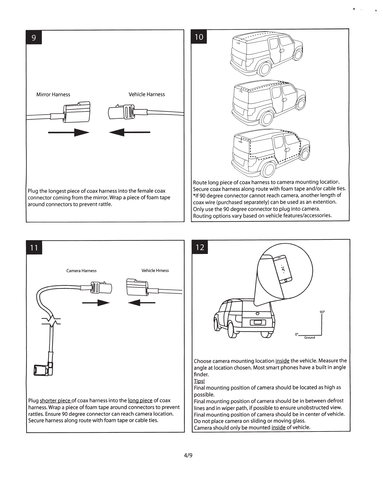
Mirror Harness Vehicle Harness
..
Plug
the
longestpiece
of
coax harness
into
thefemalecoax
connector
coming
from
the mirror.Wrap a piece
of
foam tape
around connectors
to
prevent rattle.
Camera
Harness
Vehicle
Hrness
t :
...
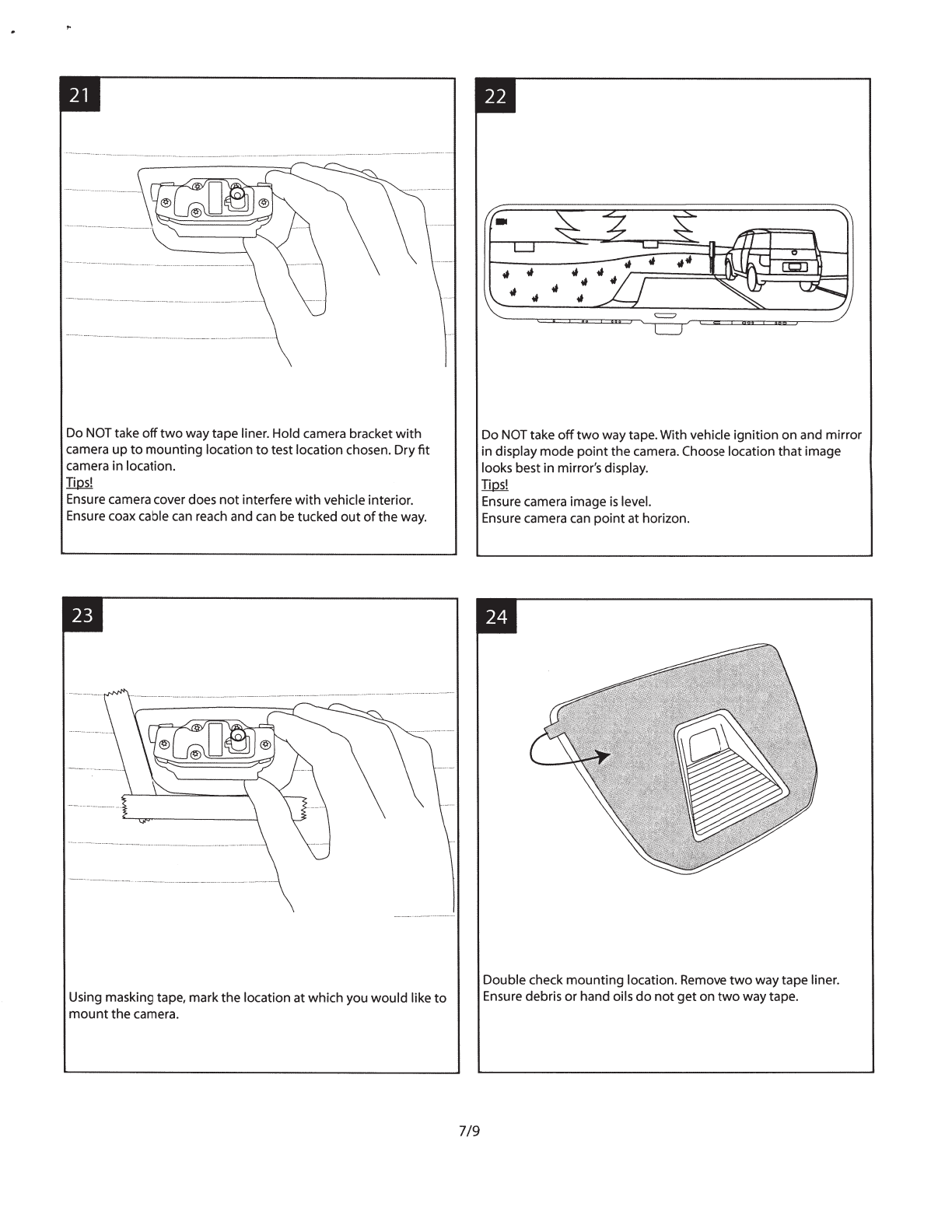
Plug shorterpiece
of
coax harness
into
the
long piece
of
coax
harness.Wrap a piece
offoam
tapearound connectors
to
prevent
rattles. Ensure 90 degree connectorcan reach camera location.
Secure harness along route
with
foam
tape
or
cable ties.
4/9
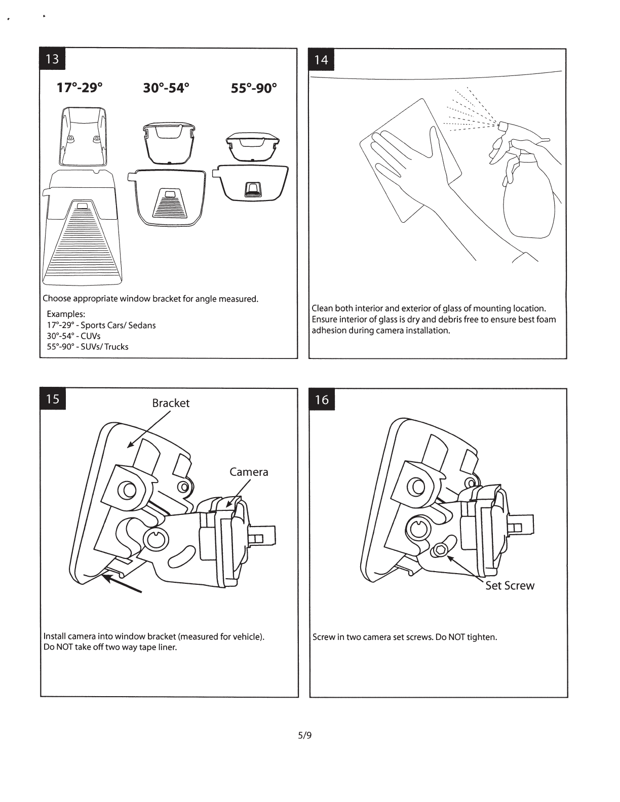
Route
long
piece
of
coax harness
to
camera
mounting
location.
Secure coax harness along
route
with
foam
tape
and/or
cable ties.
*If
90 degreeconnector
cannot
reach camera, another
length
of
coax wire (purchased separately) can be used
as
an
extention
.
Only
use
the
90 degreeconnector
to
plug
into
camera.
Routing
options
varybased
on
vehiclefeatures/accessories.
,._j
"
Gtound
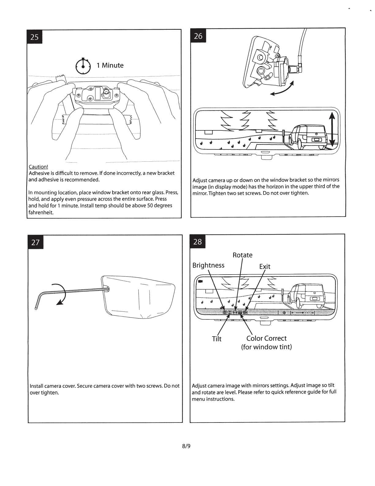
Choose camera
mounting
location inside
the
vehicle.Measure
the
angle
at
locationchosen.
Most
smart phones have a
built
in angle
finder
.
Iirul
Final
mounting
position
of
camera should
be
located
as
high
as
possible.
Final
mounting
position
of
camera should
be
in
between
defrost
lines and
in
wiper
path,
if
possible
to
ensure
unobstructed
view.
Final
mounting
position
of
camera should
be
in
center
of
vehicle.
Do
not
placecamera
on
sliding
or
moving
glass.
Camera should
only
be
mounted
inside
of
vehicle.
..