GeoBox G-105 User manual

G-105 User Manual Document: G-105-01
------------------------------------------------------------------------------------------------------------------------------------------------
1
G-105 User Guide
OFF
ON
VGA IN
DC IN
12V 2.0A
DisplayPort DVI-I RS-232
HDMI
OUTPUT INPUT CONTROL
IR Ext
Model No: G-105
Made in Taiwan
DVI-D
MENU ENTER
AUDIO
OUT
AUDIO
IN IR MANUAL INFO
INPUT OUTPUT
Exit Multi-function
video processor
G-105
®
GeoBox
OSDAudio
PROFILE INDEX
SPDIF OUT
PWR OUT
Audio
HDMI VGA IN
IN
#1 #2 #3 #4 #5
Multi-function video processor

G-105 User Manual Document: G-105-01
------------------------------------------------------------------------------------------------------------------------------------------------
2
Table of Contents
1 Introduction……………………………………………………………..……………….… 5
2 Features.........…………………………………………………………..………….……… 5
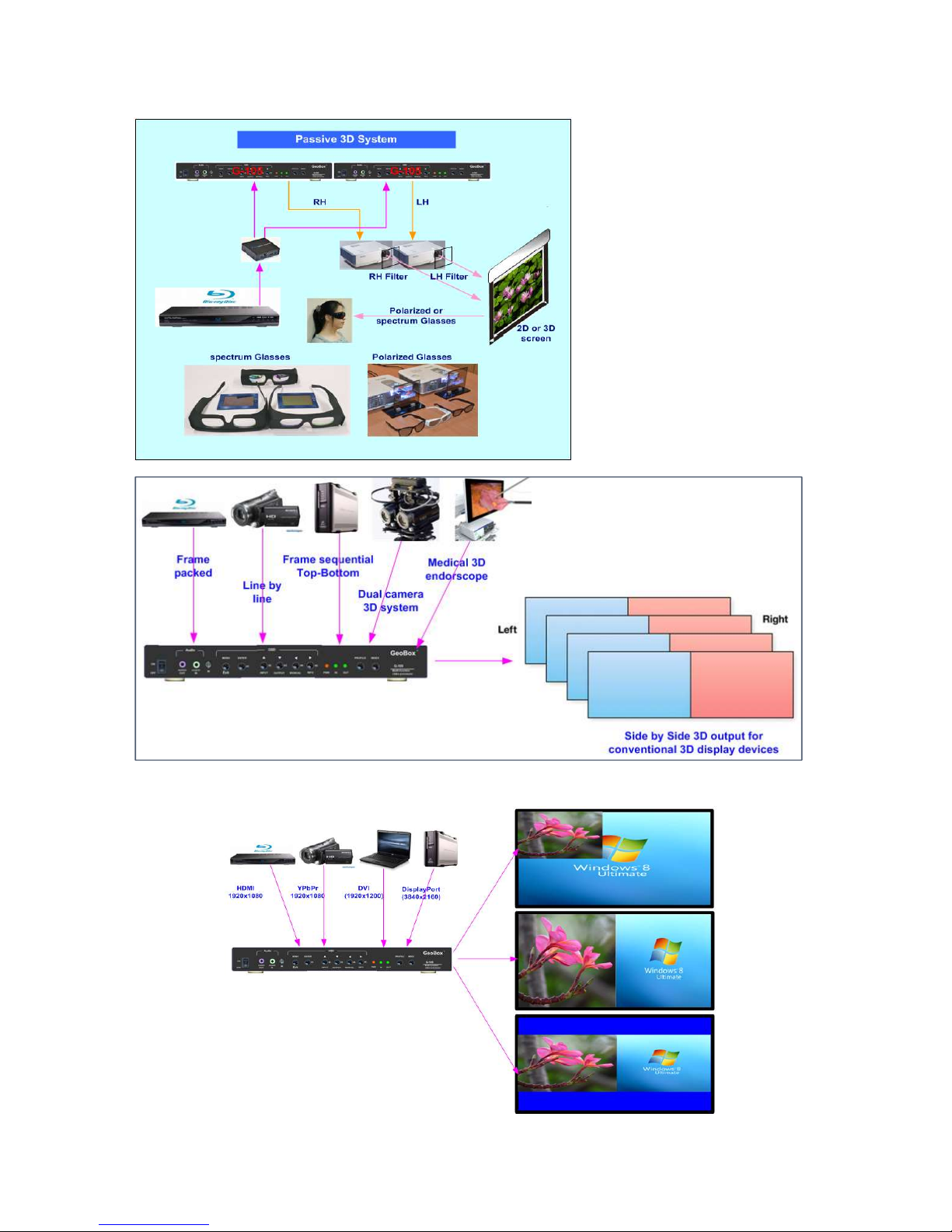
3 Application case studies.......................................................................................... 8
4 Helpful tips for installation and operation…………………………………….……... 14
5 Outlook and key functions………………………………………..………………….…. 15
6 Remote controller operation.................................................................................... 15
7 OSD menu and functions……………………………………………….....……………. 16
7.1 [Picture] color adjustment………………………………………………………… 16
7.2 [Image Setup] for VGA input……………………………………....................…. 16
7.3 [Image Properties]………………………………………………………….……… 17
7.3.1 Color.………………………………………………………………………........ 17
7.3.2 Input signal................................................................................................ 17
7.3.3 Scaling………………………………………………………………………….. 18
7.3.4 Output Mode.............................................................................................. 18
7.3.5 PIP/POP settings…………………………………………………………….... 18
7.3.6 Image Orientation (Flip & Rotation).………………………………………. 21
7.4 Video wall setting……………………………………………............................... 21
7.4.1 Zoom: Split image into different sections……………………………... 21
7.4.2 Pan: Select cropping area..................................................................... 22
8 Passive 3D Display.................................................................................................... 23
8.1 System configuration...................................................................................... 23
8.2 GeoBox setup for Stereoscopic 3D Display................................................... 23
8.3 Procedures for passive 3D setting in GeoBox............................................... 24
8.4 3D signal conversion........................................................................................ 25
9 [Anyplace]: Warp and geometry correction............................................................ 25
9.1 [Keystone] correction....................................................................................... 26
9.2 [Image Rotation]................................................................................................ 27
9.3 [4 Corner] adjustment....................................................................................... 27
9.4 [Warp]: Image curved display........................................................................... 28
9.4.1 [Corner] curve adjustment......................................................................... 28
9.4.2 [Edge] curve adjustment............................................................................ 29
9.4.3 [Center] curve adjustment......................................................................... 30
9.4.4 [Shift]: Corner position adjustment........................................................... 30
9.4.5 [Order].......................................................................................................... 31
9.5 [Manual Mode]: Crop any location of the image............................................. 31
9.5.1 Select custom mode storage location...................................................... 32
9.5.2 Crop image for each Index......................................................................... 32
9.5.3 [Ratio]: Adjust custom mode aspect ratio and position......................... 33
9.5.3.1 Horizontal [Ratio] adjustment..................................................... 33
9.5.3.2 Vertical [Ratio] adjustment……………...………………………… 34

G-105 User Manual Document: G-105-01
------------------------------------------------------------------------------------------------------------------------------------------------
3
9.5.3.3 Horizontal [position] adjustment…………………………........… 35
9.5.3.4 Vertical [Position] adjustment……………………………..…....... 35
9.5.3.5 [Reset]: Reset [Ratio] and [Position] to default......................... 36
9.5.4 [Loop]—Looping playback and project LCD from burn-in mark............ 36
10 Procedures to create custom display................................………………………….. 38
10.1 Introduction………………………………………………………............................ 38
10.2 Collect coordinates from physical drawing………………...........................… 38
10.3 Collect coordinates from photo....................................................................... 40
10.4 Upload coordinates via OSD menu.................................................................. 40
10.5 Upload coordinates and position fine-tune via remote controller................ 41
11 [Options]: OSD Miscellaneous Functions………………………………………......... 41
11.1 [Information]: System Information………………………………………............ 41
11.2 [Language]: OSD language………………………………………………............. 42
11.3 [Reset]………………...........………………………………………………………… 42
11.4 [Accessibility]………………………...........……………………………………….. 42
11.4.1 [Bottom Repeat Rate]......................................................................... 42
11.4.2 [Menu Time Out]………………………………………………………… ... 43
11.4.3 [Logo Time out]………………………………………………………….... 43
11.4.4 [Standby Time Out]……………………………………………………..... 44
11.5 [Setting]………………………………………………………………………............ 44
11.5.1 Frame Lock and Free Run mode……………………………………..... 44
11.5.2 [Box ID]…………………………………………………………………...... 45
11.5.3 [Profile] setting………………………………………………………….... 45
11.5.4 [Network]…………………………………………………………………... 46
11.5.5 [EDID] setting..........................................................................……….. 46
12 GAlign PC tool (Image cropping tool)...................................................................... 48
12.1 Download and decompress.............................................................................. 48
12.2 Operation procedures....................................................................................... 48
13 GPM system setting backup tool............................................................................. 50
13.1 Purpose.............................................................................................................. 50
13.2 GPM installation................................................................................................ 50
13.3 System connection........................................................................................... 50
13.4 Instructions........................................................................................................ 50

G-105 User Manual Document: G-105-01
------------------------------------------------------------------------------------------------------------------------------------------------
4
Revision History
Revision
Date Originator Comments
V 1.01 2016-09-20 Steve Wang First revision
V1.02 2016-11-22 Steve Wang Remove internal test pattern, add PC tool and [Shift]
shortcut key
V1.03 2016-07-07 Steve Wang Increase Index modes # and warp adjustment range.
Limited Warranty
This device is designed and tested to the highest standards and backed by two years’ parts and labor warranty.
Warranties are effective upon the first delivery date to the end customer and are non-transferable. Warranty
related repairs include parts and labor, but do not include repair of faults resulting from user negligence, special
modifications, abuse (mechanical damage), shipping damage, and/or other unusual damages. The customer shall
pay shipping charges when the unit is returned for repair. Manufacturer will pay shipping charges for return
shipments to customers.
Manufacturer does not assume responsibility for consequential damages, expenses or loss of revenue,
inconvenience or interruption in operation experienced by the customer. Warranty service shall not automatically
extend the warranty period.
FCC/CE statement
This equipment has been tested and found to comply with the limits for a Class A digital device, pursuant to part 15
of the FCC Rules. These limits are designed to provide reasonable protection against harmful interference when
the equipment is operated in a residential / commercial environment. This equipment generates, uses, and can
radiate radio frequency energy and, if not installed and used in accordance with the instruction manual, may cause
harmful interference to radio communications. Operation of this equipment in a residential area is likely to cause
harmful interference in which case the user will be required to correct the interference at his own expense.

G-105 User Manual Document: G-105-01
------------------------------------------------------------------------------------------------------------------------------------------------
5
1 Introduction
Image magician G-105 is multiple purpose video processor with warp, de-warp, video wall control, format
conversion, scaler switcher, PIP/POP, 3D format conversion, image cropping, flip/rotation, dynamical aspect ratio
adjustment, continuous position shift and seamless looping playback for different display modes. Two landscape
contents can be displayed on one portrait LCD at top/bottom position. It can also provide medical image de-warp,
3D conversion for endoscope (from dual camera format or Line by Line to Side by Side).
G-105 is pure hardware standalone system. It can connect with various video sources and provide a simple
and reliable solution for professional creative video.
2 Features:
2.1 Input and output:
Video Input: 1xHDMI, 1x VGA, 1x DisplayPort, 1x DVI-I (support HDMI, DVI, VGA)
Max. input resolution:
4K/2K @30HZ, 3840x1080 @60Hz in HDMI & DP ports, WUXGA in VGA & DVI-I ports.
Video Output:
--1x HDMI, 1x DVI-D (mirrored)
--Selectable output resolutions, Max. output resolution: 1920*1200.
Audio input: HDMI embedded audio, PC audio jack.
Audio output: 1x SPDIF RCA output, HDMI embedded audio.
DisplayPort and HDMI/DVI support WQXGA & 3840x1080 @60Hz、4k/2k @30Hz input with 4:4:4 full
color sampling without compression.
2.2 Warp and geometry alignment:
Quick corner adjustment, H&V keystone correction.
Pincushion and barrel adjustment.
Geometry alignment through remote controller up to 3x3 grids.
16:9 and 2.35:1 aspect ratio conversion.
2.3 Image stacking
Image stacking to increase brightness on flat and curved screen.
2.4 Image flip and rotation
Image rotation at 90/180/270 degrees with full screen display.
Image rotation with 1 degree interval without changing image aspect ratio.
Image flip at Front/Rear, Right/Left, Top/Bottom directions.
Mobile image 90/270〫rotated and scaled up to full screen at portrait LCD.
2.5 3D application:
Connecting with all kinds of 3D signal sources: Blue Ray, Set Top Box, PC…
Support 1080p @120Hz Nvidia 3D Vision for full HD passive 3D display.
Support HDMI 1.4a 3D formats, including 1080p/24Hz frame packed, Side by Side, Top-Bottom, Line by

G-105 User Manual Document: G-105-01
------------------------------------------------------------------------------------------------------------------------------------------------
6
Line and frame sequential for passive 3D display.
Support 3840x1080 side by side and 1080i/60Hz frame packed 3D from Sony FHD 3D camcorder.
Support PIP function in passive 3D display, both main and PIP windows are still with 3D effect.
Perfect Synchronization algorithm in RH/LH channels to get the most comfortable passive 3D display.
Support passive 3D image geometry alignment, curved screen display and stacking.
Convert discrete dual RH/LH 3D signals into one side by side 3D format.
Convert line by line 3D format into side by side 3D format.
2.6 High end video processing
10-bit high bandwidth processor with 3D motion adaptive de-interlace, low angle smooth algorithm and
3:2/2:2 film mode detecting and recovery.
Support up to 4k/2k @30Hz input with 4:4:4 full color sampling without compression.
Intelligent color adjustment, including preset color, hue, saturation, brightness, contrast sharpness
adjustments and RGB discrete color adjustment.
2.7 Format conversion
Convert below input signal formats into HDMI or DVI-D (mirrored) outputs:
DisplayPort, HDMI, DVI-D, DVI-A, VGA and YPbPr (through DVI-I or VGA port)
2.8 Video wall function
Video wall function to split, crop and location assignment with pixel based cropping range adjustment up
to 900 pixels at H&V directions.
Pixel by pixel precise bezel compensation.
Video wall control up to 15x15 matrix displays.
Image PIP/POP, flip and rotation function can be applied to video wall.
Input Top Left and Top Right corner coordinates to crop image of irregular video wall.
2.9 Image any location cropping and position shift
There are four ways of image cropping through OSD & remote controller:
[Video Wall] menu: ZOOM, PAN and OVERLAP
In combination with image split (ZOOM), location assignment (PAN) and H&V 900 pixels cropping
position shift function (OVERLAP), user can crop any location of the image to show on the screen.
[WARP] menu
User can use Warp function to do geometry adjustment, including image resizing, accurate position and
change the shape of the image.
[Manual Mode] menu under [Anyplace]
Menu mode can catch any 16:9 image at any rotation angle through input Top Left and Top Right corners’
coordinates.
PC Tool: user can capture arbitrary area image with 16:9 aspect ratio through GAlign PC tool.
2.10 Aspect ratio adjustment
User can adjust image aspect ratio through below functions:
User can adjust output image aspect ratio in the range of 067%-200% in H&V directions through [Ratio]

G-105 User Manual Document: G-105-01
------------------------------------------------------------------------------------------------------------------------------------------------
7
hotkey on remote controller or [Ratio] menu under [Manual Mode] from any signal source. If the image is
cropped through [Manual Mode], the adjusting range is from 25%-200%.
[Overlap] function under [Video Wall] menu can execute Aspect Ratio adjustment by changing image
cropping range.
[Warp] function can also adjust the image aspect ratio.
2.11 Dynamic image position shift
The image captured through [Manual Mode] can do dynamic position shift after the aspect ratio has been
changes. The adjustment range is based on the same ratio as aspect ratio change. The maximum range
is 0.25~2.0 in both H&V directions.
This kind of dynamic position shift can be stored into Index 1-10 and user can execute seamless looping
playback for these display modes.
2.12 PIP/POP Multiple windows display
PIP function with selectable input port in both main and PIP display windows
Flexible image size, aspect ratio and position adjustment through OSD or IR controller
Max. PIP size is 1024x768 resolution
POP function with selectable full screen or original aspect ratio.
POP supports two landscape contents to displays in one portrait LCD at top/bottom position.
2.13 Looping playback with different display mode
User can select different display modes created from [Manual Mode] menu for looping playback with
selected time interval. Maximum display modes can be selected is 10.
The display modes created from Aspect Ratio adjustment and Image Position shift can be selected for
looping playback.
2.14 LCD burn-in mark protection
User can set multiple display modes with slight image position shift and execute looping playback. It
can eliminate burn-in mark in the LCD while display content is still image.
2.15 Image de-warp for camera or video system
Image de-warp can be implemented through Warp function.
De-Warp function can be used to correct image distortion. It can be also applied to de-warp for
medical endoscope and fish eye lens in surveillance system.
2.16 3D signal conversion
In addition to projector active 3D and passive 3D applications, G-105 can convert below 3D formats into one
Side by Side 3D format output:
RH/LH discrete 3D format
Line by line (line interleaved)
Frame packing
Frame sequential
Top-bottom 3D.
2.17 System control & others

G-105 User Manual Document: G-105-01
------------------------------------------------------------------------------------------------------------------------------------------------
8
Reliable and durable design for long term industrial and commercial applications.
Full functional keypads & IR control.
ID # for each GeoBox. Convenient for system installation and control.
keypad Lock (press menu key for 5 seconds) to avoid setting loss due to negligence..
Up to 5 settings can be saved and recalled at any time.
Integrated with IR extender (up to 20 meters) & RS-232 control port.
Dimension and weight: 303x155x44mm, 2.35k
3 Application case studies
3.1 Image warp and geometry alignment
3.2 Image stacking for flat and curved screen
3.3 Image flip and rotation

G-105 User Manual Document: G-105-01
------------------------------------------------------------------------------------------------------------------------------------------------
9
(Display mobile image on portrait LCD)
(Rotate image and adjust aspect ratio)
(360 degrees Image rotation with one degree interval and maintain original aspect ratio)
3.4 Image flip
Image flip and POP to get
portrait display with two
landscape contents

G-105 User Manual Document: G-105-01
------------------------------------------------------------------------------------------------------------------------------------------------
10
3.5 3D application
3.6 Image PIP with flexible size, position and aspect ratio
3.7 Image POP (side by side) for landscape and portrait display
Passive 3D display system
Decode all kinds of 3D signal with
side by side output for conventional
3d display devices and bare eye 3D
system
Decode all kinds of 3D signal with side by
side output for conventional 3d display
devices and bare eye 3D system

G-105 User Manual Document: G-105-01
------------------------------------------------------------------------------------------------------------------------------------------------
11
3.8 Dynamic aspect ratio adjustment
3.9 Any location cropping with 16:9 aspect ratio at arbitrary angle
POP with dynamic aspect
ratio and position shift. No
source image rotation is
required.

G-105 User Manual Document: G-105-01
------------------------------------------------------------------------------------------------------------------------------------------------
12
3.10 Dynamic image position shift
3.11 Looping playback with different display mode settings from single content

G-105 User Manual Document: G-105-01
------------------------------------------------------------------------------------------------------------------------------------------------
13
3.12 Irregular video wall with multiple units of G-105

G-105 User Manual Document: G-105-01
------------------------------------------------------------------------------------------------------------------------------------------------
14
4 Helpful tips for installation and operation
4.1 G-105 has no internal grid pattern. If user needs grid pattern, external grid pattern from PC or media player
shall be applied.
4.2 System reset: In some application, during operating, user may not see OSD menu and can’t execute system
reset. Below are the methods to do system reset:
a. Press any other INDEX key on remote controller or front panel, user will see full OSD to do system reset.
b. Use a small pin and press Tact switch inside the small hole next to Power switch on front panel for 5
second, it will reset the system.
4.3 Each G-105 is equipped with IR extenders. User can extend the cable distance up to 20m through audio cable.
4.4 RS232 is available for system control. User can use USB to RS232 conversion cable for the connection.
4.5 OSD Lock / Unlock: When continuously press [MENU] key in IR Remote Controller for 5 seconds, the OSD
function will be locked to prevent from changes of the settings. To press MENU key for 5 seconds again, it will
unlock OSD and user can manipulate OSD again.
4.6 Box ID allows user to control multiple G-105 at the same time without interference. Press remote controller
number keys as below and then function keys to execute OSD control:
851: control #1 G-105
852: control #2 G-105
850: control all G-105
4.7 Picture menu in the OSD can only be activated while the input signal is not in [Preset Mode] color setting. To
select [Image Properties] [Custom] [Save], then user can activate [Picture] menu again.
4.8 [Image Setup] menu will not be activated if the input source is not from VGA.
4.9 User can store the final settings in PC and copy the same settings to other units by GPM PC tool.
4.10 Poor signal cable connection or too long cable may cause noise on the display. Re-connect or replace a new
cable may solve the problem. High speed HDMI cable with Ethernet function is recommended.

G-105 User Manual Document: G-105-01
------------------------------------------------------------------------------------------------------------------------------------------------
15
5 Outlook and key functions
(Function keys are only available when the OSD menu is not activated)
6 Remote controller operation
RC-700 remote controller
Index locations for manual
display modes storage
(1-3+4-10)
Video wall Main menu
Image position adjustment
Pattern for geometry alignment
Image aspect ratio adjustment
Top Right coordinate menu
Top Left coordinate menu
Profile
selection
Manual mode
Index selection
Manual mode
Index number
OSD
Menu/Exit
Input port
selection
Output resolution
selection
Manual Mode
Menu shortcut
OSD
Enter
Input port selection
Output resolution selection
Cropped image location shift
OSD operation

G-105 User Manual Document: G-105-01
------------------------------------------------------------------------------------------------------------------------------------------------
16
7 OSD menu and functions
User can use keypads on front control panel or IR remote controller to activate OSD menu. IR Receiver
extender can be extended up to 20 meters with audio cable.
IR remote controller IR Receiver Extender
When OSD menu is activated, all other shortcut key functions on front control panel will be disabled. These
functions include: Input selection, Output resolution setting, Manual display mode menu and Index key
functions.
7.1 [Picture] Color Adjustment
a. This menu is only available under below conditions:
[Picture] menu will be grayed out and not functional when the color setting is in [Preset Mode] under
[Image Properties] menu. User needs to get into [Custom] menu and press [Save] menu to activate
[Picture] menu.
When the input signal is in YUV domain, all the items under menu are free to be accessed.
If the input signal is in RGB domain, only [Brightness] and [Contrast] can be adjusted.
b. User can do further separate RGB individual color adjustment under [Image Properties] menu.
7.2 [Image Setup] for VGA input
Five items under [Picture] menu.
Brightness
Contrast
Hue
Saturation
Sharpness

G-105 User Manual Document: G-105-01
------------------------------------------------------------------------------------------------------------------------------------------------
17
a. Automatic: It will do automatic image alignment inside the system
b. Manual: manual setting for signal Phase and Clock to eliminate image noise in analog input
c. Horizontal Position: to adjust manually the image horizontal position.
d. Vertical Position: to adjust manually the image vertical position.
e. When the input is VGA signal, please connect signal to G-105 first, then turn on G-105 for image
position auto alignment. After this process, unless user applies other VGA input signal, G-105 will
not do auto alignment again to avoid image shift.
7.3 [Image Properties]
[Image properties] is designed to select image color temperature, adjust independent RGB color, select input
port & output resolution, set display aspect ratio, set PIP/POP function and image flip/rotation. There are six
sub-menus.
7.3.1 Color
7.3.2 Input Signal
[Image Setup] menu can only be activated when
video input is from analog VGA input signal.
Under [Color] menu:
4 Preset modes for color temperature selection
[Custom]: Independent RGB color adjustment.
Under this menu, if user select [Save], then
[Picture] menu will be activated for access
Six sub-menus:
[Color]: Color temperature selection and RGB
independent adjustment
[Input Signal]: to select input port
[Scaling]: to set display aspect ratio
[Output Mode]: to select output resolution
[PIP setting]: to do PIP/POP settings
[Orientation]: image flip and rotation setting

G-105 User Manual Document: G-105-01
------------------------------------------------------------------------------------------------------------------------------------------------
18
7.3.3 Scaling
7.3.4 Output Mode
7.3.5 PIP/POP Setting (Picture in Picture & Side by Side)
User can set PIP/POP function through this
menu.
POP image aspect ratio shall be determined
from [Scaling] menu.
User can combine PIP/POP function with other
function like [Orientation] or [Video wall] setting
to perform different display styles.
[Full Screen]:
To fit source image for full screen display
[Original AR]
To display source image with the same aspect
ratio as source image
The setting will also affect POP image display
with full screen or original aspect ratio.
User can select input port from this menu or
shortcut keys on remote controller and front
control panel.
VGA and DVI-A input are through the same
input port in the system. User can’t use these
two input ports at the same time.
11 preset output resolutions can be selected from
this menu.

G-105 User Manual Document: G-105-01
------------------------------------------------------------------------------------------------------------------------------------------------
19
Picture in Picture (PIP) function is to display two images from one G-105. The maximum size of the
sub-image (PIP) is 1024x768 pixels. The input source for PIP is selectable and can be from any input port of
G-105. The input for main and PIP image can be the same or swapped. The location of the PIP image can be
controlled by OSD menu at any location inside main image. The size of the PIP image is also flexible and can
be controlled by OSD menu as well. Unless the image is rotated at 90/270 degrees, both main and PIP image
will go through high end 3D motion de-interlacing. When the image is 90/270 rotated, please apply
progressive signal source to get the best video quality.
Display: Under Display menu, there are three items:
Disable: to Disable PIP or POP function
PIP: to select PIP display function
POP: to select POP (side by side) display mode. User can select maintain original image aspect ratio or
full screen mode through [Scaling] OSD menu under [Image properties].
Size: (Only apply to PIP function)
The size of the PIP image can be adjusted though [Size] OSD menu pixel by pixel.
The maximum size of PIP image is 1024x768 pixels. If user sets output resolution at 1024x768
resolution, PIP image can be displayed with full screen in the output.
Position: (only apply to PIP function)
The position of PIP image can be adjusted in H&V directions through Position OSD menu.
The PIP image will be maintained inside main image and can’t be outside main image.
Pixel by Pixel PIP image position adjustment.
Five sub-menus under [PIP setting] menu,
--Display: enable PIP or POP
--Size: set PIP size
--Position: set PIP position
--Ratio: set PIP display aspect ratio
--Source: select input source for PIP/POP

G-105 User Manual Document: G-105-01
------------------------------------------------------------------------------------------------------------------------------------------------
20
Ratio: Aspect Ratio of the display image. (Only apply to PIP function)
Full Screen: the same aspect ratio as main image or
Original AR: the same aspect ratio as PIP input source.
POP image aspect ratio can be adjusted through [Scaling] under [Image Properties] OSD menu.
Source: User can select the input source for PIP/POP image from all input ports. By selecting different
input ports for Main & PIP/POP images, user can have different combination of the display. User can
save different settings into [Profile] under [Option] menu and recall at any time.
(Please note that VGA and DVI-A input is through the same input port in the system. User can’t use
these two input ports at the same time.)
Rotating function combined with PIP/POP
User can apply image flip and rotation function with PIP/POP (please see next section). When apply
POP function and rotate the image at 90/270 degrees, user can display two landscape contents on
portrait LCD at Top/Bottom location. User can select full screen or maintain original aspect ratio
through [Scaling] menu under [Image Properties].
User can use [Ratio]/[Position] shortcut keys on remote controller or [Ratio]/[Position] menu under
[Manual Mode] [Ratio] to change aspect ratio and shift image position.
Table of contents
Other GeoBox Media Converter manuals