GeoCue True View 600 Series Installation manual

True View 600 Series Hardware User Guide
10/26/2021
GeoCue Group, Inc
10/26/2021
Version 1.1.7
Updated for Firmware Version 3.0.7.1

True View 600 Series Hardware User Guide
2 True View 600 Series Hardware User Guide 10/26/2021
Contents
About GeoCue Group, Inc. ......................................................................................................................4
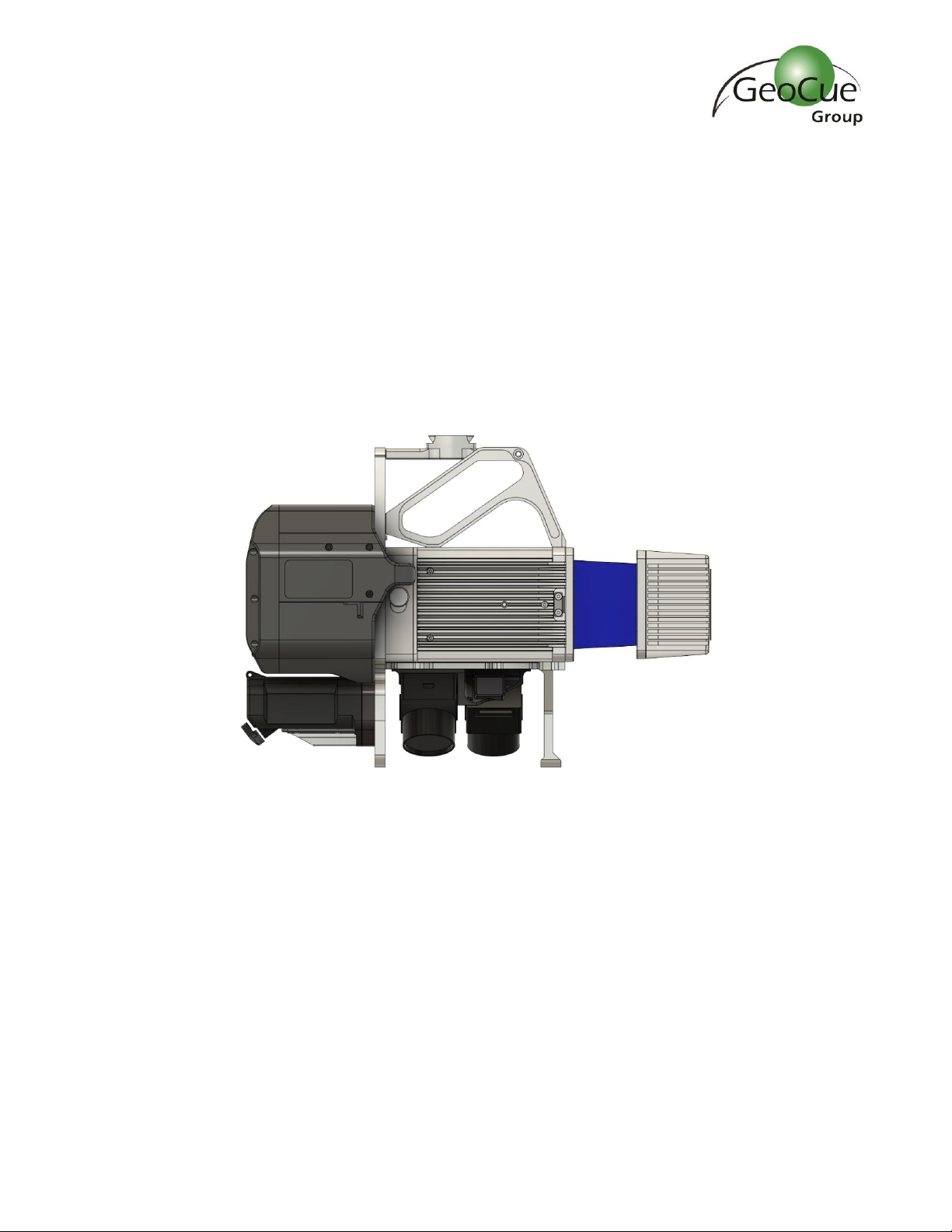
About True View® 600 Series.................................................................................................................. 5
A True View Cycle ................................................................................................................................... 5
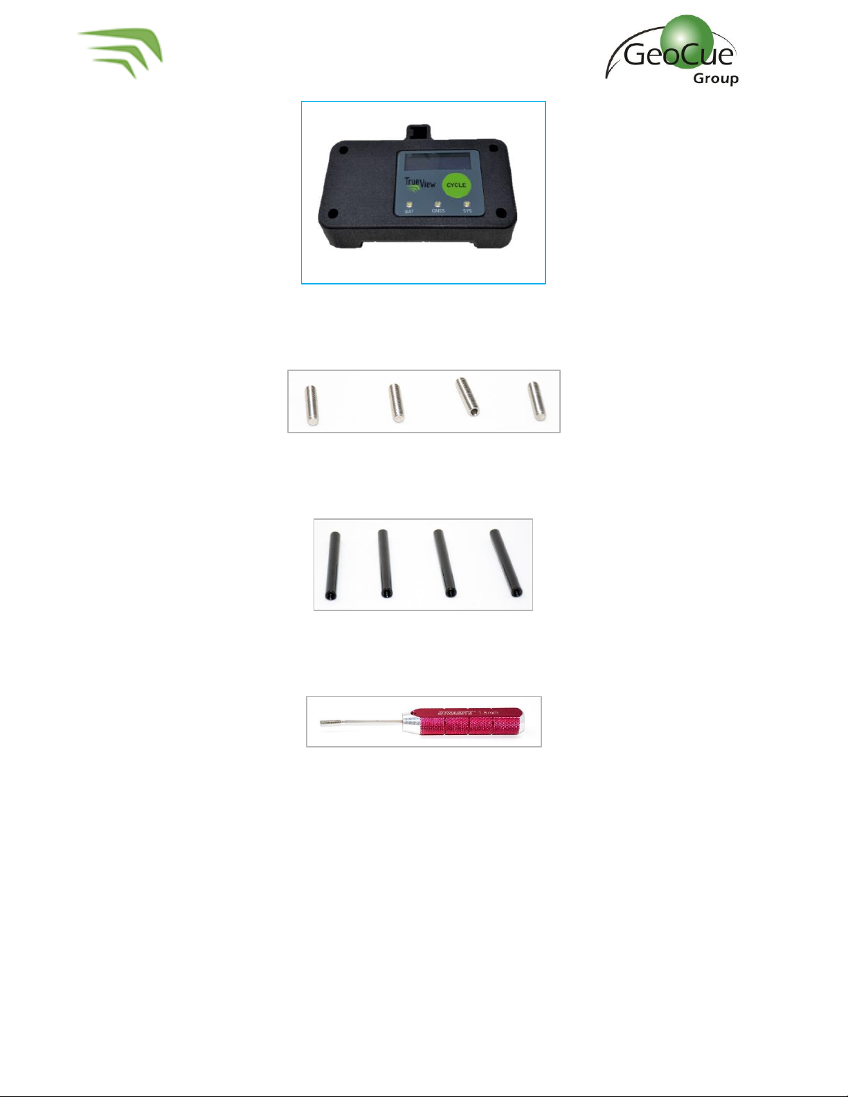
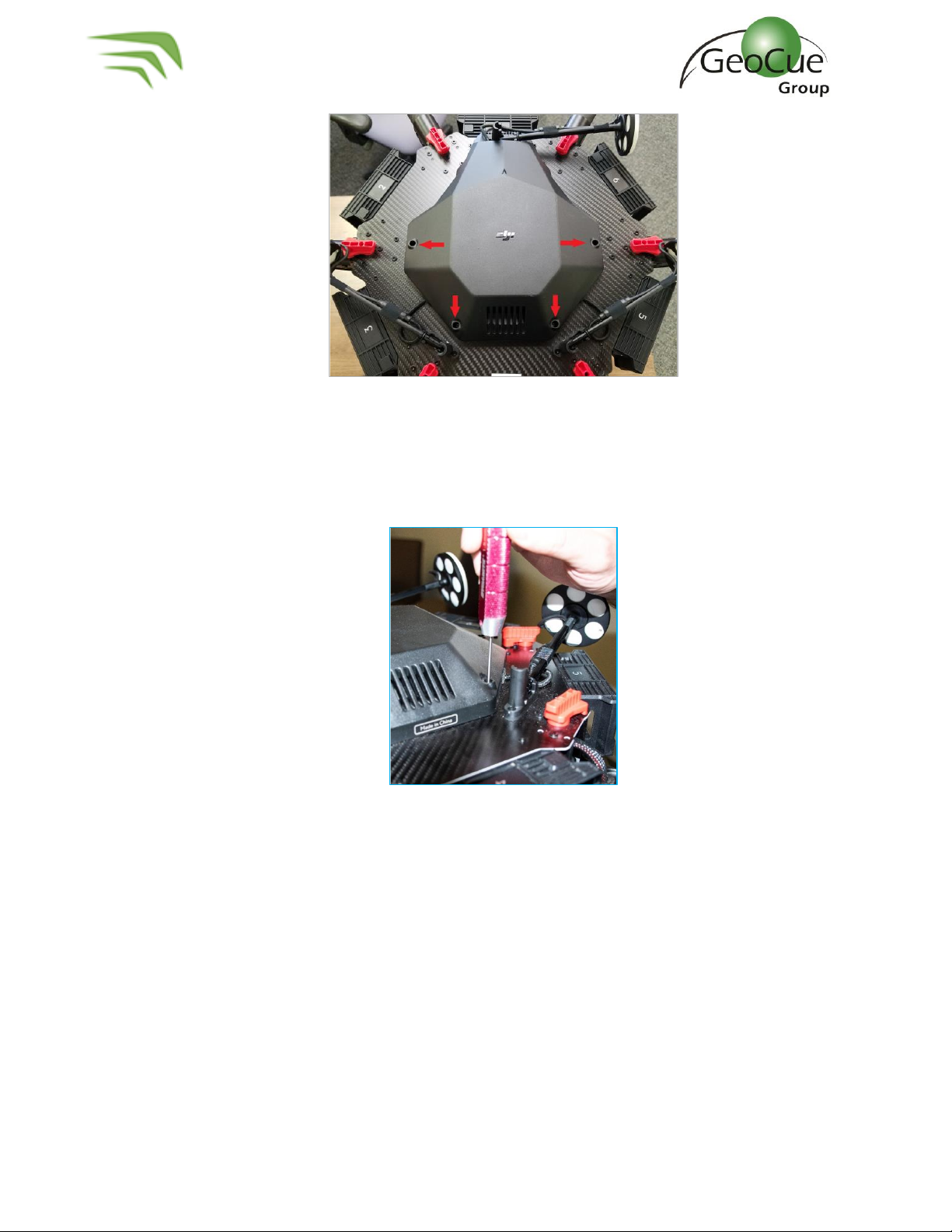
True View Hardware Integration Kit (M600)............................................................................................6
Installing the Top Plate and Controller Box .........................................................................................6
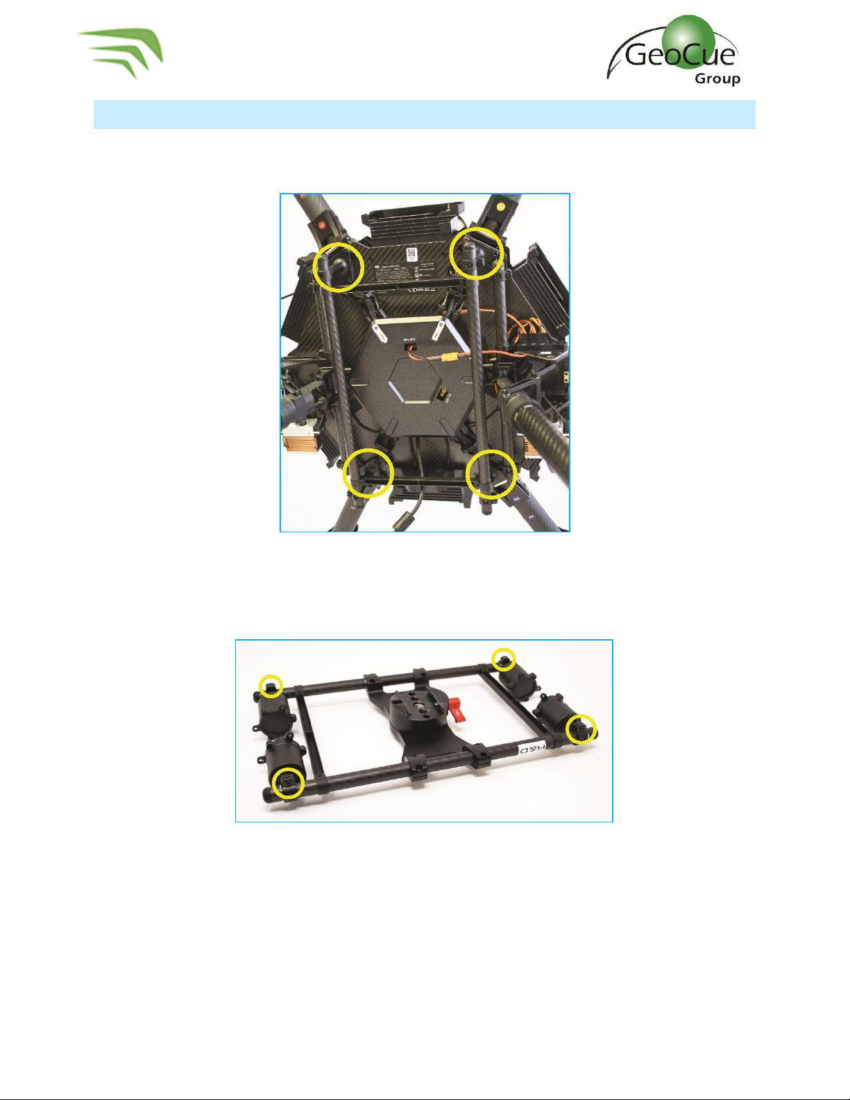
Installing the Ronin Mount ................................................................................................................ 10
True View 600 Series Installation .......................................................................................................... 12
True View Battery ................................................................................................................................. 16
True View Data Storage Devices............................................................................................................17
UMS...................................................................................................................................................17
Camera SD Cards ...............................................................................................................................17
System Configuration File (SCF)........................................................................................................ 18
Core Configuration File (CCF)............................................................................................................ 18
CCFSection6 –POS ....................................................................................................................... 18
CCFSection8 –Camera.................................................................................................................. 19
CCFSection11 –Configuration Laser..............................................................................................20
CCFSection15 –Battery................................................................................................................. 21
CCFSection16 - Cycle ....................................................................................................................22
CCFSection17 –Storage Auto Delete ............................................................................................ 23
True View 600 Series Field Operations..................................................................................................24
1. Base Station ..............................................................................................................................24
2. Pre-Flight .................................................................................................................................. 25
3. Controller Box LEDs .................................................................................................................. 27
4. Heading Alignment Maneuver...................................................................................................29
5. After Landing ............................................................................................................................ 30
True View EVO...................................................................................................................................... 31
Logging in To APX15............................................................................................................................. 32
Configure True View Wi-fi ................................................................................................................. 32
Log in to APX-15 ............................................................................................................................... 33
Download T04 Files....................................................................................................................... 33

True View 600 Series Hardware User Guide
3 True View 600 Series Hardware User Guide 10/26/2021
Measuring GNSS Lever Arm Offsets ..................................................................................................... 35
Z Offset............................................................................................................................................. 36
X Offset............................................................................................................................................. 37
Y Offset............................................................................................................................................. 38
True View 3DIS/M600 Pro –Mission Checklist....................................................................................... 39
FAQ ...................................................................................................................................................... 41
Support.................................................................................................................................................42

True View 600 Series Hardware User Guide
4 True View 600 Series Hardware User Guide 10/26/2021
About GeoCue Group, Inc.
GeoCue Group was founded in 2003 by a group of engineers with extensive experience in developing
hardware and software solutions for primary remote-sensed data acquisition. Our initial products were
aimed at reducing schedule and cost risk in geospatial production workflows by providing
organizational, productivity and data management tools for base geospatial data production. These
tools have been realized as the GeoCue product family. Today GeoCue workflow management tools are
used by a majority of North American geospatial production shops. In 2005, GeoCue began selling and
supporting Terrasolid tools for kinematic LIDAR data production. This was followed in 2009 by our
acquisition of QCoherent Software LLC, the creator of the point cloud exploitation toolset, LP360.
Today GeoCue is the largest supplier of kinematic LIDAR processing tools in North America and LP360
is the world’s most widely used tool for exploiting point cloud data. In 2014, GeoCue Group started a
division focused on using small Unmanned Aerial Systems for high accuracy mapping. Leveraging our
expertise in production, risk reduction, and point cloud processing tools, we are continuing to bring new
services and products to market to provide surveyors and other geomatics professionals exciting tools
for geospatial data extraction using low cost drones including Loki, our plug-and-play PPK direct
positioning system, and now our new True View LIDAR/Imagery fusion sensors. To learn more, visit
www.geocue.com.

True View 600 Series Hardware User Guide
5 True View 600 Series Hardware User Guide 10/26/2021
About True View® 600 Series
The True View® 600 Series is GeoCue Group’s second generation LIDAR/camera fusion platform
designed from the ground up to generate high accuracy 3D colorized LIDAR point clouds using the Riegl
miniVUX-2UAV and Riegl miniVUX-3UAV. Featuring dual GeoCue Mapping Cameras, a Riegl miniVUX-
UAV laser scanners and Applanix Position and Orientation System (POS), the result is a true 3D high
accuracy imaging sensor (3DiS). With its wide 120° fused field of view, the True View 600 Series
provides high accuracy 3D color mapping with excellent vegetation penetration and wire detection in a
payload package of 3-3.5 kg.
A True View Cycle
All True View sensors write their various data streams to a standard file folder structure called a “Cycle.”
The original meaning of cycle was an on/off cycle of the sensor. It is possible to have multiple collections
(flights, in the case of a drone) in a single Cycle, so it is not necessarily correct to think of cycle as being
synonymous with a flight.

True View 600 Series Hardware User Guide
6 True View 600 Series Hardware User Guide 10/26/2021
True View Hardware Integration Kit (M600)
The True View 3DIS was designed to be used with the GeoCue True View Integration kit, which includes
an antenna mounting plate and a DJI Ronin gimbal mount with vibration dampeners. If your True View
3DIS and M600 were purchased through GeoCue, the antenna mounting plate and Ronin mount were
installed by a GeoCue technician. If you purchased your M600 from a third party, you will need to install
these components before using your True View system. The following steps explain how to install your
True View integration kit.
Installing the Top Plate and Controller Box
1. To install the top plate and controller box you will need the following components:
a. Top plate with antenna mast. (Figure 1)
Figure 1 –Top Plate with Antenna Mast
b. Controller box without LED Readout (Figure 2) or with LED readout (Figure 3)
Figure 2 –Controller box without readout display

True View 600 Series Hardware User Guide
7 True View 600 Series Hardware User Guide 10/26/2021
Figure 3 - Controller Box with readout display
c. Set Screw (4) (Figure 4)
Figure 4 –Set Screws
d. 50mm Spacer (4) (Figure 5)
Figure 5 - Spacers
e. Hex Driver –1.5mm & 2mm (Figure 6)
Figure 6 –Hex Driver
2. On the drone, remove the 4 screws indicated below (Figure 7). These screws will be used to
attach the mounting plate later, so save them for step 5.

True View 600 Series Hardware User Guide
8 True View 600 Series Hardware User Guide 10/26/2021
Figure 7 –Prepare for mounting
3. Apply Loctite to the 4 Set Screws and install in the empty screw spaces from Step 2 using a
1.5mm hex driver (Figure 8). WARNING - Do not overtighten. If screws are too tight, they will
press into the plastic plate below and could cause the plate to crack.
Figure 8 –Install set screws
4. Install the four 50mm spacers on top of the set screws (Figure 9).

True View 600 Series Hardware User Guide
9 True View 600 Series Hardware User Guide 10/26/2021
Figure 9 –Install spacers
5. Line the plate up on top of the spacers. Apply Loctite to the 4 screws removed in Step 2 (Figure
10) and secure the plate to the top of the spacers (Figure 11).
Figure 10 –Loctite the removed screws
Figure 11 –Install the controller box
6. Install the controller box on to the top plate with the LEDs facing out away from the center of
the drone. The controller box is designed to fit into the antenna mounting plate without the
need for additional hardware.

True View 600 Series Hardware User Guide
10 True View 600 Series Hardware User Guide 10/26/2021
Installing the Ronin Mount
1. On the drone, remove the 3 screws on each leg of the stock mount (Figure 12). Keep the
screws, they will be used again.
Figure 12 –Remove stock mount screws
2. On the Ronin Mount, loosen the screws that hold the legs to the rails enough so that they can
be rotated (Figure 13).
Figure 13 –Loosen leg screws
3. Rotate legs so that the mount stands off the drone (Figure 14).

True View 600 Series Hardware User Guide
11 True View 600 Series Hardware User Guide 10/26/2021
Figure 14 –Rotate Legs
4. Using the screws removed from the drone in Step 1, apply Loctite to each screw and install the
mount with the red lever facing the back of the aircraft (Figure 15).
Figure 15 –Install mount

True View 600 Series Hardware User Guide
12 True View 600 Series Hardware User Guide 10/26/2021
True View 600 Series Installation
The True View 600 Series mounts using a standard DJI Ronin mount on the DJI M600. The instructions
below describe how to install the True View 600 Series on the M600 when you are ready to use the
system to collect data.
1. Place the drone on a stable surface with the landing gear down.
2. Turn the red lever (Figure 16) on the Ronin mount until it is loose, but do not remove it
completely.
Figure 16
3. Align True View so that the battery compartment is facing forward on the drone and the laser
scanner is towards the back.
4. From the back of the drone, lift the True View up to the mount from the left side and slide the
True View mount into the Ronin mount (Figure 17). Slide until the True View dove tail is in the
center of the Ronin mount (Figure 18).
Figure 17

True View 600 Series Hardware User Guide
13 True View 600 Series Hardware User Guide 10/26/2021
Figure 18
5. Tighten the red lever until the True View is tightly locked in place.
6. Loop the safety lanyard through the upper metal plate of the True View and around one of the
bars of the payload mount and close the safety lanyard (Figure 19).
Figure 19
7. Install the controller box on the top plate (Figure 20) with the LCD screen facing outward, away
from the center of the aircraft.
Figure 20

True View 600 Series Hardware User Guide
14 True View 600 Series Hardware User Guide 10/26/2021
8. Connect the CAT6 cable to the controller box (Figure 21) and route it down to the True View
unit. Be sure to secure any excess cable but leave enough slack to prevent tension on the
connector.
Figure 21
9. Attach the CAT6 cable to the “Control” port on the True View unit (Figure 22). Be sure to
secure any excess cable but leave enough slack to prevent tension on the connector.
Figure 22

True View 600 Series Hardware User Guide
15 True View 600 Series Hardware User Guide 10/26/2021
10. Do not insert the GNSS antenna mast into the integral mast holder on the controller box as
shown in Figure 23. Be sure to use the removeable mount on the mounting plate and ensure it is
fully inserted and secure.
Figure 23
11. Attach the GNSS antenna cable to the “Antenna” connection (Figure 22) on the True View unit
and screw the antenna on to the antenna mount (Figure 24). Be sure to secure any excess cable
but leave enough slack to prevent tension on the connector.
Figure 24
12. Insert UMS into True View UMS port (Figure 22).
13. The True View hardware should now be ready for flight.

True View 600 Series Hardware User Guide
16 True View 600 Series Hardware User Guide 10/26/2021
True View Battery
The True View 3DIS is powered by its own 3200 mAh removable lithium-ion battery. The True View
power system was designed to be standalone and does not use power from the aircraft’s power system.
This ensures that True View does not interfere with critical flight functions. You can expect to get
about 90 minutes from each battery under normal conditions, but cold temperatures can significantly
reduce battery life.
Figure 25 –Removeable battery
The True View 3DIS comes with two RRC2054 batteries (Figure 25), which have built-in charge status
indicators, and a charging station.

True View 600 Series Hardware User Guide
17 True View 600 Series Hardware User Guide 10/26/2021
True View Data Storage Devices
UMS
The True View UMS (USB mass storage) device is the media attached to the True View sensor on which
A True View Cycle will be written during flight operations and system wind-down.
Figure 26 - UMS
The UMS should meet the following requirements to be used on the system.
1. USB-C connection (USB 3.1)
2. Format:
a. ExFAT after updating firmware to v3.0.7.1 or later.
b. NTFS after updating firmware to v2.0.3 through v3.0.5.2.
c. FAT32 format for firmware pre v2.0.3.
3. 114 GB minimum capacity
4. Need “SystemConfiguration.json” and “CoreConfiguration.json” files on the drive during
operation.
Camera SD Cards
1. Format:
a. 32GB card –FAT32
b. 64GB or larger card –ExFAT
2. Minimum recommended read speed: 270 MB/s
3. Minimum recommended write speed: 70 MB/s
4. SD Cards should be formatted using the built in format option in the CCF for CCU firmware
v3.0.7.1 or later with camera firmware v00.72.01. Review CCF Section 8 of this document for
instructions to use the built in format tool.
a. The next best formatting option is to use the SD Card Formatter Utility from the SD
Association. It is not recommended to use the Windows OS formatting utility.

True View 600 Series Hardware User Guide
18 True View 600 Series Hardware User Guide 10/26/2021
System Configuration File (SCF)
The System Configuration file (SCF), SystemConfiguration.json, must reside on the True View USB
Mass Storage and is copied into the Cycle\System folder upon creation of each Cycle. The SCF contains
information on the calibration parameters of all components for each True View system and is used by
True View EVO to process True View data. The latest calibration file for each sensor is stored on the
True View Reckon portal.
Core Configuration File (CCF)
True View System settings are stored internally to the system, but can be changed by modifying the
CoreConfiguration.json file on the UMS. The system identifies if the file has been modified, then
operates accordingly. Features may be turned on or off by using a true or false Boolean in the Core
Configuration file. Other fields can be configured with a numeric value, such as the Battery Status
Percentage or Proximity Mode Distance.
Note: It is recommended to open and modify the Core Configuration file with Notepad++.
The following sections describe the most common sections of the Core Configuration file that a user
may wish to modify.
CCFSection6 –POS
Figure 27 - Core Configuration POS
This section is applicable for CCU firmware v2.1.7 and later.
If the “GNSS_lever_arm_change” is true, the True View is configured to update the lever arms in the
APX unit to the values ascribed in this section. A user should only modify “GNSS_lever_arm_x”,
“GNSS_lever_arm_y”, or “GNSS_lever_arm_z” if they are not using the system on a drone integrated
by GeoCue. Updating the lever arms using this section of the Core Configuration file replaces the need
to log into the APX-15 to update those values. See Measuring GNSS Lever Arm Offsets in this guide.
The values shown in Figure 27 are the standard True View 600 Series mounted on an M600 with the
GNSS antenna secured integral with the control box with an LED readout display.

True View 600 Series Hardware User Guide
19 True View 600 Series Hardware User Guide 10/26/2021
CCFSection8 –Camera
Figure 28 - Core Configuration –Camera
This section is applicable for CCU firmware v2.2.1 and later.
•Set “CameraOperate” to false if you do not wish to use the cameras for a mission. For example, a
late evening flight.
•If the “CameraFileTransferWindDown” is true, the True View is configured to operate in Standard
mode and the images will get transferred to the UMS drive during the wind-down sequence. This
field is true by default and is recommended not to be changed.
oIf it is false, the True View is configured to operate in Extended mode and the images will
not get transferred during wind-down and they will have to be manually downloaded from
each camera SD card and placed in the Camera 1 and Camera 2 folders in the cycle folder.
oThe image transfer process takes about 5 minutes for a 15 minutes flight. For aircraft that
can fly for extended periods of time (greater than 30 minutes of flight), it is recommended
to set this field to false, and transfer the images manually.
•“CameraStorageFormat” and “CameraStorageFormatConfirm” are used to format the camera SD
cards. If both values are set to True, the True View system will format the camera SD cards the next
time the system is powered on. The True View system will set these value back to false after the
format is complete. If only one of these values is set to True, the format will not occur.

True View 600 Series Hardware User Guide
20 True View 600 Series Hardware User Guide 10/26/2021
CCFSection11 –Configuration Laser
Figure 29 - Configuration Laser
This section is applicable for CCU firmware v3.0.5 and later.
Set “LIDAROperate” to false if you do not wish to use the laser scanner for a mission. For example, an
imagery only mission.
LIDARTimeOut is used to signal via a red SYS light that the laser scanner did not properly start within
this time frame. We recommend 30 seconds as the default.
Laser Model must match the scanner being used. A true View 410 should be 0, True View 600 series
should be 1, True View 515 should be 2.
The FrameRate should be left as 10 and not be changed.
FieldOfViewRange is informational only and provides the user with the lowest and highest values that
can be used for FieldOfView_low_angle and FieldOfView_high_angle. LIDAR data will only be collected
between the low and high angle.
FieldOfView_low_angle is set to 120° by default (Figure 30).
FieldOfView_high_angle is set to 240° by default (Figure 30).
The BaudRate should be left as 3 and not be changed.
Table of contents
Other GeoCue Industrial Equipment manuals