Geokon 8025 User manual

Instruction Manual
Model 8025
(Micro-800)
Multi-Channel Datalogger
No part of this instruction manual may be reproduced, by any means, without the written consent of Geokon, Inc.
The information contained herein is believed to be accurate and reliable. However, Geokon, Inc. assumes no responsibility for
errors, omissions or misinterpretation. The information herein is subject to change without notification.
Copyright © 2015-2017 by Geokon, Inc.
(Doc Rev L, 3/12/18)


Warranty Statement
Geokon, Inc. warrants its products to be free of defects in materials and workmanship, under
normal use and service for a period of 13 months from date of purchase. If the unit should
malfunction, it must be returned to the factory for evaluation, freight prepaid. Upon examination
by Geokon, if the unit is found to be defective, it will be repaired or replaced at no charge.
However, the WARRANTY is VOID if the unit shows evidence of having been tampered with
or shows evidence of being damaged as a result of excessive corrosion or current, heat, moisture
or vibration, improper specification, misapplication, misuse or other operating conditions outside
of Geokon’s control. Components which wear or which are damaged by misuse are not
warranted. This includes fuses and batteries.
Geokon manufactures scientific instruments whose misuse is potentially dangerous. The
instruments are intended to be installed and used only by qualified personnel. There are no
warranties except as stated herein. There are no other warranties, expressed or implied, including
but not limited to the implied warranties of merchantability and of fitness for a particular
purpose. Geokon, Inc. is not responsible for any damages or losses caused to other equipment,
whether direct, indirect, incidental, special or consequential which the purchaser may experience
as a result of the installation or use of the product. The buyer’s sole remedy for any breach of this
agreement by Geokon, Inc. or any breach of any warranty by Geokon, Inc. shall not exceed the
purchase price paid by the purchaser to Geokon, Inc. for the unit or units, or equipment directly
affected by such breach. Under no circumstances will Geokon reimburse the claimant for loss
incurred in removing and/or reinstalling equipment.
Every precaution for accuracy has been taken in the preparation of manuals and/or software,
however, Geokon, Inc. neither assumes responsibility for any omissions or errors that may
appear nor assumes liability for any damages or losses that result from the use of the products in
accordance with the information contained in the manual or software.


TABLE of CONTENTS
1. OVERVIEW .........................................................................................................................................................1
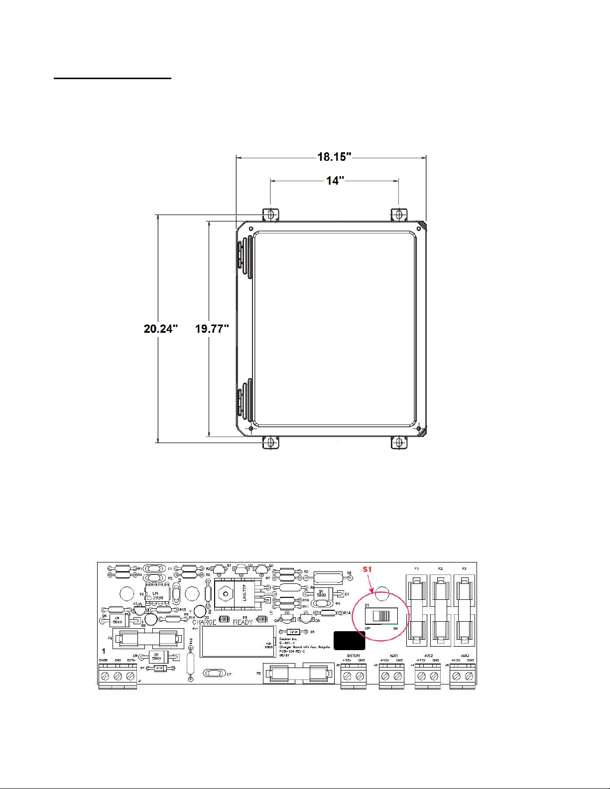
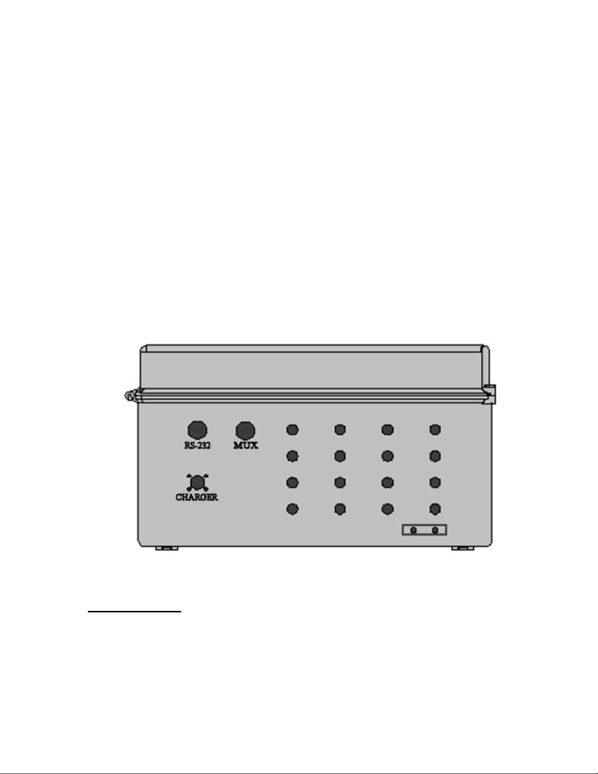
2. HARDWARE........................................................................................................................................................1
3. INSTALLATION....................................................................................................................................................2
3.1 TURNING ON POWER................................................................................................................................................2
3.2 EARTH GROUND ......................................................................................................................................................3
3.3 GAGES ...................................................................................................................................................................3
3.4 COMMUNICATIONS ..................................................................................................................................................3
4. SOFTWARE .........................................................................................................................................................3
5. BATTERY MAINTENANCE....................................................................................................................................4
5.1 AC POWER .............................................................................................................................................................4
5.2 SOLAR POWER.........................................................................................................................................................4
5.3 EXTERNAL BATTERY ..................................................................................................................................................4
5.4 BATTERY REPLACEMENT ............................................................................................................................................4
5.5 FUSES ....................................................................................................................................................................4
6. TROUBLESHOOTING ...........................................................................................................................................5
APPENDIX A. SPECIFICATIONS ................................................................................................................................7
A.1 CR800 MEASUREMENT AND CONTROL MODULE ..........................................................................................................7
A.1.1 Analog Inputs..............................................................................................................................................7
A.1.2 Excitation Outputs ......................................................................................................................................7
A.1.3 Pulse Inputs.................................................................................................................................................7
A.1.4 Control Ports ...............................................................................................................................................8
A.2 AVW200 VIBRATING WIRE INTERFACE (SEE AVW200 MANUAL FOR COMPLETE SPECIFICATIONS) ........................................8
A.3 MODEL 8032 MULTIPLEXER (SEE THE APPENDIX FCOMPLETE SPECIFICATIONS)...................................................................8
APPENDIX B. SHIP LIST ...........................................................................................................................................8
APPENDIX C. DATA STORAGE .................................................................................................................................9
C.1 INPUT LOCATIONS ....................................................................................................................................................9
C.2 DATA STORAGE .......................................................................................................................................................9
C.3 DATA STORAGE EXAMPLE........................................................................................................................................10
APPENDIX D. SYSTEM WIRING ............................................................................................................................. 11
D.1 CR800 WIRING (8025-2, 8025-3 AND 8025-4) ......................................................................................................11
D.2 AVW200 WIRING (8025-2, 8025-3 AND 8025-4) ..................................................................................................11
D.3. CR800 WIRING (8025-5).....................................................................................................................................11
D.4 RS-232 CONNECTOR WIRING .................................................................................................................................12
D.5 CHARGER WIRING .................................................................................................................................................12
D.6 CABLES ................................................................................................................................................................12
D.6.1 AC Charger (110VAC/220VAC)..................................................................................................................12
D.6.2 External Power Cable................................................................................................................................12
D.7 FUSES..................................................................................................................................................................13
D.8 MULTIPLEXER CONNECTOR WIRING ..........................................................................................................................13

APPENDIX E. LOGGERNET QUICK START GUIDE ................................................................................................... 14
E.1 OVERVIEW ........................................................................................................................................................... 14
E.2 GETTING STARTED ................................................................................................................................................. 14
E.2.1 Program Files............................................................................................................................................ 14
E.2.2 Connection Setup...................................................................................................................................... 14
E.2.3 Connecting to the Datalogger .................................................................................................................. 17
E.3 MODIFYING THE DATALOGGER PROGRAM.................................................................................................................. 18
E.3.1 Editing the CRBasic Program .................................................................................................................... 18
E.3.2 Uploading Files ......................................................................................................................................... 20
E.4 DATA HANDLING................................................................................................................................................... 23
E.4.1 Data Collection Configuration .................................................................................................................. 23
E.4.2 Live Monitoring ........................................................................................................................................ 24
E.4.3 Collecting Data ......................................................................................................................................... 25
APPENDIX F. 8032 MULTIPLEXER MANUAL .......................................................................................................... 26
F.1 THEORY OF OPERATION.................................................................................................................................... 26
F.2 MICRO-800/MICRO-1000 MODE OF OPERATION................................................................................................... 29
F.3 WIRING ............................................................................................................................................................. 30
F.4 MODEL 8032-27 AND LOAD CELL WIRING ................................................................................................................ 33
F.5 TROUBLESHOOTING ......................................................................................................................................... 34
F.6 SPECIFICATIONS................................................................................................................................................ 34
F.6.1 General ..................................................................................................................................................... 34
F.6.2 Relays........................................................................................................................................................ 34
F.6.3 Tripolar Plasma Surge Arrestor................................................................................................................. 35
F.6.4 Bipolar Plasma Surge Arrestor.................................................................................................................. 35
F.6.5 Inductor .................................................................................................................................................... 35
F.6.6 Transient Voltage Suppressor (Transorb) ................................................................................................. 35
F.6.7 Transducer Connection Maximum Operating Voltage Levels: ................................................................. 35
F.6.8 Reset and Clock Maximum Operating Voltage Levels: ............................................................................. 35
F.7 CONNECTOR AND CABLE WIRING..................................................................................................................... 36
F.8 DAISY CHAIN OPERATION ................................................................................................................................. 37
F.9 MAXIMUM 8032-5 (TAN CABLE) CABLE LENGTHS ............................................................................................ 39
F.10 MEMS SENSOR TO MULTIPLEXER WIRING...................................................................................................... 40
FIGURE 1-DIMENSIONS ................................................................................................................................................ 2
FIGURE 2-CHARGE REGULATION CIRCUIT BOARD....................................................................................................... 2
FIGURE 3-DATALOGGER CONNECTIONS ...................................................................................................................... 3

1
1. OVERVIEW
The MICRO-800 Datalogger is designed to support the reading of a large number of Geokon
Vibrating Wire Instruments for various unattended data collection applications through the use of
an internal Geokon Model 8032 Multiplexer. Weatherproof packaging allows the unit to be
installed in field environments where inhospitable conditions prevail. The Nema 4X enclosure
also has a provision for locking to limit access to responsible field personnel.
A basic datalogging system consists of the Campbell Scientific CR800 datalogger, an internal
multiplexer and an External Multiplexer port. Multiplexers expand the system by increments of
16 or 32 channels depending on the instrument type and configuration. The standard model
8025-2 Micro-800 datalogger can support one internal Multiplexer and external Multiplexer. The
External Multiplexer port can also be used to Daisy chain up to eight Multiplexers (please see
8032 Manual for more information). The standard model 8025-4 and 8025-5 dataloggers are
identical to the model 8025-2, but are configured for 32 VW gages only (8025-4) or 32
Thermistors only (8025-5). The standard model 8025-3 Micro-800 datalogger can support two
internal 16 channel Multiplexers and has 32 cable entries.
2. HARDWARE
The controller portion of the MICRO-800 datalogger consists of a Campbell Scientific CR800
Measurement and Control Datalogger. To gain an understanding on the workings and
capabilities of the CR800 it is necessary to read the Overview section of the CR800 Operator’s
Manual. The CR800 Operator’s Manual is available as a pdf file on the Campbell Scientific
Resource CD supplied with the datalogger.
A Campbell Scientific AVW200 Vibrating Wire Interface provides the required excitation and
signal processing for the vibrating wire sensors connected to the Datalogger. The AVW200 uses
spectral analysis to find the resonant frequency of the Vibrating Wire Gage. The AVW200 is
also used to measure the thermistor used in Geokon’s vibrating wire instruments. For complete
specifications of the AVW200 see the AVW200 Instruction Manual on the Campbell Scientific
Resource CD.
A dual-mode battery charging circuit board is used to provide the charging voltage for proper
maintenance of the installed lead acid battery. The circuit board contains fused protected
terminal blocks used to provide a nominal 12VDC supply for devices such as the CR800 and
Model 8032 Multiplexer board. In some cases a Solar Charge Regulator may be used in place of
the dual-mode charger.
The Model 8032 Multiplexer board expands the number of channels that can be read by the
MICRO-800 Datalogger. The channel switching is accomplished by mechanical relays mounted
on the underside of the circuit board and the transducer connections are accomplished by friction
locking terminals. Power, reset and clocking for the multiplexer are supplied by the MICRO-800.
The Model 8032 multiplexer can be configured for 16x4 or 32x2 channels depending on
application. Please see Appendix F for more information on the Geokon Model 8032
multiplexer.
A 12 volt, seven amp hour, lead acid battery is used to provide power for the datalogger. The
battery is provided to supply operating power for a limited period of time should the AC or solar
power, used to maintain the battery, be interrupted. Under normal operating conditions and
proper maintenance, the life expectancy of the battery is approximately five years.

2
3. INSTALLATION
The recommended method of installation involves attaching the enclosure (MICRO-800) to a
fixed structure, such as a wall, in an upright position (Figure 1). Mounting dimensions shown in
inches:
Figure 1 - Dimensions
3.1 Turning on Power
After the Datalogger is installed the charger can be plugged into the AC mains and the On/Off
switch S1 on the Charge Regulation circuit board switched to the “On”position (Figure 2). It is
recommended that the charger be left plugged in at all times (Section 5.1).
Figure 2 - Charge Regulation Circuit Board

3
3.2 Earth Ground
An earth grounding lug is supplied on the exterior of the Micro-800 enclosure to connect the
system to earth ground (Figure 3). A grounding rod can be driven (or other suitable attachment to
earth utilized) to ground the system and provide a path to earth for protection against a lightning
strike or other transient voltage. A 6’to 8’copper grounding rod connected to the Dataloggers
grounding lug with a large gauge wire (12 AWG or larger) is recommended. The earth ground
connection should be made as close to the Datalogger as possible.
3.3 Gages
At this time the vibrating wire sensors can be connected to the multiplexer. Please refer to
Appendix F for the appropriate connection description.
3.4 Communications
Standard communications with the Datalogger is established by connecting the supplied serial
cable to the RS-232 port (Figure 3) and the COM port on a computer, or a USB port on the
computer by using the provided USB to Serial converter cable.
Figure 3 - Datalogger Connections
4. SOFTWARE
The Micro-800 Datalogger is operated by a download file that is generated by a software
program. The software package the MICRO-800 Datalogger may be supplied with is either
MultiLogger software (developed by Canary Systems, Inc., New London, NH) or LoggerNet
software (developed by Campbell Scientific, Logan, Utah). Please refer to the manual supplied
with the software for instructions on installing the software and creating the required download
file for datalogger operation.

4
5. BATTERY MAINTENANCE
5.1 AC Power
The MICRO-800 is supplied with an external AC to DC power supply for maintaining the charge
of the battery and providing power to the Datalogger and peripherals. It is imperative that the
power supply remain connected to the Datalogger as the battery installed in the Datalogger is
only provided as a temporary source of power should the power supply be disconnected or mains
power interrupted. Actual run time solely on battery power will vary for each datalogging
system, depending on the hardware configuration and sensor scan interval. If the battery voltage
drops below 9.6 volts operation of the Datalogger will become erratic as evidenced by
communication problems and possible improper measurements.
5.2 Solar Power
If AC mains power is not available, a properly sized solar panel can be used to provide power to
maintain the charge state of the battery and provide power to the Datalogger and peripherals. The
size of the solar panel is determined by geographic location of the Datalogger, hardware
configuration, and the sensor scan interval.
5.3 External Battery
Additionally, a large external battery, such as a deep cycle marine battery, may be connected to
the Datalogger via the supplied external power cable to provide power to the Datalogger and
peripherals. When this type of battery is connected to the Datalogger the internal Datalogger
battery is automatically disconnected from the system to prevent parasitic drain on the external
battery.
5.4 Battery Replacement
If the internal Lead Acid Battery has failed it is recommend that the unit be returned to the
factory for service by Geokon personnel. However, with skilled personnel and appropriate tools,
it is possible for the user to replace the battery. Consult the factory for information.
5.5 Fuses
There are five fuses on the dual mode charger board of the MICRO-800 (Figure 2). Once
removed and with the power switch off, a fuse can be checked visually and with an ohmmeter. A
gap may be evident (with some discoloration) if the fuse needs replacing. This can be verified by
a high resistance measurement (megaohms) with an ohmmeter. If fuse needs replacing, insert
one of the supplied replacement fuses. If there are no replacement fuses available, consult the
factory or they can be purchased from an electrical supply house. All five fuses are two amp
SLO-BLO 5x20 mm. Consult Appendix D.7 for fuse assignments.

5
6. TROUBLESHOOTING
This section will NOT attempt to cover all possible problems that could be encountered in the
course of Datalogger operations. Consult the factory if other problems arise or remain
unresolved.
Cannot communicate with the Datalogger.
Suggestions:
1. The wrong communication cables are being used or the cables in use are defective.
Consult Appendix D.3 to verify cable pinout. Consult the factory for interfacing information.
2. The internal battery could be dead. Charge overnight and try again. If it still doesn’t work
check the voltage across the terminals of the battery. If the voltage is still below 10 volts the
battery may need to be replaced.
3. The wrong communication port is being used on the host computer (default is COM1).
Consult the appropriate software manual for instructions on changing the communication port.
4. The communication port on the host computer is defective. Verify the functioning and
configuration of the COM port by using it with another RS-232 device, such as a modem or
serial printer.
5. The Datalogger Auxiliary Fuse on the Dual-Mode Charger board is blown. Refer to
Appendix D.7 for proper fuse replacement.
The system battery voltage and panel temperature read odd numbers.
Suggestions:
1. The system battery could be low. Charge and check again (see previous section).
2. A disruptive current loop may be operating as a result of improper grounding or
excessive noise. Consult the factory for more information.
The internal battery measurement does not increase and charging LED (Yellow =
Charging and Green = Charged) does not light when the AC adaptor is plugged in.
Suggestions:
1. The adaptor may be damaged. Check the output pins of the adaptor with a voltmeter.
2. The charger fuse is blown. Consult Section 5.5 for checking and/or replacement.
3. The internal battery is no good. Consult the factory.

6
The Datalogger will not operate on external power.
Suggestions:
1. The external voltage supply is below operating limits. If the external source is a battery,
charge it. If it’s a power supply, check the output with a voltmeter.
2. The external power or battery fuse is blown (Section 5.5).
Loss of CR800 program and/or data.
Suggestions:
1. The system has experienced a voltage dropout or surge which disrupted operations.
2. The surge originated as a result of lightning. Install appropriate grounding. Install
lightning protection devices on all incoming and outgoing lines (consult factory).
Sensor readings show -99999 or are unstable.
Suggestions:
1. The wrong sensor type has been selected. Check the model number of the sensor against
the software setting (Section E.1).
2. The cable(s) to the sensor(s) have been damaged permitting moisture and debris to enter
the jacket. Wires may be shorted together. Inspect the cable.
3. If all sensors on a particular multiplexer are erratic or returning “-99999”perhaps the
multiplexer or interface cable has been damaged / unplugged.
4. The sensor(s) have been damaged. For example, overrange on a vibrating wire sensor can
cause erratic readings.
5. There is an electrical noise source nearby. Move the sensor, cables, and Datalogger away
from the noise source. Install grounding devices. Consult the factory.
The sensor readings show OVERRANGE all the time.
Suggestions
1. The “Sensor Type”selected for that particular channel is “None”. This is applicable for
users of MultiLogger (Section E.1). Please refer to the MultiLogger manual.
2. A scan has not been initiated yet because of the “Start Time”setting (MultiLogger users
only).
3. “Update”has not been run (MultiLogger users only).

7
APPENDIX A. SPECIFICATIONS
A.1 CR800 Measurement and Control Module
Power requirements: 9.6 to 16 VDC
Analog measurement current drain: 27.6 mA
Processing current drain: 16.2 mA
Quiescent current drain: .6 mA
Operating temperature: -25
to +50
C
Processor: Hitachi H8S 2322
Memory: 2Mb ROM, 4Mb RAM
Storage capacity: 2,000,000 Final Storage Locations
Real time clock accuracy:
3 minutes per year
Expansion capability: up to 2 x 32 channel multiplexers (single ended)
System battery: 12 V, 7 Ahr lead acid
Communication: RS-232 115200 baud, eight data bits, no parity, one stop bits
A.1.1 Analog Inputs
Configuration: Three differential or six single-ended
Voltage measurement accuracy: 0.06% of FSR for 0
to 40
C
Voltage measurement ranges and resolution:
Range
Resolution
5.0 V
1330 V
2.5 V
667 V
250 mV
66.7 V
25 mV
6.7 V
7.5 mV
2 V
2.5 mV
.67 V
Common mode range:
5 VDC
DC common mode rejection (CMRR): >100 dB
Maximum input voltage: 16 VDC
A.1.2 Excitation Outputs
Configuration: Two switched output channels
Excitation range:
2.5 V
Excitation resolution: 0.67 mV
Excitation accuracy: 0.06% of FSR for 0
C to 40
C
Output current: 25 mA @ 2.5 VDC
A.1.3 Pulse Inputs
Configuration: two 24 bit
Maximum count rate: 16.7x10^6
Maximum input voltage: ±20 VDC
Modes: Switch closure, high frequency pulse, low level AC

8
A.1.4 Control Ports
Configuration: Four digital I/O ports
Input/output resistance: 100k
/330
, respectively
Input “high”level: 3.8 V to 5.3 V
Input “low”level: -0.3 V to 1.2 V
Output “high”level: 5 V
0.1 V
Output “low”level: <0.1 V
A.2 AVW200 Vibrating Wire Interface (See AVW200 Manual for complete
specifications)
Power requirements: 9.6-16 VDC
Vibrating Wire measurement current: 25 mA
Quiescent current: .3 mA
A.3 Model 8032 Multiplexer (See the Appendix F complete specifications)
APPENDIX B. SHIP LIST
The following equipment is included with the system:
External Power cable
DB-9 to 10 pin Bendix RS-232 Cable
USB to RS-232 Adapter
Small regular screwdriver
Five spare slo-blo, two amp fuses
AC Adaptor (110 VAC or 220 VAC)
The following manuals are included:
MICRO-800 Instruction Manual
Campbell Scientific Resource disk
Optional accessories:
COM220 Landline Phone Modem with manual (access Datalogger via phone line)
Cellular Phone Modem with manual
Short Haul Modems with manual (current loop communication device)
MD485 RS-485 Multidrop Interface with manual (Datalogger networking)
Solar Panel with mounting hardware, charger, and manuals
RF Modem with manuals (wireless Datalogger communication)
Consult the factory for additional information on any of the optional accessories.

9
APPENDIX C. DATA STORAGE
C.1 Input Locations
Default explanations for the Input/Final Storage location usage in MultiLogger unless user
configured:
Input Storage #
Label
Explanation
1
Logger ID
Datalogger ID 1-9999
2
Year
Year when last readings taken
3
JulianDay
Julian Day (1-365) when last readings taken
4
Time-HHMM
Time (24 hour) when last readings taken
5
Seconds
Seconds when last readings taken
6
DecimlDay
Decimal Day when last readings taken
7
ElapsdHr
Elapsed Hours from “Start”
(if “Log”selected as “Scan Interval”)
8
ElapsdMin
Elapsed Minutes from “Start”
(if ”Log”selected as “Scan Interval”)
9
ElapsdSec
Elapsed Seconds from “Start”
(if “Log”selected as “Scan Interval”)
10
Battery
Datalogger battery voltage
11
PanelTemp
Datalogger panel temperature (°C)
47-78
Mx1
Readings from Gages on Mux #1
C.2 Data Storage
Total Arrays of Data that can be stored per 16 Channel Multiplexer. Each array contains all Data
stored at each read interval.
Total Arrays
1 Multiplexer Array Storage
20,700
2 Multiplexer Array Storage
12,257
3 Multiplexer Array Storage
8,686
4 Multiplexer Array Storage
6,701
5 Multiplexer Array Storage
5,457
6 Multiplexer Array Storage
4,593

10
C.3 Data Storage Example
If data is stored once a minute:
Minutes
Hours
Days
Total Arrays
1 Multiplexer Overwrite Time:
20,685
344.8
14.4
20,700
2 Multiplexer Overwrite Time:
12,244
204.1
8.5
12,257
3 Multiplexer Overwrite Time:
8,722
145.4
6.1
8,686
4 Multiplexer Overwrite Time:
7,633
127.2
5.3
6,701
5 Multiplexer Overwrite Time:
5,450
90.8
3.8
5,457
6 Multiplexer Overwrite Time:
4,586
76.4
3.2
4,593
If data is stored once an hour:
Minutes
Hours
Days
Total Arrays
1 Multiplexer Overwrite Time:
1,241,454
20,690.9
862.1
20,700
2 Multiplexer Overwrite Time:
735,407
12,256.8
510.7
12,257
3 Multiplexer Overwrite Time:
521,196
8,686.6
361.9
8,686
4 Multiplexer Overwrite Time:
403,022
6,717.0
279.9
6,701
5 Multiplexer Overwrite Time:
327,413
5,456.9
227.4
5,457
6 Multiplexer Overwrite Time:
275,573
4,592.9
191.4
4,593
If data is stored once a day:
Minutes
Hours
Days
Total Arrays
1 Multiplexer Overwrite Time:
29,795,034
496,583.9
20,691.0
20,700
2 Multiplexer Overwrite Time:
17,650,067
294,167.8
12,257.0
12,257
3 Multiplexer Overwrite Time:
12,507,876
208,464.6
8,686.0
8,686
4 Multiplexer Overwrite Time:
9,651,092
160,851.5
6,702.1
6,701
5 Multiplexer Overwrite Time:
7,858,073
130,967.9
5,457.0
5,457
6 Multiplexer Overwrite Time:
6,613,913
110,231.9
4,593.0
4,593

11
APPENDIX D. SYSTEM WIRING
D.1 CR800 Wiring (8025-2, 8025-3 and 8025-4)
CR800
Connections
MUX 1
Interface
Cable
MUX 2
Interface
Cable
AVW200 SDI-
12
Interface Cable
CR800
Power
Cable
Description
AG
Green & Black
Green & Black
NC
NC
Analog Ground
12V
Blue
Blue
NC
NC
12 VDC Output
G
Violet
Violet
Blue’s Black
NC
Ground
C1
Gray
NC
NC
NC
Digital I/O Port 1 / RESET
C2
NC
Gray
NC
NC
Digital I/O Port 2 / RESET
C3
NC
NC
Blue
NC
Digital I/O Port 3 /
SDI-12 Communication
C4
White
White
NC
NC
Digital I/O Port 4 / Clock
PWR In +12V
NC
NC
NC
Red
+12VDC Power
PWR in G
NC
NC
NC
Black
Power Ground
D.2 AVW200 Wiring (8025-2, 8025-3 and 8025-4)
AVW200
Connections
Color
MUX Interface
Ribbon Cable
CR800
Datalogger
Description
1V +
Brown
Conductor 1
NC
Vibrating Wire +
1V -
Red
Conductor 2
NC
Vibrating Wire -
1T+
Orange
Conductor 3
NC
Thermistor +
1T-
Yellow
Conductor 4
NC
Thermistor -
SCI12
Blue
NC
C3
SDI-12 Communications
G
Blue’s Black
NC
G
Ground
12V
Red
NC
12V
+12VDC Power
G
Red’s Black
NC
G
Ground
D.3. CR800 Wiring (8025-5)
CR800
Connections
MUX 1
Interface
Cable
MUX 2
Interface
Cable
CR800 Power
Cable
Description
AG
Green &
Black
Green & Black
NC
Analog Ground
12V
Blue
Blue
NC
12 VDC Output
G
Violet
Violet
NC
Ground
C1
Gray
NC
NC
Digital I/O Port 1 / RESET
C2
NC
Gray
NC
Digital I/O Port 2 / RESET
C4
White
White
NC
Digital I/O Port 4 / Clock
*VX1
Brown
Brown
NC
Excitation 1 /Thermistor +
*SE2
Red
Red
NC
Single Ended Channel 2 /
Thermistor -
PWR In +12V
NC
NC
Red
+12VDC Power
PWR in G
NC
NC
Black
Power Ground

12
* NOTE: The Thermistor is read using Single Ended Channel 2 and Excited with VX1
through a bridge completion circuit.
D.4 RS-232 Connector Wiring
10-Pin Bendix
Color
Description
A
White
Ground
B
Green
Transmit
C
Orange
Receive
D
Yellow
RTS
E
Blue
CTS
G
Violet
DTR
D.5 Charger Wiring
Pin
Description
Wire Color
A
Charger + (14-22 VDC Input)
Grey
B
Ground
Blue
C
Battery + (12 VDC Output)
Violet
D.6 Cables
D.6.1 AC Charger (110VAC/220VAC)
Pin
Description
Condor - Wire Color
A
Charger + (14-22 VDC Input)
Black with White Stripe
B
Ground
Black
D.6.2 External Power Cable
Pin
Description
Wire Color
Clip
A
No Connection
No Connection
No Connection
B
Ground
Black
Black
C
Battery + (12 VDC)
Red
Red

13
D.7 Fuses
Fuse
Description
F1
12VDC Auxiliary 1
F2
12VDC Auxiliary 2
F3
12VDC Auxiliary 3
F4
External Battery
F5
Battery
D.8 Multiplexer Connector Wiring
10-Pin
Bendix
Color
Description
A
Brown
Vibrating Wire +
B
Red
Vibrating Wire -
C
Orange
Thermistor +
D
Yellow
Thermistor -
E
Green
Analog Ground
F
Blue
+12 VDC
G
Violet
Ground
H
Grey
MUX Reset
J
White
MUX Clock
K
Black
Analog Ground

14
APPENDIX E. LOGGERNET QUICK START GUIDE
E.1 Overview
Campbell Scientific’s LoggerNet Software is used to communicate with the Datalogger, program
user specific settings and collect Data stored in the Datalogger memory. LoggerNet is designed
to be used with Geokon Micro-1000 and Micro-800 Dataloggers reading Vibrating Wire and
MEMS tilt sensors. Other configurations and sensor outputs are available upon request. Geokon
provides the user with a generic Start Program to simplify acquiring Data without the need to be
proficient in Campbell Scientific CRBasic programming code. The Start Program(s) will be
preconfigured with a default Scan Interval and will store Raw Units by default. Each Start
Program will have two associated files on the factory supplied USB flash drive. The first is the
Main CRBasic program (.CR1/.CR8) and includes all programming code required to read and
store Data according to the Datalogger configuration. The Main CRBasic program does not
require modification by the user in most cases. The second file is the Include (.DLD) text file and
is used by the Main program to import user specific parameters. The Include File allows program
parameters such as the Scan Interval, Zero Readings, Linear Gage Factors, Data File Header
Labels and Temperature Correction factors to be modified by the user.
E.2 Getting Started
E.2.1 Program Files
After installing LoggerNet, the CRBasic program files are located on the Geokon USB
Thumb Drive. The file types are “.DLD” and “.CR1”/“.CR8.”, these files should first be
copied to the end users computer in C:\Campbellsci\CRBasicEditor.
E.2.2 Connection Setup
The Launch Menu provides a drop-down list of all the categories on the LoggerNet
toolbar. Hovering over a category will display a list of applications related to that
category.
With the Launch Menu open, hover over “Main” and press “Setup” from the resulting list
of applications.
This manual suits for next models
1
Table of contents
Other Geokon Other manuals
Popular Other manuals by other brands

Central Machinery
Central Machinery 40612 Set up and operating instructions

Sony
Sony STR-DE997 - Fm Stereo/fm-am Receiver operating instructions

Quest Engineering
Quest Engineering CDG 114 Installation, operation and maintenance instructions

MadgeTech
MadgeTech TransiTempII-RH user guide

ReelCraft
ReelCraft T-1115-08 operating instructions

Summit
Summit SBC58B Series instruction manual