x1 - T15 L-Key x1 - PHILLIPS HEAD L-KEY x2 - INSTALL SCREWS
x2 - BASE STAND
U-CLIP
2” BASE STAND l SUPPORT DE BASE 5,8 cm l SOPORTE DE LA BASE DE 5,8 cm
SKU: STAND-ASM-PART
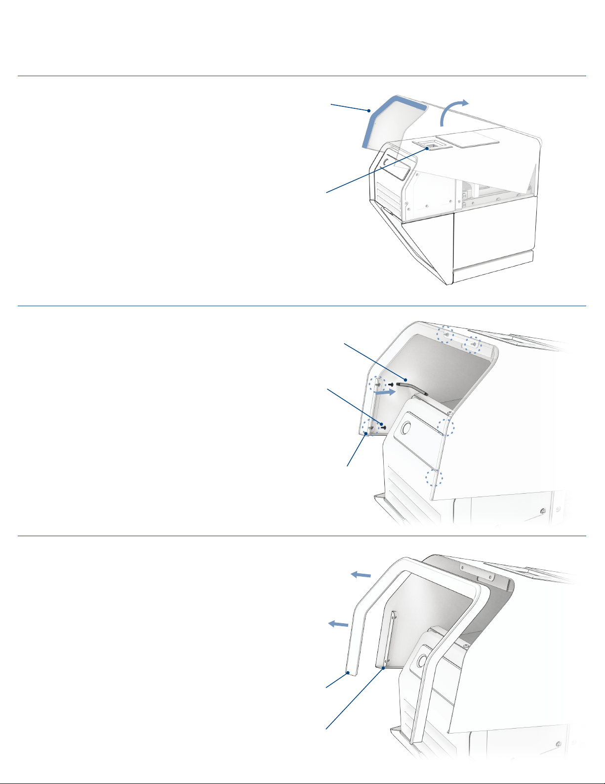
Needed for attaching the Cup Guide, also
elevates unit up by 2” (installation page 2)
Nécessaire pour fixer le guide de coupelle,
élève également l'unité de 5,8 cm
(Installation, page 2)
Necesario para fijar la guía para vasos,
también eleva la unidad 5,8 cm (página 2 de
la instalación)
CUP GUIDE l GUIDE DE COUPELLE l GUÍA PARA VASOS
SKU: FUNNEL-ASM-PART
Helps users position and guide their cup into
the sealing chamber (installation page 3)
Aide les utilisateurs à positionner et guider
leur coupelle dans la chambre de scellage
(Installation, page 3)
Ayuda a los usuarios a colocar y saber
posicionar su vaso en la cámara de sellado
(página 3 de la instalación)
FRONT DISPLAY COVER l CAPOT D'AFFICHAGE
AVANT l CUBIERTA DE LA PANTALLAFRONTAL
SKU: INST-PLT-ASM-PART
Displays instructions for how to use the
machine. (Installation page 4-5)
Ache les instructions sur l'utilisation de la
machine. (Installation, page 4 à 5)
Muestra las instrucciones de uso de la
máquina (páginas 4-5 de la instalación)
Screws and L-Keys needed for label plate install.
Optional hook spacers for the cup guide.
Vis et clés coudées nécessaires pour l'installation
de la plaque signalétique. Entretoises de crochet
en option pour le guide de coupelle.
Tornillos y llaves Allen necesarios para la instalación
de la placa de identificación. Separadores de
gancho opcionales para la guía para vasos.
UNIT ACCESSORIES
INSTALLATION KIT
1
INSTALLATION TOOLS AND COMPONENTS l OUTILS ET COMPOSANTS
D'INSTALLATION l HERRAMIENTAS Y COMPONENTES DE LA INSTALACIÓN
FRONT BACK
FRONT BACK
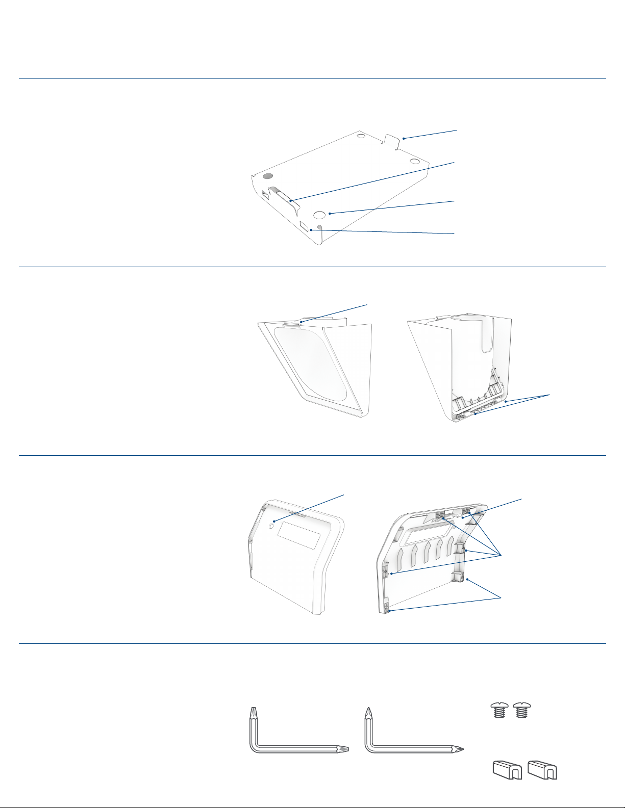
BACK ALIGNMENT TAB
TOP SNAP
FEATURE
POWER BUTTON
ACCESS HOLE
SCREW ATTACHMENT
LOCATIONS
FRONT ALIGNMENT TAB
GUIDE
HOOKS
FRONT SNAP TAB
FOOT HOLES
CUP GUIDE HOOK HOLES
ALIGNMENT POSTS