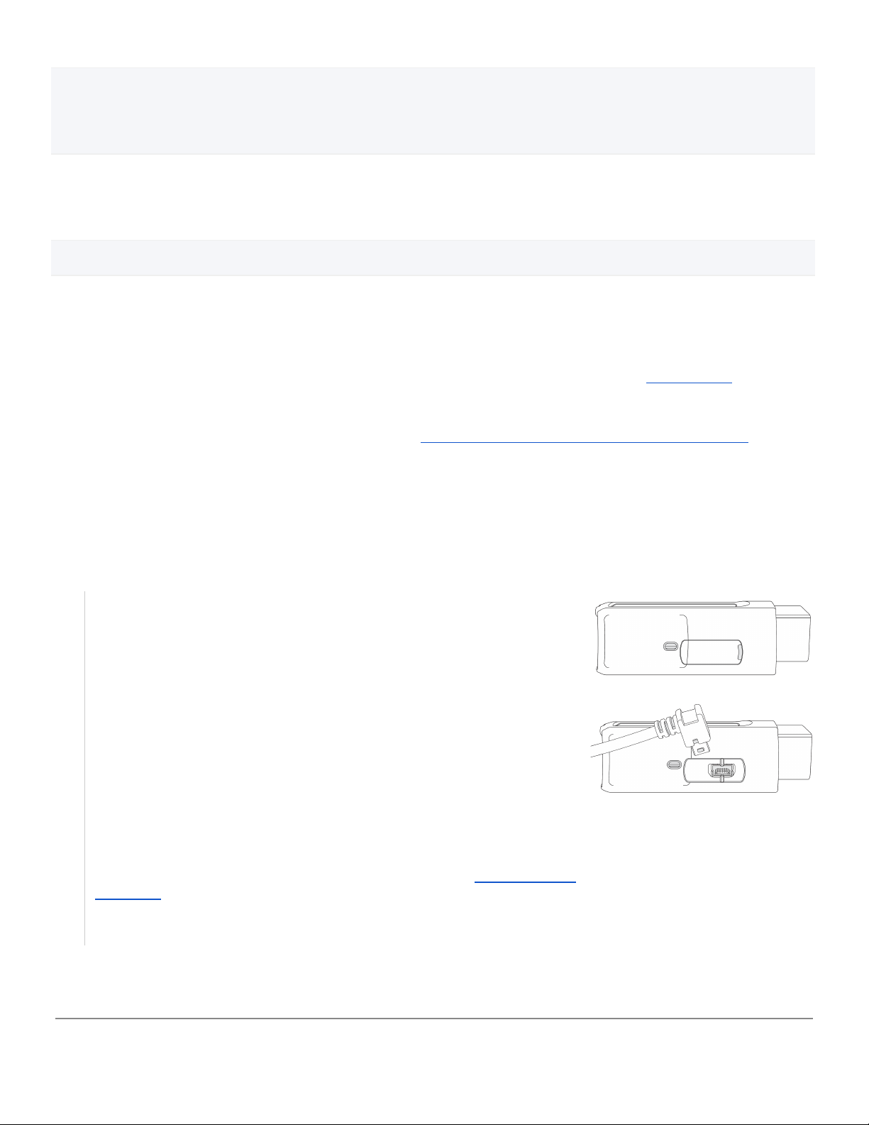
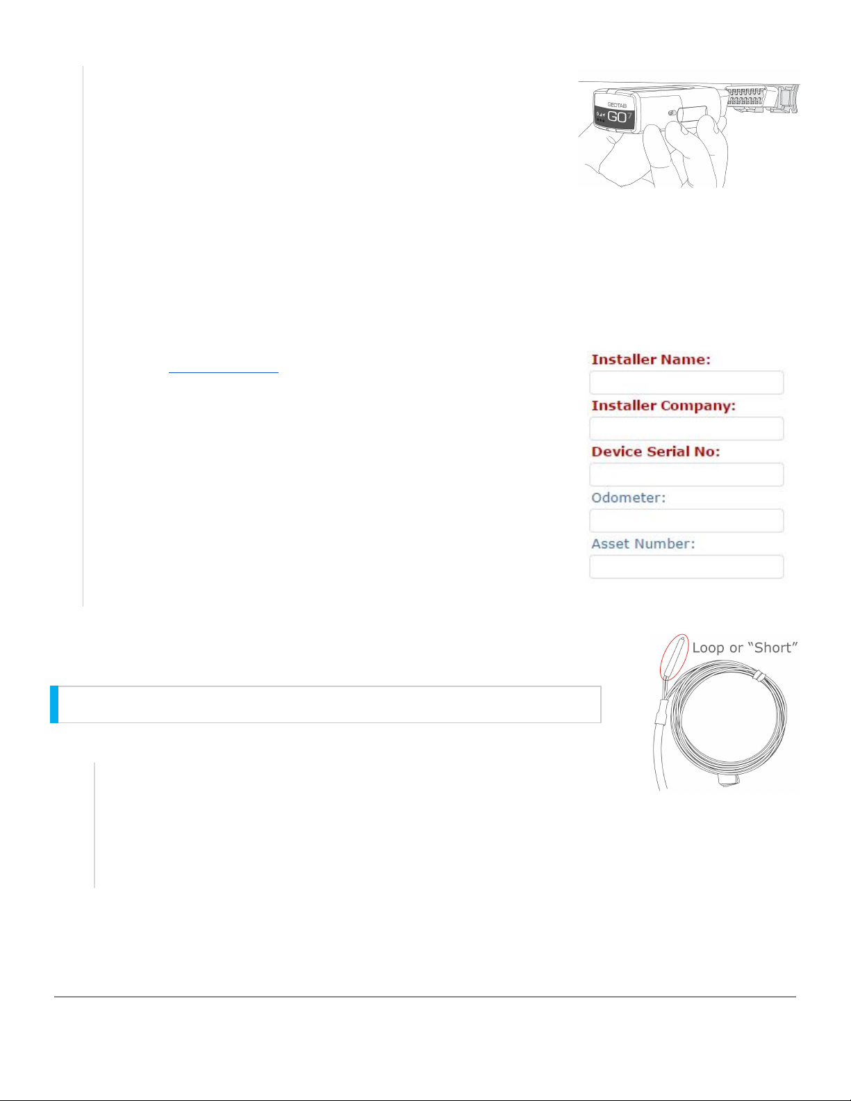
Geotab IOX-AUXM User manual

IOX-AUXM
For the most up to date version, please visit: goo.gl/srUWJY
The IOX-AUXM monitors up to eight signals from your vehicle in real-time —
providing additional insight into the condition of your fleet.
Top Features
●Monitor up to 8 inputs at any time with two IOX-AUXMs
●Self-learning input triggers
●Supports GND–Float, GND–Driven, and Float–Driven circuits
IOX Hardware Technical Specifications
Weight
50 g
Size
Overall length: 1100 mm L
Widest point: 36 mm W × 16 mm H
Housing
Black, moisture-resistant thermoplastic overmold
Interfaces
CAN: 500 kbps (for daisy chaining)
Inputs Available
AUX1, AUX2, AUX3, AUX4 or AUX5, AUX6, AUX7, AUX8
Input Absolutes
−40 V to +40 V
Resistance
Input Impedance of each AUX: 30.3 kΩ to 37 kΩ
Driving Circuit Resistance must be less than 100 Ω
Input Logic Levels
GND — Float, Low: Floating, High: <100 mV
Float — Driven, Low: Floating, High: >3.3 V
GND — Driven, Low: <100 mV, High: >3.3 V
Input Type Detection
Automatically identifies GND-Float, Float-Driven and GND-Driven driving circuits with
capacitive loading of <200pF
Power Output
Daisy Chaining: 2500 mA @ 12 V/24 V
Current Rating
Operating Mode: 30 mA
Sleep Mode: 0.4 mA
Temperature Rating
−40 ℃ to +85 ℃
Copyright © Geotab Inc. 2015-2019 - All Rights Reserved | www.geotab.com | Rev 2.11 - 11/2019
® denotes a trademark of Geotab Inc., registered in Canada, the United States and other countries
1

IOX Installation Instructions
NOTE: Professional Installation Required — Installation of the IOX-AUXM requires the installer to have sufficient technical
knowledge and expertise for mobile device installation and integration into modern vehicles, i.e. Certified Geotab®Installer
certification or equivalent.
WARNING! Prior to IOX-AUXM installation, read and follow GO device installation instructions (goo.gl/rkLRiA) to verify any
existing GO device installation is correct in preparation for IOX-AUXM installation. Incorrect installation of either the GO
device, and/or IOX-AUXM can result in loss of vehicle control and serious injury.
WARNING! Prior to IOX-AUXM installation, read and follow Important Safety Information and Limitations of Use, located at
the end of the document. Always read and follow all safety information to prevent loss of vehicle control and serious
injury.
Identify and test the connection points for the auxiliaries you wish to monitor. Please note, the IOX wire has a reach of
approximately 3.5 feet from the GO Device mounting location. Extending the wiring to reach some connection points may
be necessary. Make the auxiliary connections and secure them using an approved method, such as T-tapping. Ensure
none of the components or wiring interferes with the safe operation of the vehicle.
How to Install IOX-AUXM
Connectors
8-pin Molex 43020-0800
Keyed 5-pin mini-USB type-B plug: Daisy chain power and CAN in
Keyed 5-pin mini-USB type-B socket: Daisy chain power and CAN out
Installation
Keyed mini-USB plug connects to the GO device or another IOX
Input wires connect to the intended circuit
Wires covered by heat shrink must be cut for IOX to operate as AUX 5 to 8
Compatible Devices
GO6®, GO7®, GO7 Rugged, GO8®, GO8 Rugged, GO9®
1
Unplug the GO device from the vehicle and remove the IOX expansion port
cover on your GO device.
2
Plug the 90° USB connector from the IOX in to the GO device. Secure the
USB connector using a zip tie. Please note that over tightening the zip tie
may damage the USB connector.
Note: Insert the USB connector in the orientation displayed in the image.
3
The IOX-AUXM has four inputs — configured and labelled Aux 1–4. Connect
the desired auxiliaries in the vehicle to the IOX-AUXM wires, as needed. If
more than four auxiliaries are required please refer to Expanding your
IOX-AUXM.
Aux 1 = Blue Aux 2 = Orange Aux 3 = Green Aux 4 = White
Copyright © Geotab Inc. 2015-2019 - All Rights Reserved | www.geotab.com | Rev 2.11 - 11/2019
® denotes a trademark of Geotab Inc., registered in Canada, the United States and other countries
2

Expanding your IOX-AUXM
The IOX-AUXM can expand from four to eight auxiliaries by plugging in a second IOX-AUXM to
the expansion port of the first and following the steps below.
In order for the second IOX-AUXM to report as 5-8, follow the steps below:
Colour Guide
4
Once you connect the IOX-AUXM to the GO device, plug in the GO device and
immediately start the vehicle. The GO device will enter debug mode.
5
While the GO device is in debug mode, trigger each auxiliary one at a time so
the IOX-AUXM learns the inputs. Once the IOX-AUXM learns an input, the GO
device emits a number of beeps corresponding to the auxiliary number. For
proper configuration, you must hear the beeps when the auxiliaries are
triggered both ON AND OFF (e.g. Aux 2 sounds two beeps when triggered
ON and then two beeps when triggered OFF). Repeat this step until the
corresponding beeps are heard on BOTH trigger ON and trigger OFF.
6
Navigate to installmygps.com to verify that the device is communicating. In
the space provided, enter your name, the company name, and the GO device
serial number — found at the bottom of the device. Click Log Install.
7
After you click Log Install, the web page displays the current communication
status — in GREEN or RED text. If the device is communicating, the status is
displayed in GREEN text. If the device is not communicating, the status is
displayed in RED text.
Note:If the device is not communicating, please ensure the device is
installed correctly and try again.
Note: You must remove the zip tie from the original IOX-AUXM.
1
Locate the red and black loop, also known as Short.
2
Cut the wires to configure the IOX-AUXM to act as Aux 5-8.
3
Secure both IOX-AUXMs with a zip tie.
Copyright © Geotab Inc. 2015-2019 - All Rights Reserved | www.geotab.com | Rev 2.11 - 11/2019
® denotes a trademark of Geotab Inc., registered in Canada, the United States and other countries
3

Termination Shunt
The IOX comes with a termination shunt installed in the expansion port. If you plan to install more than one IOX in a daisy
chain, you must remove the shunt from each device in the line, with the exception of the last IOX connected. The shunt
must remain in the last IOX and secured with a zip tie.
The shunt in the last IOX ensures the GO device detects and configures the IOX, as effectively as possible.
Important Safety Information and Limitations of Use
For the latest version of Limitations of Use, please visit: goo.gl/k6Fp0w.
WARNING! Do not attempt to install, configure or remove any product from any vehicle while the vehicle is in motion or
otherwise in operation. All installation, configuration or removal must be done only in stationary vehicles which are
securely parked. Attempting to service units while being operated could result in malfunctions or accidents, leading to
death or serious personal injury.
WARNING! All in-vehicle devices and related cabling must be securely fastened and kept clear of all vehicle controls,
including gas, brake and clutch pedals. You must inspect devices and cabling on a regular basis to ensure all devices and
cabling continue to be securely attached. Loose cabling or devices may impede the use of vehicle controls, resulting in
unanticipated acceleration, braking or other loss of vehicle control, which could lead to death or serious personal injury.
Improperly fastened in-vehicle devices may detach and impact operators upon sudden acceleration or deceleration, which
may cause injury.
WARNING! If at any point after an in-vehicle device is installed a warning light illuminates on the vehicle dash or the
vehicle stalls or has a marked drop in performance, shut off the engine, remove the device, and contact your reseller.
Continuing to operate a vehicle with these symptoms can cause loss of vehicle control, and serious injury.
WARNING! Your in-vehicle devices must be kept clear of debris, water and other environmental contaminants. Failure to
do so may result in units malfunctioning or short-circuiting that can lead to a fire hazard or vehicle damage or serious
injury.
WARNING! Do not attempt to remove the devices from the vehicle in which they are originally installed for installation in
another vehicle. Not all vehicles share compatibility, and doing so may result in unexpected interactions with your vehicle,
including sudden loss of power or shutdown of the vehicle’s engine while in operation or cause your vehicle to operate
poorly or erratically and cause death or serious injury and/or vehicle damage.
NOTICE — This product does not contain any user-serviceable parts. Configuration, servicing, and repairs must only be
made by an authorized reseller or installer. Unauthorized servicing of these products will void your product warranty.
Aux 5 = Blue
Aux 6 = Orange
Aux 7 = Green
Aux 8 = White
Note:By cutting the loop, the second IOX-AUXM always report as AUX 5-8, regardless of whether or not an Aux 1-4 is
installed. The loop must be cut before connecting the IOX to the chain.
Note:Failure to install the shunt in the last IOX may affect IOX communication.
To ensure the IOX communicates, please secure the shunt with a zip tie.
Copyright © Geotab Inc. 2015-2019 - All Rights Reserved | www.geotab.com | Rev 2.11 - 11/2019
® denotes a trademark of Geotab Inc., registered in Canada, the United States and other countries
4
Table of contents
Other Geotab Automobile Accessories manuals
Popular Automobile Accessories manuals by other brands

AMiO
AMiO SSR-01L user manual

SuperATV
SuperATV DOOR-P-RAN900-001 installation instructions

Prorack
Prorack K367 Fitting Instructions for Basic Carrier

Ecco
Ecco 3735 Series Installation and operation instructions

ULTIMATE SPEED
ULTIMATE SPEED UASB 12 A1 operating instructions

Xblitz
Xblitz Mirror 2016 user manual