Geovent PM-180-1 User manual

Version 1.0 07.11.19
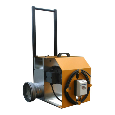
MOBILE FAN
PM-180-1
INSTRUCTION MANUAL
www.geovent.com.pl

2

3
Contents
1.0 General safety regulations .................................... 3
1.1 Dangers ............................................................... 3
1.2 Field of application ................................................ 3
1.3 Technical data ...................................................... 3
1.4 Construction ........................................................ 5
2.0 Installation ............................................................ 5
3.0 User instruction ..................................................... 8
4.0 Maintenance ......................................................... 9
5.0 Liability .................................................................. 9
6.0 Declaration of conformity..................................... 10
1.0 General safety precautions
IMPORTANT - Please study all the instructions before
mounting and use.
Please keep these instructions in a safe place and in-
struct all users in the function and operation of the pro-
duct.
Do not dismantle any factory-mounted parts, since it im-
pedes the commissioning of the equipment.
1.1 Danger
Explosive media – The fan is not suitable for the extraction
of aluminium dust, flour, textile dust nor for saw dust or
other media, which are connected with danger of explo-
sion, without specific approval from Geovent A/S.
Removing the protection net on the fan whilst in operati-
on involves a risk of mutilation.
Always switch off the current when mounting something
on the fan or when servicing it.
1.2 Field of application
The Geovent transportable fan PM-180 is typically used
for comfort ventilation as well as for smaller process
extraction jobs, where only a low pressure is required.
The fan is used for process extraction within the industry
for the extraction of welding smoke, vapours, and other
jobs where a fixed installation is not possible.
GEOVENT PM 180 may NOT be started without
the hose mounted, since this may result in motor
overload.
1.3 Technical data
Temperature extracted air Max. 100°C
Temperature surroundings Max. 40°C
Fans 2.800 min-1, noise emission to the surroundings
Type Lp, dB(A) Lp, 1m
PM-180 74 68
The noise level depends on various factors under vari-
ous circumstances. For instance, where in the room the
fan is installed, the size of the room, the temperature in
the room, the sound of the room and also the connection
(hose><pipe) of the fan.
The actual ampere consumption and the kW of the mo-
tor are shown on the metal sign on the fan.
Graphs showing the pressure drop of the fan
The air flow depends on the hose – whether it stretched
out or not.
ø125mm hose 600-700m³/h.
ø160mm hose 800-1.100 m³/h.
1.4 Construction
Fan housing: 100% hot-galvanized steel for optimal
corrosion resistance. Carrying feet have been mounted
on the fan with fitted vibration dampers as well as an
inlet nozzle with safety net.
Fan wheel: Forward curved sirocco-fan wheel (Fwheel)
in hot-galvanized steel sheet.
100
150
Volumenstrøm [m³/h]
Tryktab [Pa]
Ventilator PM-180-1 0,55 kW Max. 3,1 A
300 450 600 750 900 1050 1200 1350 1500 1650
200
300
400
500
600
700
800
900
1000
1100
Air Flow (m3/h)
PM-180-1

4
Motor: B5 flange motor, directly driven. Protection class
IP 54.
The unit is polyester coated, RAL 1007
Hose/hood: 2x5m ø125mm or ø160mm flexible and
light, hose with flexible connection for easy mounting
and dismounting. Epoxy coated suction hood with mag-
net for fixation. RAL 1007.
Cable: 10m rubber cable.
Switch On/Off switch with build in thermal fuse 10A.
2.0 Installation
Avoid bending of the hose immediately before the inlet
or the outlet, as this may reduce the efficiency of the
fan.
The fan is supplied in complete/assembled condition,
ready for connection to piping and to the mains.
If at all possible, please avoid bends just before the inta-
ke and after the outlet, since otherwise this would redu-
ce the yield of the fan.
Connection of the fan to the mains:
1. The fan should be connected to 1x230V 50Hz, as
standard.
2. Circuit diagram 1-phase motor (nonadjustable).
Should only be changed by qualified electrician, in
case the direction of the impeller is wrong.
3.0 User instruction – application
When extracting large quantities of air containing dust,
the fan wheel may get out of balance due to dirt on the
wheel.
In many cases, the fan is started by pushing the green
button on the motor protection switch (if automatics are
not used).
The fan does not work according to the purposes, if …
- unauthorised parts have been mounted on the fan (e.g.
unauthorised wheel).
- the wheel runs in the wrong direction. It will still work,
but the capacity will be reduced to a third of the normal
capacity.
- no motor protection switch is used.
4.0 Maintenance
Periodic maintenance
• In principle, the motor is free of maintenance because
of the factory-mounted, completely closed special ball
bearings. Exchange of worn bearings should only be
handled by an electrician.
• The wheel and the fan housing should be cleaned once
a year or according to requirement. The wheel and the
housing may be cleaned by means of a washing-up
brush and a dishwater. Remember to disconnect the
power before the washing. Afterwards wipe the parts
with a dry cloth. This results in a longer life of the fan.
4.1 Trouble-shooting
In case of problems with the fan, the following items may
be reviewed:
The volume of air or the pressure is below the
stated level:
• Wrong direction of the wheel.
May be due to wrong electrical installation. Please
double-check the direction of the rotation. Change two
phases, if necessary.
• Leaky hose/flanges.
• Bending hose inlet/outlet possibilities near the fan may
reduce the yield (e.g. 90° bend before the inlet).
• Damaged wheel.
• If the temperature deviates substantially from the lab
measurements, where the temperature was 20°C with
an atmospheric pressure of 101.4 kPa.
• The suction net has been blocked by cotton waste, a
cloth, or the like.
1
0
420300
350
Circuit breaker/termosikring 5A
ON/OFF switch - Tænd/sluk knap
Handle/Håndtag
Vibrationpads/vibrationsdæmpere
10 m cable/10m gummikabel
Outlet/Afkast ø125/150/160 mm
Inlet/Indtag ø125/150/160 mm
5
Vibrations and noise
• The base is not even/stable.
• Elements coming from the outside are stuck in the fan.
• Damaged wheel or motor.
• The wheel is loose.
• The wheel may have become unstable, for instance as
a result of dirt on the impellers.
• The wheel is rotating in the wrong direction.
• The fan supplies more air than for which the equip-
ment has been dimensioned.
Use adjustment damper.
• Loose bolts or screws.
The motor is overtaxed
• The cabling of the motor is not correct.
• The shaft has been bent.
• The fan has over-capacity in relation to the resistance
in the system.
• The speed of the motor is too high.
• Defective motor – please contact your dealer!
5.0 Liability
Warranty
Geovent A/S grants a warranty for products, which
are defective, when it can be proved that the defects
are due to poor manufacture or materials on the part
of Geovent. The warranty comprises remedial action
(reparation or exchange) until one year after the date of
shipment.
No claims can be made against Geovent A/S in relation
to loss of earnings or consequential loss as a result of
defects on products from Geovent.
Wear on parts such as filter cartridges and hose is not
included in the warranty.
User liability
In order for Geovent to be capable of granting the decla-
red warranty, the user/fitter must follow this Instruction
manual in all respects.
Under no circumstances may the products be changed
in any way, without prior written agreement with
Geovent A/S.
Please refer to the current sales and delivery conditions
at www.geovent.com

666
6.0 EF-HOVEDGADEN 86 • DK-8831 LØGSTRUP
The manufacturer: GEOVENT A/S
HOVEDGADEN 86
DK-8831 LØGSTRUP
Hereby declares that:
The product: Mobil fan
Models: PM-180-1
has been manufactured in compliance with the
following directives and standards:
European Parliament and Council Directive 2006/42/
EC of 17 May 2006 on machinery, and amendments to
Directive 95/16/EC.
The following harmonized standards have been applied:
EN ISO 14121-1:2007 Risk assessment – part 1
EN ISO 12100-1:2005 Basic concepts and general
principles for design.
EN ISO 12100-1:2009 construction and design
Part 1: Basic terminology and
methodology
EN ISO 12100-2:2005 Basic concepts and general
principles for design.
EN ISO 12100-2:2009 Construction and design
Part 2: Technical principles
Authorized to collect the technical file:
Lise Cramer
Date: 07.11.19
Position: Director
Name: Thomas Molsen
Signature: ____________________________
6.0 Declaration of conformity

7

HOVEDGADEN 86 • DK-8831 LØGSTRUP
www.geovent.com.pl
Dystrybucja w Polsce
tel.+48 799923945
E-mail:[email protected]
Table of contents
Other Geovent Fan manuals

Geovent
Geovent GEOFILTER Oil 100 User manual

Geovent
Geovent MVF-125 User manual

Geovent
Geovent MSQ 200 User manual

Geovent
Geovent LSFG 146 User manual

Geovent
Geovent GEOFILTER GFX2 User manual

Geovent
Geovent LSFG-146 User manual

Geovent
Geovent PM-225 User manual

Geovent
Geovent COMPACT arm User manual

Geovent
Geovent MEF Series User manual

Geovent
Geovent MSX-146 User manual
Popular Fan manuals by other brands

TZS First AUSTRIA
TZS First AUSTRIA FA-5560-3 instruction manual

cocweb
cocweb CF-A-GR Installation and operation instruction

Revolutions
Revolutions Debonaire owner's manual

wolter
wolter RF Maintenance and operating instructions

Weltem
Weltem M-WRG-M/MB-FK1 installation manual

Faro Barcelona
Faro Barcelona Aloha manual