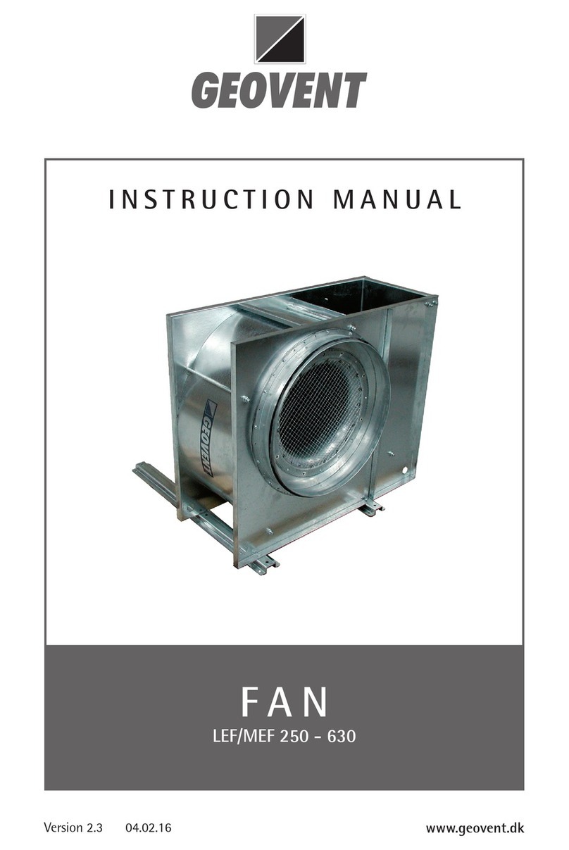
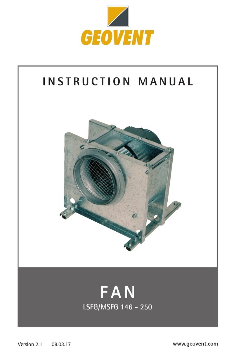
Geovent GEOFILTER GFX2 User manual

GEOFILTER GFX2
GFX2 3-1, GFX2 6-2, GFX2 9-3, GFX2 12-4
INSTRUCTION MANUAL
www.geovent.com
Version 1.0 10.02.21

2

3
Content
1.0 Instruction ...............................3
2.0 Safety ..................................3
2.1 General safety ...........................3
2.2 Danger ................................ 4
3.0 Machine oveview .........................4
3.1 Description ..............................4
3.2 Intended use ............................ 4
3.3 Machine specifications .....................5
3.3.1 Design ................................5
3.3.2 Technical Information ....................5
4.0 Transport ...............................6
5.0 Assembly, installation and start of operation ....6
5.1 Location ................................6
5.2 Installation ..............................7
5.3 Control and testing of the system .............7
6.0 Usage ..................................8
6.1 Use of the product .........................8
6.2 Parallel coupling of filters. . . . . . . . . . . . . . . . . . . 14
6.3 When the product has been installed .........14
7.0 Control, test and maintenance. . . . . . . . . . . . . . . 14
7.1 Control.................................14
7.2 Maintenance ............................14
7.3 Replacing the filter cartridges ...............16
8.0 Cleaning ...............................17
9.0 Troubleshooting..........................17
10.0 Dismantling, disabling and scrapping ........18
11.0 Multi coupling Diagram ...................19
12.0 Liability. . . . . . . . . . . . . . . . . . . . . . . . . . . . . . . . 22
13.0 Declaration of Conformity .................22
14.0 Appendix ..............................23
14.1 Spare parts list. . . . . . . . . . . . . . . . . . . . . . . . . . 23
1.0 Introduction
This manual is made and designed in order to facilitate
the best and most secure interaction with the product.
The manual is relevant for people involved in transpor-
tation, stocking, installation, using, maintaining and all
other thinkable interaction with the product.
The manual must be read in full and understood before
interacting with the product.
When the manual has been read and understood in full,
the table of contents can be used to find the relevant
information in each case.
The product is manufactured by:
Geovent A/S
Hovedgaden 86
DK-8861 Løgstrup
DENMARK
Tel.: (+45) 86 64 22 11
E-mail: [email protected]
www.geovent.com
This manual is to be used for all interactions with the
product including: Transportation, stocking, installation,
operation and maintenance.
This product is marked with: (example)
2.0 Safety
2.1 General safety
Carefully read this manual before use and observe the
safety instructions in order to avoid injuries!
Keep this manual in a safe place!
Secure that all users of the product have read this ma-
nual and that they follow the instructions as described.
Observe all instructions marked on the product!
Observe the indications of the manufacturer.
Never use the product if you are in doubt about how it
works or what you should do.
Observe all instructions marked on the product!
Observe the indications of the manufacturer.
When doing maintenance or replacing filter cartridges,
follow the instructions in chapter 7.0.
If the instruction manual has been lost, a new one must
be obtained without delay.
In case of illegible installation manual or illegible or un-
clear information and warnings on the product, these
must be replaced immediately with new ones.
If an alarm is weak or defective, it must be repaired or
replaced immediately. Never use the product with defec-
tive signalers.
Wires and pneumatic hoses must be replaced immedia-
tely if they are damaged. This replacement shall be car-
ried out by trained and qualified personnel.
Avoid making changes to the product and only use
spare parts from Geovent, otherwise, there is a risk of
destroying the product and its operation.
All electrical installations must be carried out by a autho-
rized electrician.

4
2.2 Danger
As the product is ATEX approved, it is designed to best
minimize the risk of explosion. To further minimize the
risk of explosion, the installation, servicing, and use of
the filter is required in accordance with this instruction
manual.
It is emphasized once again, that this manual is thorough-
ly read before installation and use.
It is a danger to life to open, separate, or otherwise
handle the product while it is in use.
Before servicing the product, a cleaning cycle must be
run and subsequently, the power must be turned off.
Generally, as a rule, the product should always be pla-
ced outdoors. If indoor placement is the only option, the
limb of the explosion membrane must be placed with a
way of connecting into the open air.
If the product is to be used for filtering wood dust, the
filter MUST be placed outdoors at least 2,5 m from the
nearest building. The explosion membrane must be po-
sitioned so that the hatch is opened away from the buil-
ding in the event of an explosion.
The explosion hatch must not be blocked on the outside
and placed in such a way that persons in the vicinity of
the product do not suffer any damage in the event of an
explosion.
When handling the product, gloves should be used to
protect the hands from damage.
Please note that the product may tip when it is moved.
The product must be handled carefully, and it must be
firmly fixed to a forklift, or other means of transport when
moving it.
Place the product on an even and stable base (e.g., a
concrete floor) and secure it. Make sure there is room for
maintenance and filter change.
The doors of the product must not be opened during
operation.
When replacing the filter cartridge, follow the instructi-
ons in Chapter 7.3.
Before starting maintenance work on the product, en-
sure that the pneumatics of the machine are discon-
nected and aerated, as well as supply separators for all
electrical equipment must be switched off (the voltage
disconnected). ”Switches which are switched off shall be
marked with a sign showing contact details and the text
must not be operated - work is carried out on the facility.”
In the event of a fire or accident:
- Call for help
- Disconnect the power connection
- Follow the normal procedures and local requirements
in the event of a fire or accident
In case of problems:
- Disconnect the power connection
- Inspect the product to conclude whether a repair is
possible
- If repair is not possible, the product must be scrapped.
Follow instructions for scrapping in Chapter 8.0.
3.0 Machine overview
3.1 Description
The GFX2 is a filter unit which is used for different filtra-
tion purposes.
The filter cartridge used must be carefully selected to
ensure effective filtering.
3.2 Intended use
The product is equipped so that it is ATEX approved.
In the event of an explosion in the filter, the explosion
hatch will ensure that the explosion pressure is dischar-
ged from the filter and into a secured area.
Thus, the product can be used to filter aluminium, flour,
and wood dust as well as other media associated with
explosion hazard (zones 20, 21, and 22 (D)).
The filter can of course also be used as a filter for other
processes, such as welding fumes that are not associa-
ted with the risk of explosion.
Mixing air from different processes is not recommended,
as this may increase the risk of explosion.
Clean Zone
Zone 22 (D)
Duct connection
Outlet
Duct connection
Inlet
Outside:
Non-ATEX
Dirty Zone
Zone 20 (D)

5
The product comes with filter cartridges of pleated texti-
les with ALU coating (filtration rate of 99.90% according
to DIN EN 60335-2-69:2008) The filter cleaning is auto-
matically done by sending a compressed air shock wave
through the filter cartridges, thereby blowing off the par-
ticles on the textile material. The particles land in the
collection bucket at the bottom.
3.3 Machine specifications
3.3.1 Design
Casing: Galvanized steel
(corrosion category III),
with baffle plate in the inlet.
Explosion membrane: Brilex KER, Atex approved,
in AISI 304
Filter cartridges: See filter table 1.3.
Air pressure tank: Powder coated steel
Automation: Filter control with digital display,
for shooting time, shot range,
and after-run cycle.
Collection bucket: Galvanized steel
– 25 liter capacity.
Explosion membrane: Brilex KER, Atex approved, in
AISI 304
1
SEQUENCER
SERIESE1T
USERMANUAL
04/02/2015
ManualRelease1.23
SoftwareRelease3.4
HardwareRelease1.2
TURBOS.R.L.
ElectronicControlSystemsforDustCollectors
e‐mail:info@turbocontrols.it
web:www.turbocontrols.it
TEL.++39(0)362574024
FAX++39(0)362574092
3.3.2 Technical data
Dimensions
Model/Dimension A
[mm]
B
[mm] Inlet
GFX2-3-1 775 335 ø250np
GFX2-6-2 810 635 ø315np
GFX2-9-3 855 935 ø400np
GFX2-12-4 900 935 ø500np
Model/Dimension Outlet
[mm]
Clearance
[mm]
Weight
[kg]
GFX2-3-1 ø250np min. 927 90
GFX2-6-2 ø315np min. 927 135
GFX2-9-3 2xø315np min. 927 180
GFX2-12-4 3xø315np min. 927 225
Duct connection
Inlet
Duct connection
Inlet
EX-membran
EX-membran
24V-50Hz
with grounding
connection
MTS4
24V-50Hz
with grounding
connection
MTS4
Copper
wire
Clean Zone
Zone 22 (D)
Hose 1”
Copper
wire
Copper
wire
Collection bucket
Collection bucket
Duct connection
Outlet
Duct connection
Outlet
Outside:
Non-ATEX
Outside:
Non-ATEX
Collection bucket
Dirty Zone
Zone 20 (D)
Filter cartridge
Filter cartridge
Galvanized steel
Compressed air tank
Timer control
Inlet with baffle plate
Filter cartridge Filter cartridge
Antistatic
Antistatic

6
Model Max. Airflow(*) Sound pressure
level
GFX2-3-1 1,800 m³/h 72 dB(A)
GFX2-6-2 3,600 m³/h 74 dB(A)
GFX2-9-3 5,400 m³/h 78 dB(A)
GFX2-12-4 7,200 m³/h 78 dB(A)
Compressed air: 3.5 - 6 bar - clean and dry air
Air consumption: 3 liters of compressed air
per shot
Power supply: 24VDC electricity. 230VAC
(standard)
Temperature: -12°C - +65°C
Corrosion Class: III
Sealing class.: Class C
Temperature exhausted air Max. 150°C
Temperature surroundings -10°C - +65°C
Relative humidity must be below <90%
Differential pressure drop
Typical pressure drop: 1000-1500 Pa
Filter
types Filtering Tested by
IFA Material
FT/11 99,9%
v/0.3my
DIN EN
60335-2-
69:2008
Polyester PTFe +
aluminium coated
Coa-
ting
Anti-
static Washable Filter
Area Use
ALU No No 10 m2Allround
The sound level depends on several factors. For exam-
ple, these circumstances affect the sound level: The
location of the product (indoor/outdoor), the size of the
room, the temperature of the surroundings, the reverb,
and the pressure loss in the filter.
Differential pressure over the product
Typical pressure loss: 1000-1500 Pa
The pressure loss over the filter varies depending on
how loaded and dirty the filter media are. When the pres-
sure loss exceeds 2000 Pa.
The filter cartridges should be changed.
The differential pressure in the filter must NOT
exceed 3,000 Pa.
4.0 Transport, handling and storage
During transport in a truck or in another means of trans-
portation the product must be securely packed in a box
or a pallet and covered with a water proff material.
The product must be securely stowed in the truck so that
it will neither tilt nor shift during transport.
During transport over a short distance e.g. in a stock or
a factory, the product can be moved by means of a forklift
or a stabeler.
When moved it must be secured that the product does
not tilt or shift. And it must be secured that the limitations
of the means of transportation is not exceeded.
Secure that there are no people around the product,
when the product is moved.
The product must be placed in a dry place and covered
securely, in order to secure that moist, metal parts or
other substances do not damage the product.
It is not allowed to place anything on top of the product.
5.0 Assembly, installation and start of
operation
5.1 Location
Generally, as a rule, the product should always be placed
outdoors. If indoor placement is the only option, the limb
of the explosion membrane must be placed with a way
of connecting into the open air.
If the product is to be used for ltering wood dust, the
lter MUST be placed outdoors at least 2,5 m from the
nearest building. The explosion membrane must be po-
sitioned so that the hatch is opened away from the build-
ing in the event of an explosion.
The explosion hatch must not be blocked on the outside
and placed in such a way that persons in the vicinity of
the product do not suer any damage in the event of an
explosion.
Place the product upon a solid, flat foundation (e.g. a
concrete floor) and anchor it.
Before installation, the optimal location must be found.
Is there room to perform satisfactory installation and ser-
vice of the product? Have the risks of an explosion been
taken into account? For example, in which direction the
explosion membrane opens. Are there optimal connecti-
vity options for piping and automation?
Outdoor installation must consider any noise disturban-
ces in neighbours and defects due to frost or rain. There-
fore, a shed should be built around the filter that shields
against noise, weather, and wind.
The explosion hatch must not be blocked on the outside
and placed in such a way that persons in the vicinity of
the product do not suffer any damage or damage in the
event of an explosion.
77
Therefore, place the filter 2.5m from the building, with
the explosion membrane pointing away from the buil-
ding. Also, ensure that random by-passers do not get hit
by the hatch
(opening of the explosion membrane).
In the case of an outdoor location, the explosion hatch
must point away from the building and in the direction
where there is at least the probability of a random passing
by. The filter should be placed 2.5m from the building.
5.2 Installation
The product is delivered complete and pre-programmed
from the factory, ready for connection of pipes and power.
Procedure:
1. Place the product over an even and stable base (e.g.,
a concrete floor) and secure it. Make sure there is
room for maintenance and filter change.
2. The product must be connected to a circular ventilati-
on pipe on both clean and dirty side.
(The bottom pipe connection is always the dirty side)
Remember to seal joints with sealant and/or tape!
3. Pipes must be sized so that they can withstand the
resulting pressure in the event of an explosion.
4. To ensure free mixing, the return should be carried
two meters above the roof ridge of the building to-
wards the atmosphere with a return rate of at least 8
m/s.
5. Connecting the electrical components of the product
must be carried out by an authorized electrician.
6. For connecting opportunities: Watch the following dra-
wings and instructions in Chapter 6.0. The electrical
installations on the machine must be carried out ac-
cording to DS/EN 60204-1 ”Electrical equipment on
machinery.
7. The packaging shall be sorted and disposed of accor-
ding to local rules and guidelines.
8. Equalization connections shall be fitted between all
interfaces and metallic parts to prevent uncontrollable
discharge of static electricity.
IMPORTANT:
Cleaning pressure is adjusted from 3.5 to 6 bar of
clean dry air as needed. If the cleaning pressure in-
creases to more than 6 bar there is a risk of dama-
ging the filter media.
In Denmark, all air extraction systems must be
equipped with a control device to check the correct
suction according to the Danish Working Environ-
ment Authority. Check more about Geovent Airbox
for this purpose.
5.3. Control and test of the security system
When the product is installed you must secure:
a. That the filter is placed on a solid, flat foundation and
anchored to the ground or the wall so that it cannot tilt.
b. That the doors of the product are securely closed.

88
6.0 Usage
6.1 Use of the product
The product comes standard with a timer control panel,
but in certain situations, it may be advantageous to let
the cleaning function control the pressure differential in
the filter. In this way, cleaning the filter will automatically
begin when the pressure loss over the filter reaches a
set point.
Be aware that the product is supplied with timer con-
trol or differential pressure control.
Menu
How to access programming
Press SET
Press + and - to select the required function.
Press OK to confirm.
Increase or decrease the value of the parameter
Press OK to confirm and exit.
Press SET again to exit programming mode.
Display
The display shows Off if terminals 14 and 15 are broken.
The display shows -0- if terminals 14 and 15 are closed
but 12 and 13 are broken (fan switch)
Cleaning function
The Cleaning function is programmable.The shock wave
and timer control can be set in the function menu.
The shock wave should be adjusted for the current ap-
plication. From factory, it is set to shoot every 350 se-
conds. The timer setting may be changed in F3.
Cleaning function with off fan
The function allows one or more cleaning sequences
(the number selected in F13), when the fan is turned off.
The cleaning time is always as selected in F02, while the
pause time is selected in F14.
The display alternately shows the number of seconds to
cleaning and the code ”PCC”.
List of Functions
F02: Activation time.
Possible values: 0.5 - 5.00. Step 0.01
Default = 0.20
F03: Pause time, cetween shots:
Possible values: 001 - 999. Step 1
Default = 175
F04: Number of valves.
Possible values: 01 - 16
Default = Automatic
F05: Output voltage.
Possible values: d24 / a24 /115 / 230.
Default = a24
F06: Manual cleaning cycle.
Possible values: The number of valves set in F4
Press SET to activate.
F13: Cleaning cycles after fan stop.
Possible values: 01 - 99. Step 1
Default = 01
F14: Pause time between cleaning cycles after fan
stop.
Possible values: 001 - 999. Step 1
Default = 20
F15: Service timer.
Possible values: 001 - 999. Step 1 (1=10 h)
Default = 100 (1000 h)
F16: Service alarms.
Possible values: 0 (off) -1 (on).
Default = 0 (off)
F17: Reset service timer.
Possible values: 0 (off) -1 (reset).
Default = 0 (off)
Note: The service timer will be reset and the F17 will be
reset to 0 by setting F17 to 1.

9
Sikring
Alarms:
The unit runs a number af checks during the start-up cycle and during normal operation.
The possible alarms and respective solutions are shown in the following table.
Alarm Description Action
E01 F05 set to 24Vdc - ac jumper detected.
24Vdc, switch the device off and move the ac/dc jumpers to dc.
24Vac, Press OK, then press SET, set the function F05 using
+/-, select A24 and press OK to confirm.
E02 F05 set to 24Vac - dc jumper detected.
24Vac, switch the device off and move the ac/dc jumpers to ac.
24Vdc, Press OK, then press SET, set the function F05 using
+/-, select d24 and press OK to confirm.
E03 F05 set to 24Vac or 24dc.
Voltage out of range detected.
24V valves, switch the device off and move the output voltage
selection jumper to 24V. If the jumper is in the correct posi-
tion, press OK then SET, select the F05 function with +/- set
the correct current and press OK.
E04 F05 set to 115V or dc.
Voltage out of range detected.
115V valves, switch the device off and move the output volta-
ge selection jumper to 115V. If the jumper is in the correct
position, press OK then SET, select the F05 function with +/-
set the correct current and press OK.
E05 F05 set to 230 V.
Voltage out of range detected.
230V valves, switch the device off and move the output volta-
ge selection jumper to 230V. If the jumper is in the correct
position, press OK then SET, select the F05 function with +/-
set the correct current and press OK.
E06
The current of the solenoid valve is lower
than the minimum threshold or discon-
nected solenoid valve.
Check that the solenoid valve is connected correctly and the
respective data.
The alarm is self-reset.
E07 The current of the solenoid valve is hig-
her than the maximum threshold.
Check that the solenoid valve is connected correctly and the
respective data. The alarm is self-reset.
E08 Output short circuit.
Alarm cannot be reset
Switch the filter off, check the solenoid valve, and switch the
filter back on.
E11 Maintenance deadline reached. Carry out maintenance.
Power supply
Fuse
Alarm relay
Fan contact
-P1 dp lter dirty site
-P2 dp lter clean site
Switching on the cleaning cycle
Note: Lus can be used digital input

1010
Connections diagram
9
Connectiondiagram
Power Supply
Alarm relay contact
Fan contact inout
Enable contact input
Solenoid valve output
Supply voltage: 230V AC
Alarm relay: No (Max 3A@250V AC)
Fan input: Open = Fan off
Closed = Fan on
Enable Cleaning: Open = Cleaning disabled
Closed = Cleaning enabled
9
Connectiondiagram
Power Supply
Alarm relay contact
Fan contact inout
Enable contact input
Solenoid valve output
Supply voltage: 230V AC
Alarm relay: No (Max 3A@250V AC)
Fan input: Open = Fan off
Closed = Fan on
Enable Cleaning: Open = Cleaning disabled
Closed = Cleaning enabled

11
2.1.3 Dierential pressure control (OPTION)
• In automatic mode (F01=1)
dp value alternating with OFF if the enabling switch
(14-15) is off.
dp value alternating with -0- if the enabling switch (14-
15) is on but 12 and 13 are off.
dp valve only if the fan is on and active.
• I manual mode (F01=0)
OFF if the enabling switch is off (14-15)
-0- if the enabling switch (14-15) is on and the fan is off
Manual operating mode F01=0
The economiser will work as a programmable cycle se-
quencer in manual mode. The connected outputs will
be activated at the programmable frequencies. Manual
mode can be activated by accessing the configuration
menu and setting F01 to 0. F02 and F03 will set the acti-
vation time and the pause time, respectively.
Automatic operating mode F01=1 (Standard)
By selecting automatic mode (F01=1), the economie-
ser will work autonomoulsy and carry out the pneumatic
washing cycle only when needed. The device will start
the washing cycle if the obstruction is higher than Thres-
hold_DP_Start (F08). Washing is suspended when
obstruction drops under Threshold_DP_Stop (F09) level
until it reaches a value higher than the Threshold_DP_
Start threshold once again. When washing is active, the
economiser respects the times set in F02 (operating
time) and F03 (pause time).
Automatic mode with forced cycle F01=2
Identical to the automatic mode, except for the fact that it
is possible to obtain a cleaning cycle with the activation
of the solenoid valves connected without reaching the
Threshold_DP_Start (F08). The forced cleaning interval
may range from 1 to 999 h and can be selected through
function F22.
Proportional mode F01=3
With the proportional mode, the economiser will work
in full autonomy, initially setting the DP_Start threshold
(F08), activation time (F02) and pause time (F03). When
the Start Cleaning threshold is exceeded, the solenoid
valves are automatically activated in sequence. If the dp
threshold drops below 15% at the end of an entire cycle
of pulses of the connected solenoid valves, the washing
is suspended until pressure returns to a value above the
Start Cleaning dp value. If the dp value does not drop be-
low 15% of the Start Cleaning threshold, the frequency of
the time is automatically reduced in proportion with each
entire cycle of pulses of the connected solenoid valves,
until a minimum cycle time between solenoid valves rea-
ches 10 seconds. The minimum threshold of 10 seconds
has been chosen in order not to hamper the dispensing
of air by the compressor connected to the filter.
Cleaning function with fan off (PCC)
This function allows to carry out one or more cleaning
cycles (the number of cycles is defined by F13) when the
fan is off.The on or off state of the fan may be determi-
ned by the state of contacts 12-13 (contacts open = fan
off). If F11=0, or may be determined automatically (with
F11=1) when the dp pressure drops under the threshold
defined in F12.The pulse time of the valves will always
be that defined in F02, while the pause time in this case
is defined in F14.
The display alternatively showes the number of the val-
ve activated and the word ”PCC”.
Number of output selection
The number of outputs (solenoid valves), on which the
sequencer will run the cleaning cycle, can be selected.
Cleaning will be carried out in order from the first to last
solenoid valve. The valves can be adjusted by the F04
function.
dp 0 calibration (F07)
This function is used to reset dp reading with the fan off.
Increase or decrease the value shown by pressing + and -
as required. This value will be subtracted from the value
read by the dp sensor.
dp sensor self-calibration
This function allows to reset dp reading with the fan off
automatically.
Hold SET and OK at the same time with the device off.
The message CAL will appear after the start-up test.
Release the buttons. The unit will go back to normal
state after a few instants.
Automatic calibration is complete.
Fuse
Fuses can be replaced with selected Amp consumption:
3A = 24Vdc / ac

12
F14: Pause time betwen cleaning cycles
after fan stop.
Possible values: 001 - 999. Step 1
Default = 10
F15: Service timer.
Possible values: 001 - 999. Step 1. (1=10 h)
Default = 100 (1000 h)
F16: Service alarm.
Possible values: 0 (disabled) -1 (enabled).
Default = 0 (disabled)
F17: Reset service timer.
Possible values: 0 (disabled) -1 (reset).
Default= 0 (disabled).
Note: The service timer will be reset and the
F17 will be reset to 0 by setting F17 to 1.
F18: Precoating function enabling.
Possible values: 0 = (disabled) 1 = (enabled)
Default = 0 = (disabled)
F19: dp threshold for precoating function.
Possible values: 0.00 kPa - 3.99 kPa. Step 0.01
Default = 2.00 kPa
F20: Enabling Minimum DP Alarm function.
Possible values: 0 (disabled) 1 = (enabled)
Default = 0 (disabled)
F21: Min. DP Alarm Threshold
(Broken Sleeve/Cartridge).
Possible values: 0.00 kPa - 3.99 kPa. Step 0.01
Default = 0.20 kPa
F22: Forced Cleaning Cycle
(Available only in funktion mode F01 = 2).
Possible values: 1 h - 999 h. Step (1 h)
Default = 4 h
List of Functions
F01: Activation time.
Possible values:
0 - Manual (∆p excluded)
1 - Automatic (Default)(∆p included)
2 - Automatic with forced cycle (∆p included)
3 - Proportional (∆p included)
F02: Activation time.
Possible values: 0.05 - 5.00. Step 0.01
Default = 0.20
F03: Pause time.
Possible values: 001 - 999. Step 1
Default = 020
F04: Number of valves.
Possible values: 01 - 16. Step 1
Default = Dependant on filter size
F05: Output voltage.
Possible values: d24 / a24 /115 / 230
Default = a24
F06: Manual cleaning cycles.
Possible values: 1 the number of valves speci-
fied in F04.
F07: Zero dp threshold.
Possible values: 0.00 kPa -3.99 kPa. Step 0.01
Default = 0.00 kPa
F08: Cleaning cycle start threshold.
Possible values: 0.00 kPa - 3.99 kPa. Step 0.01
Default = 0.80 kPa
F09: Cleaning cycle stop threshold.
Possible values: 0.00 kPa - 3.99 kPa. Step 0.01
Default = 0.40 kPa
F10: Max DP Alarm Threshold. (Filter Clogging)
Possible values: 0.00 kPa - 3.99 kPa. Step 0.01
Default = 3.00 kPa
F11: Fan on recognition mode.
Possible value: 0 = fan input
Possible value: 1 = pressure
Default = 0
F12: dp threshold for fan on recognition if F11=1.
Possible values: 0.00 kPa - 3.99 kPa. Step 0.01
Default = 0.10 kPa
F13: Cleaning cycles after fan stop.
Possible values: 01 - 99. Step 1
Default = 01

1313
Alarms
The unit runs a number af checks during the start-up cycle and during normal operation.
The possible alarms and respective solutions are shown in the following table.
Alarm Description Action
E01 F05 set to 24Vdc -
ac jumper detected
24Vdc, switch the device off and move the ac/dc jumpers
to dc.
24Vac, Press OK, then press SET, set the function F05
using +/-, select A24 and press OK to confirm.
E02 F05 set to 24Vac -
dc jumper detected
24Vac, switch the device off and move the ac/dc jumpers
to ac.
24Vdc, Press OK, then press SET, set the function F05
using +/-, select d24 and press OK to confirm.
E03 F05 set to 24Vac or dc.
Voltage out of range detected.
24V valves, Switch the device off and move the
output voltage selection jumper to 24V.
If the jumper is in the correct position, press OK then
SET, select the F05 function with +/- set the correct current
and press OK
E04 F05 set to 115V eller dc.
Voltage out of range detected.
115V valves, switch the device off and move the
output voltage selection jumper to 115V.
If the jumper is in the correct position, press OK then
SET, select the F05 function with +/- set correct current
and press OK
E05 F05 set to 230 V.
Voltage out of range detected.
230V valves, switch the device off and move the output
voltage selection jumper to 230V.
If the jumper is in the correct position, press OK then
SET, select the F05 function with +/- set correct current
and press OK
E06
Solenoid valve current lower
than minimum threshold or
disconnected solenoid valve.
Check correct connection of the solenoid valve and
respective data.
The alarm is self-reset.
E07 Solenoid valve current higher
than maximum threshold.
Check correct connection of the solenoid valve and
respective data.
The alarm is self-reset.
E08 Output short circuit.
Alarm cannot be reset
Switch the device on and back on after having checked the
solenoid valve system.
E09 dp maximum pressure
exceeded (F10) Check state of filtering elements.
E10 dp sensor hardware offset
out of range
The self-calibration of the dp sensor has determined that a
value is out of range. Disconnect the air tubes and repeat
the function. Take the device to be serviced if the alarm
occurs again.
E11 Maintenance deadline reached Carry out maintenance
E12 dp sensor full-scale value reached
Check state of filtering elements.
Important: Running in this condition may damage the
device.
E13
Minimum DP alarm value
ranging from F12 to F21
(Warning: The alarm is generated with a
fixed delay af 60 seconds)
Check the status of the filtering elements.

14
7.0 Control, test and maintenance
7.1 Control
Before usage, check that the cleansing intervals are
adjusted to the purpose.
Make sure that the pause intervals are adjusted to the
load and adjust if necessary. (See Chapter 6.0)
Check for vibration or noise issues during use of the pro-
duct. Check that the entire system is completely sealed.
In case of squeaking sounds, locate leakage and seal
with joint ller.
We recommend checking the ventilation system to en-
sure, that it is delivering the amount of air which the
system is proportioned for. Measure the amount of air
and regulate using the regulation valve. In the event of
overcapacity, the power usage can exceed the capacity
of the fan motor, thereby causing the motor to burn out.
See the manual of the fan.
7.2 Maintenance
If an alarm is weak or defective, it must be repaired or
replaced immediately. Never use the product with defec-
tive signalers.
The entire point extraction system should be looked
after at least once a year by a qualified service engineer.
Periodic maintenance:
• Annually, all electrical parts should be checked.
• Make sure that the compressed air supply is clean and
dry so that filter cartridges and shot valves are not da-
maged by condensation.
• Check the pressure loss over the filter and replace filter
cartridges if this exceeds 2000 Pa.
• Check the filter clean side for dust particles at regular
intervals and replace filter cartridges in case of leaks.
Before starting maintenance work on the product, ensure
that the pneumatics of the machine are disconnected
and aerated, as well as supply separators for all electrical
equipment must be switched off (the voltage disconnec-
ted). Switches which are switched off shall be
marked with a sign showing contact details and the text
”Must not be operated - work is carried out on the facility.”
Emptying of collection bucket
Emptying the collection bucket should be done when it
is about 2/3 full, otherwise, it may further strain the filter
cartridge. The contents of the bucket must then be pro-
perly destroyed in accordance with the applicable rules.
”When servicing the product, such as emptying
the collection bucket and replacing files, brea-
thing protection, protective gloves and goggles,
antistatic clothing and waste sets MUST be used.”
6.2 Parallel coupling of filters
For air volumes greater than what one module can hand-
le, the GFX2 filters must be connected in parallel.
6.3 When the product has been installed
When assembly of the filter is complete, installed correctly
and ready for use, there will not be any interaction bet-
ween the user and the filter besides emptying the bucket.
Naturally, the user should be aware of whether there is
correct suction in the exhaust system. See chapter 7.3.
When filtering processes where the filter media is
exposed to heavy load, it may be necessary to use
prekote. Prekote is a granule that is added to the
filter and increases the life of the filter media.
See separate instructions on this or contact Geovent
for more information.
IMPORTANT: It is imperative that the cleaning
cycle intervals are adjusted according to the load put
on the filter.
First when installing and secondly after a period
where it is evaluated if the intervals between clea-
ning shots should be shorter or longer.
If the shots are fired too often, the energy cost will
be higher.
Are the shots fired too seldom there will be more
strain on the fan making fitration more costly and
ineffective and it will shorten the lifespan of the filter
cartridges.
GFB filter
modul 1
GFB filter
modul 2
Centralventilator
AFKAST
Side med ren
luft I rør
Side med beskidt
luft I rør GFX2 filter
module 1
Dirty air Dry and clean air
Central fan
Outlet
GFX2 filter
module 2

15
Open and close the door
1. Pull the handle up.
2. Pull/roll out the bucket and empty
3. Roll bucket in and push handle down while holding
bucket in place.
1. Loosen the bolts, turn the latch 90° to the left.

16
3. Unscrew all screws that hold the filter lid with a top
wrench.
2.The door opens (the filter cartridge can be replaced).
3. Close the door again, while holding it in place.
4. Turn the latch 90° to the right, while holding the door
in place.
5. Tighten the bolts until the latch is tightly secured to
the doors.
Security check:
1. Check that all 4 locks are tightened so they cannot be
loosened by hand.
2. Pull the handle slightly to make sure it is closed tightly.
After any repair, maintenance, etc., compensatory con-
nections for the discharge of static electricity must be
refitted correctly.
7.3 Replacing the filter cartridges
The filter cartridge should be replaced after approxima-
tely 4000-8000 hours of operation or max. 4 years. This
depends partly on the load on the filter and partly what
it is used for.
Approach:
1. Before removing the filter door, it is important that the
service technician wears the necessary personal sa-
fety measures, such as breathing protection, protec-
tive gloves and goggles, and antistatic clothing that
complies with the Working Environment Authority’s
rules for working with contaminated dust.
2. All power must be disconnected, and it should be en-
sured that the power cannot be activated during service.
4. Turn the filter to remove it.
5. Place the contaminated filter in a plastic bag and dis-
pose it according to rules for hazardous waste.
6. Mount the clean filter cartridge by repeating the above
steps in reverse order.
7. Check the filter for functionality and leakage before
use.
How do you optimize your filter?
1. Choose the correct filter cartridges for the job
2. Clean using correct air pressure
3. Correct injection sequence setting
4. Daily addition of Prekote
5. Ensure that the filter cartridges is dry
6. Shut down cleaning
After any repair, maintenance, etc., compensatory con-
nections for the discharge of static electricity must be
refitted correctly.

17
8.0 Cleaning
The outside of the product is cleaned by means of a
vacuum cleaner or a damp cloth.
NOTE: Do not clean the product during operation. Turn
the product off before cleaning.
The filter self-cleans automatically as a compressed air
pulse is sent down through the filter cartridges, causing
the particles on the textile of the filter to be blown off and
collected in the bucket below.
NOTE: Do not open the doors during operation to avoid
injury.
Cleaning of the inside of the product is not recommended.
When the doors of the product are opened, you must
wear protection gloves, eye protection and a suit cove-
ring your body.
9.0 Troubleshooting
In the event of problems caused by increased pressure
loss, low amounts of air etc., go through the following
points:
When overloading the parts of the product, the operator
must inspect the entire product for defects before re-
starting.
Dust proceeds to come out of the inlets
The cleaning system is having to “blow” too much dust
off the cartridges at one time and the dust is seeping into
the tubes. Reduce the pause interval on the filter control
until the dust no longer comes out through the inlets.
Pressure loss increases quickly during use and air
level falls accordingly
The cleaning system cannot keep up with the dust level.
- Reduce the pause interval until the pressure loss is
normal again. If this fails, the lter cartridge must be
changed.
- Increase cleaning pressure (to a maximum of 6 bar, as
the lter cartridges could otherwise be damaged).
- Increase after-cleaning.
Dirty lter alarm
Either the filter cartridge is torn or needs to be replaced
immediately (pressure differential is too low) or the filter
cartridges are nearing the end of their lifecycle, and
need to be replaced (pressure differential too high).
After any repair, maintenance, etc., compensatory con-
nections for the discharge of static electricity must be
refitted correctly.
Application
15-335
15-480 FL
15-108
Dustbox
15-482
03-260
HVU
03-259
HVU
03-260
HVU-it
15-480A
15-481 FL
Oil mist X X
Dry welding smoke X
Oil saturated welding smoke P*
Foundry X
Zink X X X
Powder coating X X
Plasma / lazer cutting P*
Sandblasting / Sand X
Sandblasting / Glass M*
Sandblasting / enamel, steel, aluminium X X X
Grinding X X X X X
Unspecied dust - no smoke X
Milk powder X
Spice A*
Tobacco X
Paper X
Chalk X
Cement X
Saw dust A*
*Notes: P = Prekote M = Moisture resistant A = ATEX approved
Filter media and their use (Indicative)

18
10.0 Dismantling, disabling and scrapping
Deactive the product by disconnection the electrical
mains. Dismantle the compressed air pipes and other
tubes etc.
When you dispose of the product you should dismantle
the filter elements as described in chapter 7.3.
It is very important that the instructions of this ma-
nual is followed in order to avoid contamination of
people and the environment!
The inside of the product must be cleaned by means of
a vacuum cleaner with a filter which suits the purpose.
Dismantle the electronics, wires and cables and put
these into a suitable bag. Afterwards dispose of it accor-
ding to local regulations.
Dismantle the metallic parts by unscrewing screws and
bolts. Afterwards cut the larger pieces into smaller pie-
ces and dispose of it according to local regulation.
BEWARE of sharp edges of the metallic parts which
could harm persons etc.
The packing material must be sorted according to local
regulation in order to be able to reuse the material.

19
11.0 Multi coupling Diagram
When T4 (oating input) is
activated the Multibox is
activated and CTS and
relay motor in the bottom
is activated.
+24V
CTS relay -
activated when
the box is
activated.
T2 - 24V out
230V
10 11
Machine/welder
Note: If error, switch terminal 2 and 3 on freqency converter. This will typically solve the problam as 0V is sent in to AI
Control on GFB2 Filter
12 13 15 16
JN0
230 V
Multibox III
JN08910
230 V
MOTORAlarm
Terminals
123
GFD Damper
123
54
Sensing coil
Machine/welder
NF
380 V
NF JFF
Power Smart
START/STOP SIGNAL FOR FAN/MULTIBOX - connected in parallel
U + V + W +PE
1
2
3
4
5
6
7
8
9DI2
Start/Stop signal
PowerBox III
230 V
GND+24V+24V
GFD Damper
123
NO
CNC
Power coil connects to
10 and 11
One phase from the
welding plant is looped
through the sensing coil
MULTI COUPLING DIAGRAM - TERMINALS, MULTIBOX AND FREQUENCY INVERTERS
T10 is only used
in Multibox
SRC
AI1
AGND
GND
DCOM
DI1
400 V
L1
L1
L1
PE
Fi
R-
R+
ABB ACH 580
Start/Stop signal
U + V + W +PE
1
2
3
9
10
11
12
13
24V
T10 is only used
in Multibox
SRC
AI
GND
GND
COM
DI1
400 V
L1
L1
L1
PE
Fi
R-
R+
ABB ACS 150
Start/Stop signal
Connect one of the
following frequency
inverters
NL
CTS
Quick guide - also see manual
P0: Version selector - select 530 (most common)
P1: Adjustment set point [Pa]
P2: Min. Alarm limits [s] at too low pressure
P3: Max. Alarm limit [s] at too high pressure
P10: shows current pressure.
Adjusting the frequency inverter:
See manual - important parameters to adjust:
Motor data: Typically parameter group 99
Ramp up/down: Typically parameter group 22.
Frequency Max/Min:
Typically parameter group 20 and 11
IMPORTANT
Jumper on the bottom (S1) must be
switched from “I” to “U”
This will change output from current to voltage.
Remember to bridge GND and COM.
Enable input
Fan input
Adjusting Multibox III:

20
Dimensions
GFX2-3-1
Dimensions
GFX2-6-2
This manual suits for next models
4
Table of contents
Other Geovent Fan manuals

Geovent
Geovent MEF Series User manual

Geovent
Geovent W3 Filter Unit User manual

Geovent
Geovent LSFG 146 User manual

Geovent
Geovent MSQ 200 User manual

Geovent
Geovent PM-225 User manual

Geovent
Geovent LSFG-146 User manual

Geovent
Geovent MVF-125 User manual

Geovent
Geovent MSX-146 User manual

Geovent
Geovent GEOFILTER Oil 100 User manual

Geovent
Geovent PM-180-1 User manual
Popular Fan manuals by other brands

Euroclima
Euroclima ZHK Series instruction manual

ARDES
ARDES AR5D40P Instructions for use

Kendal Lighting
Kendal Lighting AC-23856 installation instructions

Broan
Broan 510 installation instructions

Qazqa
Qazqa Cool Fan 52 instruction manual

Venture Industries
Venture Industries IBF Series Operation and assembly manual