8
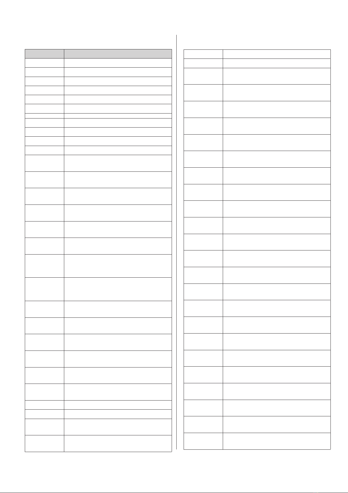
14.0 Spare part list
Art. No. Description
10-520 Table spring for 1490 mm PERMA arm
10-521 Wall spring for 1490 mm PERMA arm
10-525 Tight damper - ø57 mm
10-526 Tight damper - ø76 mm
10-527 Tight damper, ESD - ø57 mm
10-528 Tight damper, ESD - ø76 mm
10-316 Hood ø380 mm, polycarbonatee, ø57
10-416 Hood ø380 mm, polycarbonatee, ø76
10-316A Hood ø280 mm, polycarbonatee, ø57
10-416A Hood ø280 mm, polycarbonatee, ø76
10-317 Hood conical ø250 mm, polycarbonate,
ø57
10-417 Hood conical ø250 mm, polycarbonate,
ø76
10-318 Hood conical ø250 mm, polycarbonate,
m. flexrør 300 mm, ø57
10-418 Hood conical ø250 mm, polycarbonate,
m. flexrør 300 mm, ø76
10-319 Hood conical ø250 mm, polycarbonate,
straight edge, ø57
10-419 Hood conical ø250 mm, polycarbonate,
straight edge, ø76
10-320 Hood conical ø250 mm, polycarbonate,
m. flexrør 300 mm straight edge, ø57
10-420 Hood conical ø250 mm, polycarbonate,
m. flexrør 300 mm straight edge, ø76
10-321 ALU Hood conical ø150 mm, ø57
10-421 ALU Hood conical ø150 mm, ø76
10-366 ALU Hood conical ø150 mm, ESD, ø57
10-466 ALU Hood conical ø150 mm, ESD, ø76
10-323 Hood 340x250 mm, polycarbonate, ø57
10-425 Hood 340x250 mm, polycarbonate, ø76
10-324 Suction Pen L:250 mm, ALU, ø57
10-422 Suction Pen L:250 mm, ALU, ø76
10-367 Suction Pen L:250 mm, ALU, ESD, ø57
10-467 Suction Pen L:250 mm, ALU, ESD, ø76
10-325 Suction Pen L:350 mm, ALU, ø57
10-423 Suction Pen L:350 mm, ALU, ø76
10-368 Suction Pen L:350 mm, ALU, ESD ø57
10-468 Suction Pen L:350 mm, ALU, ESD, ø76
10-324A Suction press flange L:250 mm, ALU,
ø57
10-422A Suction press flange L:250 mm, ALU,
ø76
10-367A Suction press flange L:250 mm, ALU,
ESD, ø57
10-467A Suction press flange L:250 mm, ALU,
ESD, ø76
10-325A Suction press flange L:350 mm, ALU,
ø57
10-423A Suction press flange L:350 mm, ALU,
ø76
10-368A Suction press flange L:350 mm, ALU,
ESD, ø57
10-468A Suction press flange L:350 mm, ALU,
ESD, ø76
10-326 Suction Pen L:150 mm w/ flextube 300
mm, ALU, ø57
10-424 Suction Pen L:150 mm w/ flextube 300
mm, ALU, ø76
10-369 Suction Pen L:150 mm w/ flextube 300
mm, ALU, ESD, ø57
10-469 Suction Pen L:150 mm w/ flextube 300
mm, ALU, ESD, ø76
10-326A Suction press flangeL:150 mm w/
flextube 300 mm, ALU, ø57
10-424A Suction press flange L:150 mm w/
flextube 300 mm, ALU, ø76
10-369A Suction press flange L:150 mm w/
flextube 300 mm, ALU, ESD, ø57
10-469A Suction press flange L:150 mm w/
flextube 300 mm, ALU, ESD, ø76
10-370 Suction Pen L:150 mm w/ flextube 600
mm, med spjæld, ALU, ø57
10-371 Suction Pen L:150 mm w/ flextube 900
mm, med spjæld, ALU, ø57
10-329 Sugetragt oval 140x180 mm, polycar-
bonate, ø57
10-382 Sugetragt oval 140x180 mm, painted
polycarbonate, ESD, ø57
10-374 Hood, ø380 mm, painted polycarbona-
te, ESD, ø57
14.0 Spare part list