GeoVision GV-IP User manual

Quick Start Guide
GV-IP Decoder Box and GV-Pad
© 2011 GeoVision Inc. All rights reserved.
Thank you for purchasing GV-IP Decoder Box and GV-Pad. This guide is designed to assist the
new user in getting immediate results from the GV-IP Decoder Box and GV-Pad. For advanced
information on how to use the GV-IP Decoder Box and GV-Pad, please refer to GV-IP Decoder
Box and GV-Pad User's Manual on Software DVD.
Note: no SD/SDHC card slot or local storage function in Argentina
1Introduction
Welcome to the GV-IP Decoder Box / GV-Pad Quick Start Guide. In the
following sections, you will learn about the basic configuration and features
of the GV-IP Decoder Box / GV-Pad. For a detailed user’s manual, see
GV-IP Decoder Box and GV-Pad User’s Manual on software DVD.
●GV-IP Decoder Box × 1
●AC/DC adapter × 1 (12 V, 3 A, 36 W)
●Software DVD x 1
2011/11
English
DBV10-QG-A
GV-IP Decoder Box
●GV-Pad × 1
●Magnetic hinge x 1
●AC/DC adapter × 1 (12 V, 3 A, 36 W)
●Software DVD x 1
●IR remote control × 1
●Power cord x 1
●IR remote control × 1
●Screw x 4
●Power cord x 1
GV-Pad
Packing List
Analog camera GV-IP Camera Some 3
rd
party
IP cameras
through RTSP
GV-PT/PTZ
GV-IP Decoder Box GV-Pad
or
or
GV-Video Server
GV-Compact DVR
LAN
GV-IP devices,
analog cameras
and some
third-party
cameras
Computer installed
with GV-System and
GV-Mobile Server

The GV-IP Decoder Box / GV-Pad is compatible with most GeoVision IP
devices (of the indicated firmware versions) and several third-party IP
devices that support RTSP. The supported devices are listed below.
To decode and display non-H.264 IP channels or analog channels, connect
the devices to GV-System and access them through GV-Mobile Server. The
supported devices are listed below.
Supported Devices Connected to GV-System
Analog cameras
All models of GeoVision IP cameras, GV-Video Server, GV-Compact DVR,
GV-IP Speed Dome, GV-Smart Box and GV-DSP LPR
11 brands of third-party IP cameras. For detail, see
http://www.geovision.com.tw/english/4_21.asp
Supported GeoVision IP Devices
Device Type
Box Camera
Bullet Camera
Cube Camera
Fixed Dome
Vandal Proof IP Dome
Mini Fixed Dome
PT Camera
PTZ Camera
Speed Dome
Video Server
Compact DVR
IMPORTANT: The connected GeoVision and third-party channels must be set with
H.264 codec to be compatible.
Compatible Devices
Optional accessories can expand the capabilities and versatility of your
GV-IP Decoder Box / GV-Pad. Contact your dealer for more information.
Description
For GV-IP Decoder Box only.
Used to mount GV-IP Decoder Box
on wall.
For GV-IP Decoder Box only.
Used to mount GV-IP Decoder Box
on the back of a VESA monitor.
Connected to GV-IP Decoder Box /
GV-Pad to control GV PTZ cameras
including GV-PT110D, GV-PTZ010D
and GV-IP Speed Dome.
Device
Wall Mount Kit
VESA monitor
mount kit
GV-Joystick
Options
Models
GV-BX110D
All models
(except GV-BX110D)
GV-BL110D
All models
(except GV-BL110D)
All models
GV-MFD110
All models
(except GV-MFD110)
GV-PT110D
GV-PTZ010D
All models
GV-VS04H
GV-VS11
GV-VS12
GV-Compact DVR
V3 series only
Firmware Versions
V1.08 or later
V1.06 or later
V1.08 or later
V1.06 or later
V1.06 or later
V1.08 or later
V1.06 or later
V1.08 or later
V1.08 or later
V1.02 or later
V1.04 or later
V1.0 or later
V1.05 or later
V1.0 or later
Supported
Third-Party IP
Devices
Axis P1311
Sanyo
VCC-HD2100P
Sanyo
VCC-HD5600P
Vivotek IP8151
Pelco D5118
Samsung
SNB-3000N

2Overview
Front View
GV-IP Decoder Box
1 2 3 4 5
Name
LED Indicators
USB
IR
Default
SD Card Slot
No.
1
2
3
4
5
Function
The green LED indicates the system is ready for
use.
The red LED indicates the power is supplied.
Connect to a GV-Joystick, or to a USB storage
device for local storage of snapshot and
firmware upgrade.
Built-in IR receiver to receive the IR signals from
the IR remote control.
Reset the GV-IP Decoder Box to the default
factory settings. Use a pin to press the button
until the green LED fades. This will take about
10 seconds. The system will then reset and
reboot itself shortly.
Connect to an SD card for local storage of
snapshot and firmware upgrade.
Back View
1 2 3 4 5
Name
Network
HD
VGA
Power OFF/ON
DC 12V
No.
1
2
3
4
5
Function
Connect to the network.
Connect to an HD-supported display device.
Connect to a VGA monitor.
Switch the power on or off.
Connect to power by using the supplied power
adapter.
Note: The SPDIF and L/R ports are not functional.

Name
SD Card Slot
USB
LED Indicators
IR
Network
No.
1
2
3
4
5
Function
Connect to an SD card for local storage of
snapshot and firmware upgrade.
Connect to a GV-Joystick, or to a USB storage
device for local storage of snapshot and
firmware upgrade.
The green LED indicates the system is ready
for use.
The red LED indicates the power is supplied.
Built-in IR receiver to receive the IR signals from
the IR remote control.
Connect to the network.
Right Panel View
GV-Pad
1
2
3
5
4
Name
MENU
ENTER
UP
DOWN
LEFT
RIGHT
STAND BY
Power OFF/ON
DC 12V
No.
1
2
3
4
5
6
7
8
9
Function
●Switch to the setup menu.
●Load default: Press for 10 seconds to load default
settings.
●Save settings in the Setup Menu.
●Display selected channels.
Move the cursor up.
Move the cursor down.
●Move the cursor left.
●Unselect a channel on the Device List.
●Move the cursor right.
●Select a channel on the Device List.
Press to enter the Standby mode. In the standby mode,
the screen turns off to minimize power consumption.
Press the key again to enter the ON mode.
Switch the power on or off.
Connect to power using the supplied power adapter.
Left Panel View
1
2
3
5
6
7
8
9
4

The IR Remote Control
10
Name
Power
Numeric /
Alphabetical /
Punctuation
Marks keys
Back
Arrow
REC
Loop Start /
Stop
No.
1
2
3
4
5
6
Function
Turn on or off the GV-IP Decoder Box / GV-Pad.
Enter numbers, alphabets or punctuation marks.
Back to the previous page in the Setup Menu.
●Move up, down, right and left in the Setup Menu.
●Right arrow key: select a channel on the Device List.
●Left arrow key: unselect a channel on the Device List.
Capture a snapshot.
●Start or stop sequential display.
●Display and fix at a channel: press the Loop Start /
Stop key, a numeric key and OK to display and fix at
the selected channel. Press 0and OK to return to the
last displayed channel.
Name
Menu
OK
Shift
INFO
No.
7
8
9
10
Function
Switch to the setup menu.
●Save settings in the Setup Menu.
●Display selected channels.
Switch among the 8 resolutions. When the key
is pressed, the Green LED on the front panel
flashes. Press No. 0 ~ 7 for the desired
resolution within 30 seconds.
Shift + 0 : VGA_640 x 480
Shift + 1 : VGA_1024 x 768
Shift + 2 : VGA_1280 x 768
Shift + 3 : VGA_1366 x 768
Shift + 4 : HD_480p
Shift + 5 : HD_720p
Shift + 6 : HD_1080i
Shift + 7 : HD_1080p
Note after the resolution is configured, the green
LED will fade and GV-IP Decoder Box will
reboot automatically.
Shows the camera name and total number of
cameras under display.
1
2
3
5
4
6
7
9
8
POWER
123
456
78
*0
OK
9
MENU
BACK
PAGE
DOWN
PAGE
UP
MUTE
CANCEL
REASE
CTRL
CH1 CH2 CH3 CH4
ABCD
REC
ZOOM
SEARCH
INFO
SHIFT
+
-
abc def
jklghi mno VOL
tuvpqrs
-/--:
wxyz
Note: The Shift key is only functional for GV-IP Decoder Box.

1. Connect a display device to VGA connector or HD connector for video
output.
2. Connect to a standard network cable.
3. Connect to power using the supplied power adapter.
4. Turn the Power switch to ON.
1. Connect to power using the supplied power adapter.
2. Connect to a standard network cable.
3. Turn the Power switch to ON.
Continued on the reverse
3Connection
GV-IP Decoder Box
3
3
12
412
GV-Pad
Note:
1. The GV-IP Decoder Box can only be connected to one display
device through the HD or VGA connector.
2. The default video output is set to VGA with 1024 x 768 resolutions.
If you use an HD monitor, be sure to configure the output type. To
change the default setting or configure the output type, see 3.5
Configurging the Accout, Storage and Output Type in the GV-IP
Decoder Box and GV-Pad User’s Manual on software DVD.

1. Power on your GV-IP Decoder Box / GV-Pad. The main menu
appears.
2. Configure the IP address.
A. On the main menu, select the icon and press OK. This
window appears.
3. Configure ID and password for GV-IP Decoder Box / GV-Pad.
A. On the main menu, select the icon and press OK. This
window appears.
B. To set up a dynamic IP address, select Yes for the DHCP option,
and press OK to confirm.
C. To set up a static IP address, type the network information as
required and press OK.
D. The system will restart and the green LED will fade. Wait for the
green LED to return.
4Conguring the IP Address, ID and Password
After you have installed and connected the necessary cables, you are ready
to configure the IP address, ID and password.
The GV-IP Decoder Box / GV-Pad contains two sets of ID and password:
one set is required when configuring GV-IP Decoder Box through GV-IP
Device Utility; the other set is for direct connection between GV IP devices
and GV-IP Decoder Box.
Note:
1. By default, the IP address of GV-IP Decoder Box / GV-Pad is
192.168.0.10 and the ID and password are admin. Therefore, it is
advisable to configure the IP address to avoid IP conflict when a
new GV IP device is installed under the same LAN.
2. When connecting directly to GV-IP Decoder Box, the GV IP devices
need to have the same ID and password set on the GV-IP Decoder
Box.

4. Configure the ID and password for GV IP device connection.
A. On the main menu, select the icon and press OK. This
window appears.
B. Type the ID and password and press OK to confirm. The
maximum number of characters is 15.
1. Be sure your GV IP devices:
2. Select the icon and press OK. The GV IP devices under the
same LAN will appear on the Device List.
●are under same LAN with the GV-IP Decoder Box / GV-Pad.
●have the same ID and password set on the GV-IP Decoder Box /
GV-Pad for IP channel connection. For detail, see, step 4 in 4.
Configuring the IP Address, ID and Password.
●have the same VSS port with the NVR port of the GV-IP Decoder
Box.
B. Type the ID and password and press OK to confirm. The
maximum number of characters is 14.
5Displaying Channels from GV IP Devices
Use the search feature on GV-IP Decoder Box to display channels of GV IP
devices installed under the same LAN.
Note: The GV-IP Decoder Box / GV-Pad can decode a total of 64
channels from GeoVision and third-party IP devices.

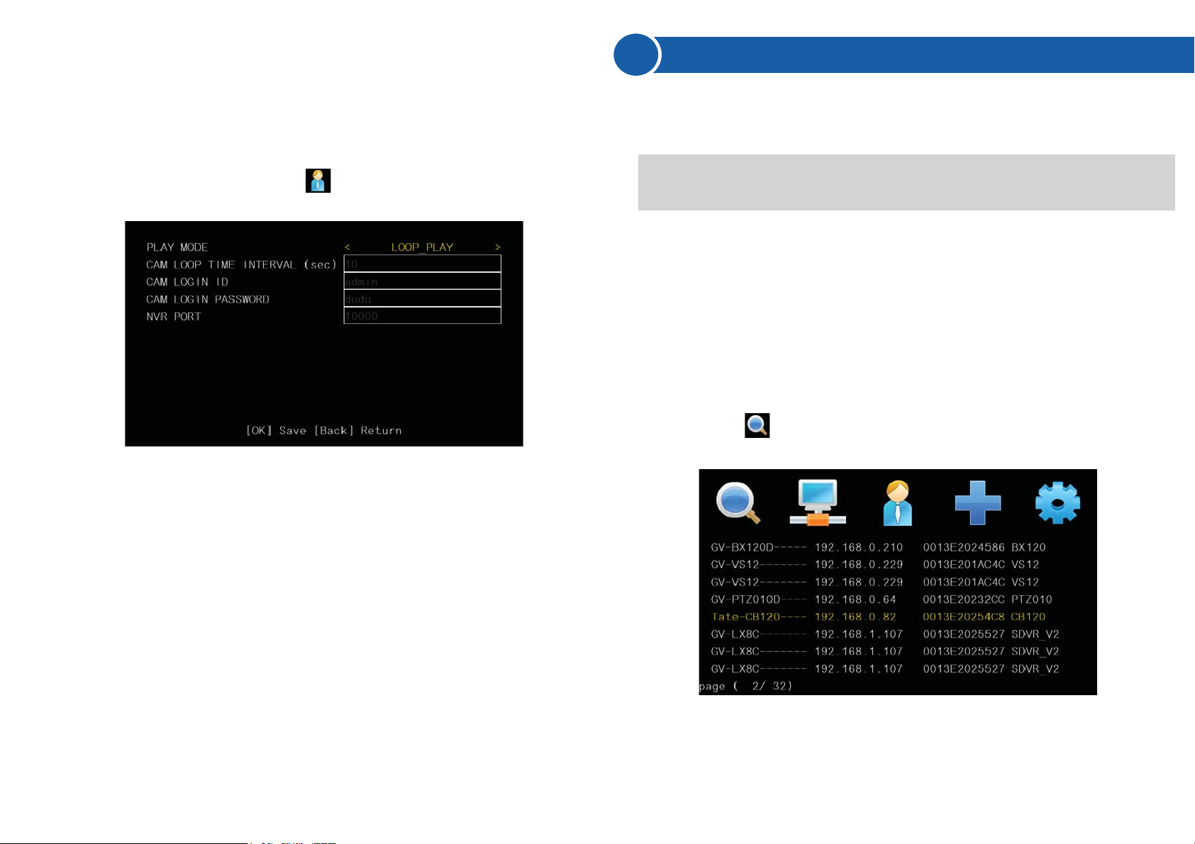
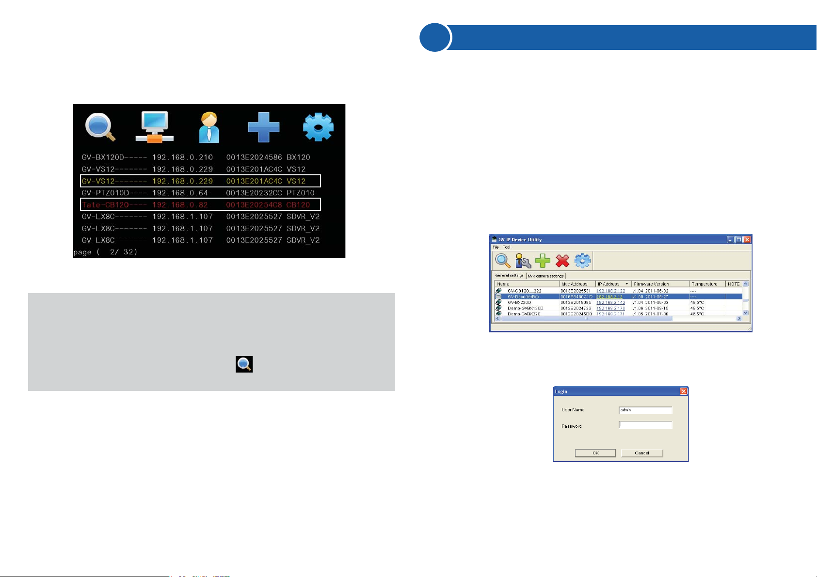
3. To move the cursor (shown in yellow), press the up and down arrow
keys. To select, press the right arrow key (shown in red).
4. Press the OK key, the selected channels will be displayed.
To add third-party IP channels, see 6. Displaying Channels Using GV IP
Device Utility in the Quick Start Guide.
To access the channels connected to GV-System, see 2.6 Displaying
Channels from GV-System in GV-IP Decoder Box and GV-Pad User’s
Manual on software DVD.
Note:
1. When the system idles over 30 seconds or resumes after power
interruption, the GV-IP Decoder Box will automatically display
channels based on the last successful settings.
2. Every time when the search function is performed, any
channels selected previously on the Device List will be unselected.
1. Make sure your GV IP devices, GV-System or third-party IP devices
are under same LAN with the GV-IP Decoder Box.
2. Install the GV IP Device Utility in a computer under the same LAN with
GV-IP Decoder Box. Double-click the GV IP Device Utility icon on the
desktop. The GV IP Utility window appears. It will automatically
search for all the channels from GV IP devices and from GV-System
under the same LAN.
3. Click on the IP address of your GV-IP Decoder Box and select
Connect Setting. This dialog box appears.
4. Type the ID and password of your GV-IP Decoder Box and click OK.
For detail, see step 3 in 4. Configuring the IP Address, ID and
Password. The Video Connection Setting window appears.
6Displaying Channels Using GV IP Device Utility
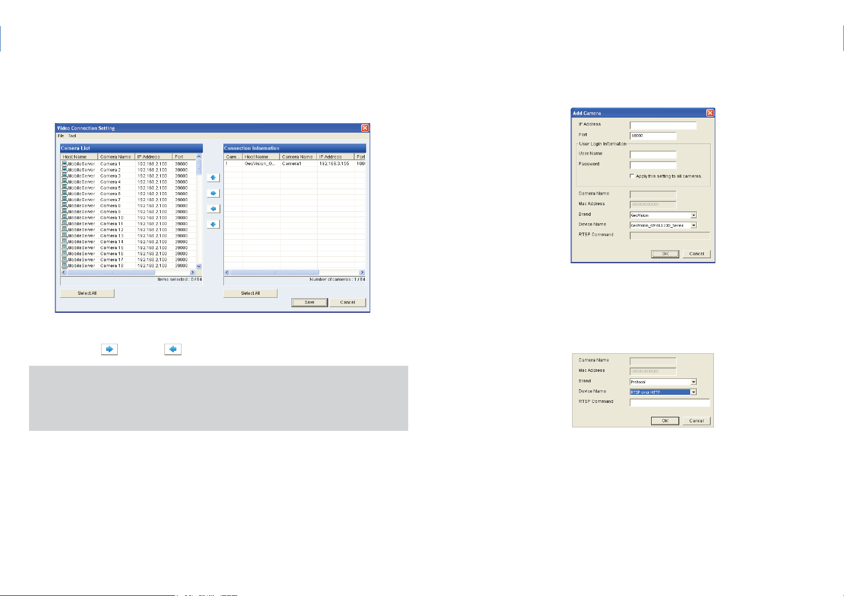
You may use the GV IP Device Utility to add and display channels from GV
IP devices, GV-System (through GV-Mobile Server) and third-party IP
devices through RTSP.

IMPORTANT: To select and connect to channels from GV-System, be
sure you have run and configured GV-Mobile Server. For setup steps,
see 2.6 Displaying Channels from GV-System in GV-IP Decoder Box
and GV-Pad User’s Manual on software DVD.
5. To connect to a GV IP device or devices from GV-System, use the
and right and left buttons to add or remove the device.
6. Right-click the added channel, select Edit and type the username and
password of the channel to log in. By default the login username and
password both are admin in all GV IP devices.
7. To add a third-party IP camera, follow the steps below.
A. Click Tool on the Video Connection Setting window, and select
Add Camera. This dialog box appears.
B. Type the IP address, user name and password of the device.
C. Select Protocol for Brand and one of the following RTSP type for
Device Name field using the drop-down lists, and type the RTSP
command. Refer to your third-party IP camera’s manual for this
information.
▪RTSP over HTTP: The RTSP protocol uses an HTTP port for
data streaming from the IP camera.
▪RTSP over TCP: The RTSP protocol uses a TCP port for data
streaming from the IP camera.
▪RTSP over UDP: The RTSP protocol uses a UDP port for data
streaming from the IP camera.
The IP devices under the same LAN with the GV-IP Decoder Box will be
listed in the Camera List column, and the connected channels will be listed
in the Connection Information column.

D. Click OK. The camera will be added to the list.
8. Use the up and down buttons to move the added channels
up and down the Connection Information list. The channels will be
displayed according to this order.
9. Click Save. The cameras on the Connection Information column will
be updated to the GV-IP Decoder Box and displayed on the monitor.
1. On the main menu, select and select the inserted storage device
under Storage.
2. Press the key to capture the image. A camera icon appears at
the top right corner of the monitor and 3 consecutive snapshots will be
taken and saved to the inserted storage device.
●you have at least 30 MB of space on your storage device.
●you have inserted a USB drive or SD card for storage.
●the storage type is correctly configured.
7Taking a Snapshot
The security administrators can capture images when events occur.
Snapshot images are automatically saved to an inserted storage device
such as a USB drive or SD card in JPEG format.
Before you start, be sure:
Otherwise, the error icon appears when attempting to capture an
image.
REC

9F, No. 246, Sec. 1, Neihu Rd., Neihu District, Taipei, Taiwan
Tel: +886-2-8797-8376 Fax: +886-2-8797-8335
http://www.geovision.com.tw
1. Copy the firmware file to the root folder of a USB storage device or a
SD card.
2. Connect the USB drive or SD card to the GV-IP Decoder Box /
GV-Pad.
3. On the setup menu, select and press OK. This window appears.
4. In the Firmware Update field, select USB or SD storage that stores
the firmware file.
5. Press OK. The firmware upgrade runs automatically, and the GV-IP
Decoder Box / GV-Pad will restart after the firmware upgrade is
completed.
●you have inserted a storage device (USB drive or SD card) and it
contains one firmware file only.
●the USB drive or SD card must have at least 100 MB of free
space.
8Pausing the Looped View
9Upgrading the Firmware
You can pause the looped view at a single channel. To pause the looped
view, press the key. A loop sign with a cross will appear on the
top-right corner of the display channel. To resume to the looped view, press
the key again.
We will periodically release the updated firmware on the website. You may
choose to update firmware locally using a USB drive or SD card
To upgrade the firmware remotely through GV IP Device Utility, see 3.6.2
Upgarding Firmware through GV IP Device Utility in GV-IP Decoder Box
and GV-Pad User’s Manual on software DVD.
Before you start, be sure:
Other manuals for GV-IP
6
This manual suits for next models
1
Table of contents
Other GeoVision Media Converter manuals

GeoVision
GeoVision GV-NET Card V3.2 User manual

GeoVision
GeoVision GV-IP User manual

GeoVision
GeoVision GV-NET Card V3.2 User manual

GeoVision
GeoVision GV-Cloud Bridge User manual

GeoVision
GeoVision GV-NET/IO Card v3.1 User manual

GeoVision
GeoVision GV-IP User manual

GeoVision
GeoVision GV-IP User manual

GeoVision
GeoVision GV-GVS2100 User manual

GeoVision
GeoVision GV-IP Decoder Box Series User manual