GeoVision GV-IP User manual

2015/05
English
DBV107-QG-A
Quick Start Guide
GV-IP Decoder Box and GV-Pad
V1.07
© 2015 GeoVision Inc. All rights reserved.
Thank you for purchasing GV-IP Decoder Box and GV-Pad. This guide is
designed to assist the new user in getting immediate results from the GV-IP
Decoder Box and GV-Pad. For advanced information on how to use the GV-IP
Decoder Box and GV-Pad, please refer to GV-IP Decoder Box and GV-Pad
User's Manual on software DVD.
Note: no SD/SDHC card slot or local storage function in Argentina

© 2015 GeoVision, Inc. All rights reserved.
Under the copyright laws, this manual may not be copied, in whole or in part,
without the written consent of GeoVision.
Every effort has been made to ensure that the information in this manual is
accurate. GeoVision, Inc. makes no expressed or implied warranty of any kind
and assumes no responsibility for errors or omissions. No liability is assumed
for incidental or consequential damages arising from the use of the information
or products contained herein. Features and specifications are subject to
change without notice. Note: no SD card slot or local storage function for
Argentina.
GeoVision, Inc.
9F, No. 246, Sec. 1, Neihu Rd.,
Neihu District, Taipei, Taiwan
Tel: +886-2-8797-8377
Fax: +886-2-8797-8335
http://www.geovision.com.tw
Trademarks used in this manual: GeoVision, the GeoVision logo and GV
series products are trademarks of GeoVision, Inc. Windows and Windows XP
are registered trademarks of Microsoft Corporation.
May 2015

Contents
1. Introduction....................................................................................................................2
1.1 Packing List ............................................................................................................................... 2
1.2 Optional Accessories .............................................................................................................. 3
1.3 Compatible Devices ................................................................................................................ 3
2. Overview.........................................................................................................................4
2.1 GV-IP Decoder Box ................................................................................................................... 4
Front View........................................................................................................................................ 4
Rear View ........................................................................................................................................ 5
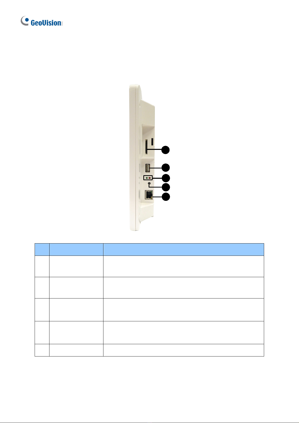
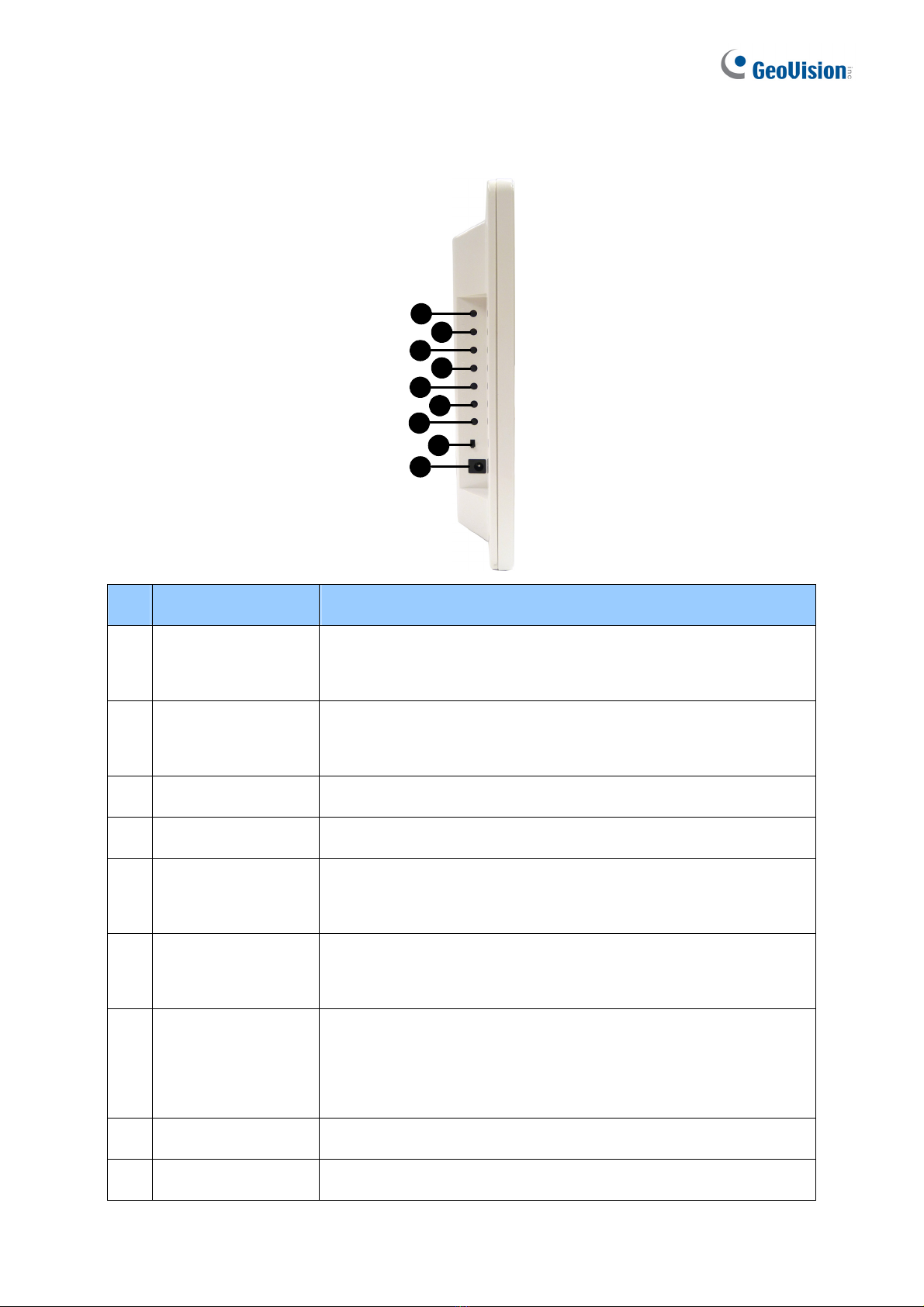
2.2 GV-Pad.................................................................................................................................... 6
Right Panel View ............................................................................................................................. 6
Left Panel View................................................................................................................................7
2.3 The IR Remote Control ........................................................................................................... 8
3. Connection...................................................................................................................10
3.1 GV-IP Decoder Box............................................................................................................... 10
3.2 GV-Pad.................................................................................................................................. 12
4. Setting up the Network................................................................................................13
4.1 Wired Network Connection ................................................................................................... 13
4.2 Wireless Network Connection............................................................................................... 14
5. Displaying Channels on the Monitor ..........................................................................15
5.1 Displaying Channels in Single View ..................................................................................... 15
5.2 Displaying Channels in Quad View....................................................................................... 17
6. Displaying Channels Using GV-IP Device Utility .......................................................19
6.1 Adding a GV-IP Device ......................................................................................................... 19
6.2 Adding a Third-party Device ................................................................................................. 22
7. Taking Snapshots ........................................................................................................24
8. Upgrading the Firmware..............................................................................................25
1

1. Introduction
Welcome to the GV-IP Decoder Box / GV-Pad Quick Start Guide. In the following sections,
you will learn about the basic installations and configurations of the GV-IP Decoder Box /
GV-Pad. For the details, see GV-IP Decoder Box and GV-Pad User’s Manual.
1.1 Packing List
GV-IP Decoder Box
1. GV-IP Decoder Box
2. IR remote control
3. AC/DC adapter (12 V, 3 A, 36 W)
4. Power cord
5. Software DVD
6. SD card
GV-Pad
1. GV-Pad
2. IR remote control
3. Magnetic hinge
4. Screw x 4
5. AC/DC adapter (12 V, 3 A, 36 W)
6. Power cord
7. Software DVD
8. SD Card
2

1.2 Optional Accessories
Optional devices can expand your GV-IP Decoder Box / GV-Pad’s capabilities and versatility.
Contact your dealer for more information.
Options Description
Wall Mount Kit The kit is used to mount the GV-IP Decoder Box to the wall.
VESA Monitor-Mount Kit The kit is used to mount the GV-IP Decoder Box to the back
of a VESA monitor.
GV-Joystick
The GV-Joystick facilitates focusing, zooming, panning,
tilting of GeoVision and third-party PT, PTZ and Speed Dome
cameras on GV-IP Decoder Box / GV-Pad.
GV-WiFi USB Adapter
The WiFi adapter is a plug-and-play device that provides
wireless connectivity to GV-IP Devices. It complies with
IEEE802.11 b/g/n (Draft 3.0) standards for wireless
networking.
1.3 Compatible Devices
The GV-IP Decoder Box / GV-Pad is compatible with:
1. GV-IP Camera, GV-Video Server and GV-Compact DVR using H.264 codec
2. Third-party IP devices that support H.264 and adhere to RTSP, ONVIF or PSIA
3. GV-Mobile Server
Note: Upgrade your GV-IP Devices to the latest firmware version if you encounter any
connection problems.
To decode and display non-H.264 IP channels or analog channels, connect the devices to
GV-System and access them through GV-Mobile Server.
3

2. Overview
2.1 GV-IP Decoder Box
Front View
123 4 5
No. Name Function
1 LED Indicators
The green LED indicates the system is ready for use.
The red LED indicates the power is supplied.
2 USB Connect to a GV-Joystick, a USB storage device or a GV-WiFi USB
adapter.
3 IR Built-in IR receiver to receive the IR signals from the IR Remote
Control.
4 Default
Reset the GV-IP Decoder Box to the default factory settings. Use a pin
to press the default button until the green LED fades. This will take
about 10 seconds. The system will then reset and reboot itself shortly.
5 SD Card Slot Connect to an SD card for local storage of snapshot and firmware
upgrade.
4

Rear View
123 4 5
HDMI
No. Name Function
1 Network Connect to the network.
2 HDMI Connect to an HDMI supported display device.
3 VGA Connect to a VGA monitor.
4 Power OFF/ON Switch the power on or off.
5 DC 12V Connect to power by using the supplied power adapter.
Note: The SPDIF and L/R ports are not functional.
5

2.2 GV-Pad
Right Panel View
1
2
3
4
5
No. Name Function
1 SD Card Slot Connect to an SD card for local storage of snapshot and
firmware upgrade.
2 USB Connect to a GV-Joystick, or to a USB storage device or a
GV-WiFi USB Adapter.
3 LED Indicators The green LED indicates the system is ready for use.
The red LED indicates the power is supplied.
4 IR
Built-in IR receiver to receive the IR signals from the IR Remote
Control.
5 Network Connect to the network.
6

Left Panel View
1
2
3
4
5
6
7
8
9
7
No. Name Function
1. MENU
zSwitch to the setup menu.
zLoad default: Press for 10 seconds to load default settings.
2 ENTER
zSave settings in the Setup Menu.
zDisplay selected channels.
3 UP Move the cursor up.
4 DOWN Move the cursor down.
5 LEFT
zMove the cursor left.
zUnselect a channel on the Device List.
6 RIGHT
zMove the cursor right.
zSelect a channel on the Device List.
7 STAND BY
Press to enter the Standby mode. In the standby mode, the
screen turns off to minimize power consumption. Press the key
again to enter the ON mode.
8 Power OFF/ON Switch the power on or off.
9 DC 12V Connect to power using the supplied power adapter.

2.3 The IR Remote Control
1 9
2
3
4
5
7
8
14
11
12
13
10
6
No.
8
Name Function
1 POWER Turn on or off the GV-IP Decoder Box / GV-Pad.
2
Numeric / Alphabetical /
Punctuation Marks /
ERASE keys
Enter numbers, alphabets or punctuation marks and erase
the entered characters.
3 BACK Back to the previous page in the Setup Menu.
4 Arrow
zMove up, down, right and left in the Setup Menu.
zRight arrow key: select a channel on the Device List.
zLeft arrow key: unselect a channel on the Device List.
5
PAGE UP /
PAGE DOWN
zGo to the previous / next page on the main screen.
zSwitch between the cameras on the looped view: press
the Loop Start / Stop key to stop the looped view, and
then press Page Up / Page Down to switch to the
previous / next camera.

No. Name Function
6 Division Extension Keys
(CH1 ~ CH4)
Extend the selected division (in Quad View mode) to
full-monitor display. Press the same key again to resume.
7 REC Capture a snapshot.
8
Capitalized
alphabetical keys
(A / B / C / D)
Specify a GV-IP Decoder Box / GV-Pad for IR remote control.
9 Loop Start / Stop
zStart or stop the looped view.
zDisplay and fix at a channel: press the Loop Start / Stop
key to stop the looped view, a numeric key and OK to
display and fix at the selected channel. Press 0and OK
to return to the last displayed channel.
10 MENU Switch to the setup menu.
11 OK
zSave settings in the Setup Menu.
zDisplay selected channels.
Switch among 8 resolution options.
1. Press Shift. The Green LED on the front panel flashes.
2. Press No. 0 ~ 7 for the desired resolution within 30
seconds.
0 : VGA_640 x 480
1 : VGA_1024 x 768
2 : VGA_1280 x 768
4 : HDMI_480p
5 : HDMI_720p
6 : HDMI_1080i
7 : HDMI_1080p
12 SHIFT
Note after the resolution is configured, the green LED will
fade and GV-IP Decoder Box / GV-Pad will reboot
automatically.
13 INFO Shows the camera name and total number of cameras under
display.
14 SEARCH Scan for available Access Points or wireless stations when
wireless network is selected.
9

3. Connection
3.1 GV-IP Decoder Box
Follow the steps below to connect the GV-IP Decoder Box:
1. Connect a display device to VGA or HDMI connector for video output.
2. Connect the device to LAN.
A. For wired network, connect to a standard network cable.
B. For wireless network, insert a Wi-Fi USB adapter.
3. Connect to power using the supplied power adapter.
4. Turn the Power switch to ON.
10

11
Note:
1. You can only connect the GV-IP Decoder Box to one display device through the HDMI or
VGA connector.
2. The default video output is set to VGA with 1024 x 768 resolutions. If you use an HDMI
monitor, be sure to change the output type. See 3.5 Configuring the Account, Storage
and Output Type in GV-IP Decoder Box / GV-Pad User’s Manual.
3. Optionally configure the device date and time. For details, see 3.5 Configuring the
Account, Storage and Output Type in GV-IP Decoder Box / GV-Pad User’s Manual.

3.2 GV-Pad
Follow the steps below to connect the GV-Pad:
1. Connect the device to LAN.
A. For wired network, connect to a standard network cable.
B. For wireless network, insert a Wi-Fi USB adapter.
2. Connect to power using the supplied power adapter.
3. Turn the Power switch to ON.
12

4. Setting up the Network
4.1 Wired Network Connection
Using wired network, the GV-IP Decoder Box / GV-Pad will be automatically assigned an IP
address by the DHCP server by default. To change the IP address to a fixed one, follow the
steps below.
1. Select the icon, select LAN Setting and press OK. This window appears.
2. Select NO in the DHCP section and enter a fixed IP address, subnet mask and DNS and
gateway.
3. Press OK. When the device is connected to the network, the IP address will be shown in
the Connected IP field.
13

4.2 Wireless Network Connection
A GV-WiFi USB Dongle is required to connect the device to wireless network. To establish a
wireless network connection, follow the steps below.
Note: The GV-IP Decoder Box / GV-Pad only supports dynamic IP address assignment
(DHCP) in a wireless network.
1. Select the icon, select WLAN Setting and press OK. This window appears.
2. Press the Search button to scan for available Access Points / wireless stations.
3. Select an Access Point / wireless station in the ESSID field and complete the settings
below.
ESSID: Shows the name of the Access Point. Press the left and right button to
select an Access Point.
Quality: Shows the connection quality on a scale of 1 to 100, with 100 being the
highest quality.
AuthMode: Select WEP Auto or WPAPSK according to the encryption setting of
the Access Point.
EncryMode: Select the Encryption Mode according to the encryption setting of the
Access Point.
Password: Type a password to match the Access Point. You can type up to 26
characters.
14
4. Press OK to connect to wireless LAN. When the device is connected to the network, the
IP address will be shown in the Connected IP field.

5. Displaying Channels on the Monitor
Use the search feature on GV-IP Decoder Box / GV-Pad to display channels from GV-IP
Devices, GV-Mobile Server and the third-party devices that adhere to ONVIF under the same
LAN.
Before you start, make sure the following:
zAll IP devices and GV-Mobile Server must be under the same LAN with GV-IP Decoder
Box / GV-Pad.
zThe NVR port (of GV-IP Decoder Box / GV-Pad) and VSS port (of GV-IP Devices) or
Command Port (of GV-Mobile Server) must be the same. The default NVR and VSS port
is 10000.
zThe ID and password for all IP devices and GV-Mobile Server must be the same. By
default, the ID and password of GV-IP Devices are admin.
Note: The Command Port of GV-Mobile Server is 55000 by default. To change the port
value, see 2.6 Displaying Channels from GV-Mobile Server in GV-IP Decoder Box / GV-Pad
User’s Manual.
5.1 Displaying Channels in Single View
15
1. Select the icon and press OK. The devices under the same LAN with the GV-IP
Decoder Box / GV-Pad appears on the Device List.

2. To select channels, press the up and down arrow keys and press the right arrow key. The
selected channels will be in red. To cancel the selection, press the left arrow key.
3. Press OK.
The selected channels will be displayed on the monitor and be looped at an interval of 30
seconds by default.
Note:
1. The camera view will display the message “Connection Lost”if the device does not have
the same ID and password with GV-IP Decoder Box / GV-Pad. To add a single IP device
with a different ID and password, see 2.4.3 Adding Channels Manually in GV-IP Decoder
Box / GV-Pad User’s Manual. To add multiple IP devices with different IDs and
passwords, see 6 Displaying Channels Using GV-IP Device Utility in the Quick Start
Guide.
2. The GV-IP Decoder Box supports a maximum resolution of 5 MP for single view. The
message “Resolution Error” appears on the monitor when the connected stream
exceeds this specification limit.
3. To change the looping interval, see CAM Loop Time Interval in 3.3 Configuring the Play
Mode in GV-IP Decoder Box / GV-Pad User’s Manual.
4. Every time when the search function is performed, any channels selected
previously on the Device List will be unselected.
16

5.2 Displaying Channels in Quad View
By default, the GV-IP Decoder Box / GV-Pad displays the camera channels in Single View. To
change the view mode to Quad View and add channels, follow the steps below.
1. Select the icon and press OK. In the Play Mode field, select SPLIT PLAY 4 and
press OK.
2. To search for IP devices, select the icon and press OK. The devices under the same
LAN with the GV-IP Decoder Box / GV-Pad appear on the Device List.
3. Select a channel and press a number from 1 to 4 to set the channel to one of the four
divisions on the Quad View for display. The selected channel will be in red, with a number
at the front. To reset the division, press the left arrow key on the channel and select
another number.
Corresponding position on Quad View to the number set for selected channel
1 2
3 4
4. Press OK.
The selected channels will be displayed on the assigned divisions on the Quad View, and the
channels in the same division will be looped at an interval of 30 seconds by default.
17

Tip: Press the CH1 ~ CH4 keys to extend a division to full-monitor view (in its Quad View
resolution) and press the key again to resume.
Note:
1. The GV-IP Decoder Box supports a maximum resolution of 1280 x 720 for each division
under quad view. The message “Resolution Error” appears on the monitor when the
connected stream exceeds this specification limit.
2. Refer to the note under 5.1 Displaying Channels in Single View in the Quick Start Guide.
18
Other manuals for GV-IP
6
This manual suits for next models
1
Table of contents
Other GeoVision Media Converter manuals

GeoVision
GeoVision GV-IP User manual

GeoVision
GeoVision GV-NET Card V3.2 User manual

GeoVision
GeoVision GV-IP User manual

GeoVision
GeoVision GV-Cloud Bridge User manual

GeoVision
GeoVision GV-NET Card V3.2 User manual

GeoVision
GeoVision GV-NET/IO Card v3.1 User manual

GeoVision
GeoVision GV-IP User manual

GeoVision
GeoVision GV-IP Decoder Box Series User manual

GeoVision
GeoVision GV-GVS2100 User manual