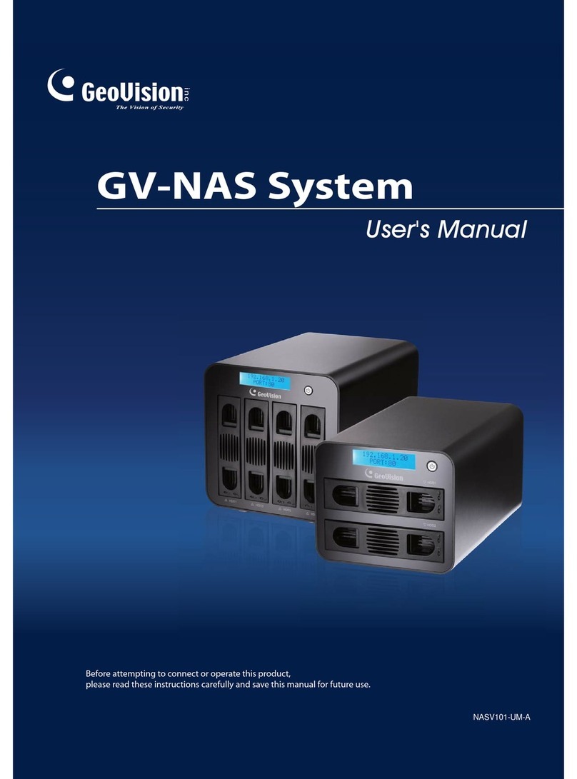
GeoVision GV-Storage System User manual

Quick Start Guide
This guide is designed to assist the new user in getting immediate results from the GV-Storage System. For advanced
information on how to use the GV-Storage System, please refer to GV-Storage System User’s Manual.
© 2008 March GeoVision, Inc. All rights reserved. SRV1-QG-1
GV-Storage System
RoHS
The Vision of Security

GV-Storage System can work in conjunction with these GV products to save data:
GV-System version 8.2, GV-Video Server version 1.4, GV-Compact DVR and GV-NVR.
Note:
Working with GV Products
GV-System version 8.2 and GV-NVR provides Backup Server and Backup
Viewer functions. Backup Server allows you to back up recorded data to
GV-Storage System automatically, while Backup Viewer allows you to access
the data from any computer. For details see Surveillance System User’s
Manual.
For the connection with GV-Video Server and GV-Compact DVR, see their own
user’s manuals.
GV-System / NVR
with Backup Server
GV-System / NVR
with Backup Server
GV-Compact DVR
GV-Video Server
Backup
Viewer
Gigabit
Ethernet
GV-Storage System
AC Power Cord x 2
Lock Key x 2
Self-Stick Rubber Pad x 4
GV-Storage System User’s Manual on software CD
GV-Storage System Quick Start Guide on software CD
Package List
Package List
Check Certification List in Appendix to confirm the hardware setting is fully supported
A DVR server of GV-System version 8.2 with a network interface card (NIC)
CAT 5e or CAT 6 LAN cables for one management port and two iSCSI data ports
(CAT 6 cable is recommended for best performance)
Prepare storage system configuration plan
Network information of management and iSCSI data ports, including static IP
addresses, subnet mask, and default gateway
A Gigabit Layer 2 or Layer 3 managed stackable switch
CHAP security information, including CHAP username and secret (Optional)
Before You Begin
Before You Begin
Before starting, prepare the following items:

Recommended Hard Drive
Usage Notice
Usage Notice
Please pay attention to the following notice when you use the storage system.
To avoid compatibility issues between the storage system and hard drives, we
strongly suggest you use Seagate Barracuda ES series drives. For details on drive
models, see Certification List in GV-Storage System User’s Manual.
Replacing Hard Drives
Don’t turn off the power of the drive bay when replacing the hard dive, otherwise
RAID failure could occur.
Before Power Off
It is better to execute “Shutdown” through LCD panel menu to flush the data from
cache to physical disks before power off.
UDV (User Data Volume) Restriction
Don’t assign the same UDV to more than one DVR host for recording usage;
otherwise you may suffer data lost or corrupt.
Initiator Node Name Restriction
The Initiator node name only accepts lower-case letters. Use lower-case letters for
Host name in the storage system, otherwise you cannot establish the connection
between the storage system and DVR.
Order of Hard Drive Slots
Remember the order of hard drive slots on the storage system. When you see the
warning message “Error: Disk, <slot> is failed”, remove the failed hard drive in the
correct slot. If you remove the hard drive in the wrong slot, you could suffer
data loss.
1 2 3 7 84 5 6
For details see 3.3 Installing on the Network in GV-Storage System User’s Manual.
Connect the unit’s management port to the network on which you will manage the
storage system. The default IP address of the management port is
http://192.168.0.200
Using LAN cables, connect the unit’s iSCSI data ports to a Gigabit switch.
Install hard drives.
Using the two provided power cords, connect the unit’s two power supplies to a
different power source/circuit.
1.
2.
3.
4.
Step 1 Install on a Network
1
1
Management
LAN port
Management
server
Two iSCSI data ports
Gigabit switch
DVR/NVR DVR/NVR DVR/NVR DVR/NVR
Turn on the two power switches on the rear panel.
Turn on the main power switch on the front panel.
Check status of powering on to ensure that everything is running smoothly.
1.
2.
3.
Step 2 Turn on the Power
1
2
Power Supply LED: The two LEDs on the rear panel should turn green.
GigaLAN Detect LED: The two LEDs on the front panel should turn green.
Drive Bay LED: Power LEDs for all drive bays containing hard drives should
light up.
Step 3 Login
Step 3 Login
1
3
Rear Panel
Front Panel
Power Supply LED
Power Switch
RESET
HD1
HD2
HD3
GigaLAN
Detect LEDs
Power Button
and LED
Main Power Siwtch
Front Panel for HDD 1 to 6 Front Panel for HDD 7 and 8
Power
Button
Power
LED
On the management server, open the browser and enter the default IP:
http://192.168.0.200
Click any function on the left side of window; enter the default login name admin and
password admin.
Step 4 Create a RAID Volume
1
4
There are two methods to create a RAID volume.
Before creating a volume, please make sure all hard disks are installed in the system
properly by selecting / Volume config / Physical disk. The status of hard disks should
show “Good”.
(Figure: Eight physical disks are inserted to slot 1 to slot 8. The size of each disk is 372GB.
The status of the disks is good.)
If only one host connects to the storage system, you may use the Quick Install
function to create a volume quickly. For this, follow the instructions in Part I.
If more than one host connects to the storage system, you need to create an
independent volume for each host for data storage. For this, follow the instructions
in Part II.
1.
2.

Part I: Use “Quick Install”
Select Quick install, and choose RAID level from the drop-down list. Click Next.1.
(Figure: the maximum volume size is 2606GB, and 1 LUN (No. 0) is attached.)
(Figure: a RAID 5 user data volume with the UDV name “QUICK13217”, named by the
system itself, with the total available volume size 2606GB, and attached with 1 LUN.)
Click Confirm if all setups are correct. Then a page with the “User data volume” is
created.
Note: The UDV (user data volume) created by “Quick Install” is accessible by
every host. Access control of host would show as a wildcard “*”. To see and
modify the volume, select \ Volume config \ Logical unit.
Note: If using OS such as Windows XP, Windows 2000 or Windows Vista 32
bits, click Cancel when this warning message pops up "LBA 64 Support?
Choose Cancel. It will change the sector size to 4K. The maximum capacity is
up to 16 TB. This volume can not be Dynamic Disk."
3.
Part II: Create an independent volume for each host
In this example, three UDVs (user data volume) are created in one VG, and assigned for
three different hosts DVR system, Video Server and Compact DVR for data storage.
Create VG (Volume Group).1.
Select / Volume config / Volume group.
Click Create.
Type a VG Name, select a RAID level, press Select PD to choose the RAID
PD slot(s), and then press Next.
Check the outcome. Press Confirm if all setups are correct.
A VG has been created.
(Figure: Create a RAID 5 with 8 physical disks, named “Storage”. The total size is
2606GB. Because of no related UDV there, free size still remains 2606GB.)
a.
b.
c.
d.
e.
Type Volume size and select a LUN number. By default, the maximum volume size
is shown. Click Next.
2.

Attach LUN to UDV.3.
Done. The RAID volumns have been created.4.
In / Volume config / User data volume, select a UDV and press Attach.
Enter Host, which is an initiator node name for access control. Choose
Permission to Read-write for data storage, and then click Confirm.
A LUN and host have been created.
Do one more time to create another LUN and host.
a.
b.
c.
d.
(Figure: UDV-1 is attached to LUN 0 which only initiator node named “dvrsystem” can
access. UDV-2 is attached to LUN 1 which only initiator node named “compactdvr” can
access. UDV-3 is attached to LUN 2 which only initiator node named “videoserver” can
access.)
Create UDV (User Data Volume).2.
Select / Volume config / User data volume.
Click Create.
Type a UDV name, choose a VG Name and enter a size to the UDV. Decide the
stripe height, block size, read/write mode and set priority. Finally click Confirm.
A UDV has been created.
Do one more time to create another UDV.
a.
b.
c.
d.
e.
(Figure: Create three UDVs named “UDV-1”, “UDV-2” and “UDV-3”, related to “Storage”
VG. The size of “UDV-1” is 1000GB, the size of “UDV-2” is 800GB and the size of
“UDV-3” is 806GB. The status of these UDVs are online, write back, high priority with
cache volume 383MB. “UDV-1” is initialing about 2%. There is no LUN attached.)

The DVR host needs to run and set up the iSCSI Initiator to request access for storage.
The Microsoft iSCSI Software Initiator is available as a free download from Microsoft
Download Center.
Step 5 Configure Initiator on DVR Host
1
5
Run Microsoft iSCSI Initiator.1.
To add target portals, click the Discovery tab and click Add.2.
Type the IP address of GV-Storage System, and click OK. By default, the IP address
of iSCSI data port 1 is 192.168.1.1, and iSCSI data port 2 is 192.168.2.1. If both data
ports are used for connection to the DVR host, add two data port IPs respectively.
3.
Click the Targets tab and click Log On.4.
Select Automatically restore this connection when the system boots and click
Advanced.
5.
Select Local Adaptor to Microsoft iSCSI Initiator, select Source IP to the host IP
and select Target Portal to iSCSI data port 1. If the CHAP authentication is
enabled at the storage system, select CHAP logon information and type a valid
username and target secret (password). Click OK.
6.
(Figure: In this example, we added iSCSI data port 1 of 192.168.0.170 and iSCSI data port
2 of 192.168.0.171 as target portals.)
(Figure: In this example, the DVR IP address is 192.168.0.150. The iSCSI data port 1 is
192.168.0.170)

When the connection with the storage system is established, the status changes
into “Connected”. At this step, you can already use the iSCSI disk by the operation
similar to the case to increase a local disk. Refer to step 13.
If the iSCSI data port 2 is used for connection to the DVR host, click Details and
keep on the following steps.
7.
Click Connections.8.
Click Add.9.
Click Advanced.10.
Select Target Portal to iSCSI data port 2, set up the CHAP authentication if
necessary and click OK.
11.
Now you can see the status of both Source Portals displays “Connected”. Click
Apply.
12.
(Figure: In this example, the iSCSI data port 2 is 192.168.0.171.)

When connecting to the iSCSI disk at the first time, it is necessary to format it as
well as a local disk. Run Windows Disk Management to configure a disk. Note the
settings of the formatted partition should be Basic disk storage and NTFS file
system.
For details see Chapter 7 About iSCSI Initiator in GV-Storage System User’s Manual.
13.
Click the Windows Start button, point to Programs, click GV folder and select Hot
Swap HDD Tool.
1.
Right-click the iSCSI drive, and select Add for recording.
Select a storage group from Add to drop-down list. Click OK to automatically
configure the iSCSI drive to the recording path.
2.
3.
To verify the iSCSI drive is added successfully, check if the status of the drive
displays “Standby”. Or in GV-System, click the Configure button, point to General
Setting, select System Configure, click the Set Location button, and then select
Storage Group Folder to confirm the new recording path.
4.
Step 6 Add the iSCSI Disk to Recording Path
1
6
After formatting the iSCSI disk, you can add it to the recording path and use it for
recording.
To automatically back up recorded files to the storage system, and to access the files from
any computer, see Backup Server and Backup Viewer respectively in Surveillance System
User’s Manual.
Table of contents
Other GeoVision Network Storage Server manuals
Popular Network Storage Server manuals by other brands

InWin
InWin Cobra IW-RS424-07 user manual

HPE
HPE Synergy 12Gb SAS Storage Maintenance and service guide

Premio
Premio OSS424-UN quick guide

IBM
IBM TotalStorage NAS 300 Service guide

TRENDnet
TRENDnet TS-S402 - Diskless SATA I/II Network Attached Storage... user guide

Seagate
Seagate Business Storage 1-Bay NAS datasheet

Iomega
Iomega 33244 - NAS 200d/750GB With Print Server Quick installation guide

AIC
AIC SB110-CT user manual

LaCie
LaCie 301417U - Big Disk Network NAS Server user manual

Infortrend
Infortrend EonNAS 3000 series Hardware manual

HP
HP NetStorage 6000 Storage Upgrade

Buffalo
Buffalo TeraStation WSS WSH5010N6 user manual