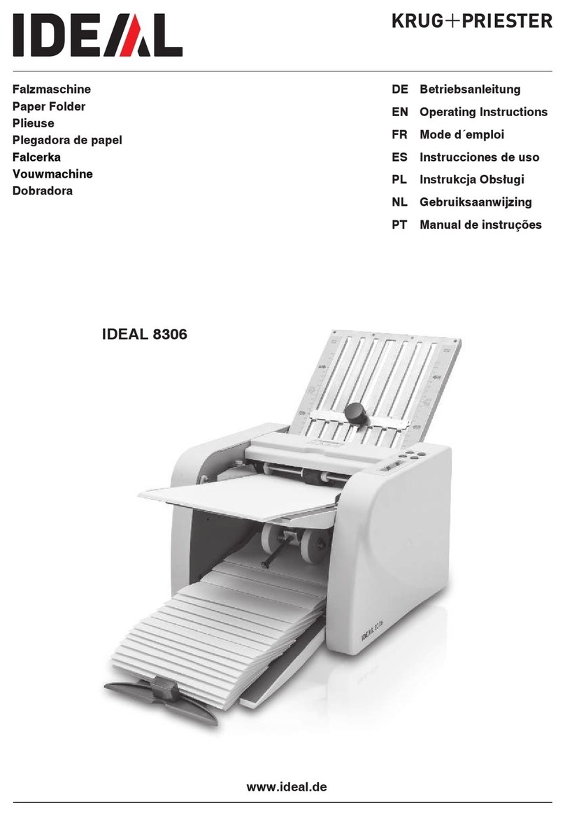
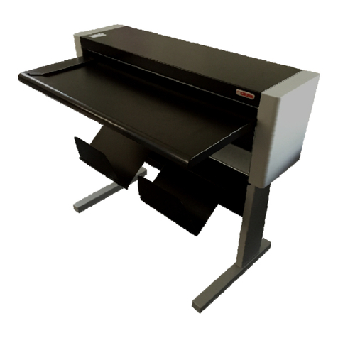
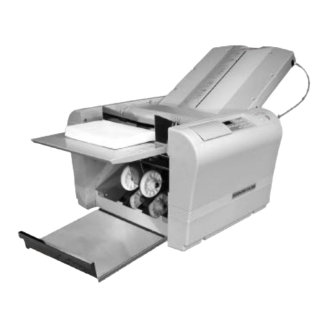
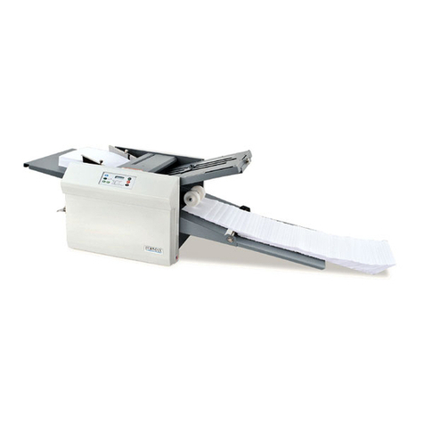
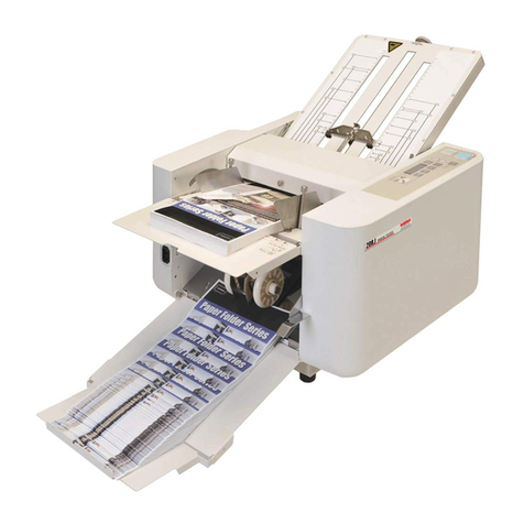
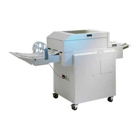
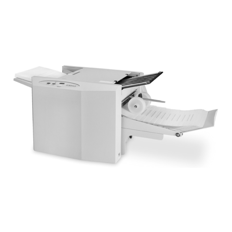
GERA LadyBird I User manual

LadyBird I Folder
Service Manual
D860101X
March 2014

Ladybird I Folder March 2014 Intro
Service Manual I
Intro
ABOUT THIS DOCUMENTATION..................................................................................... II
DOCUMENTATION DESIGN AND PURPOSE...............................................................................II
SERVICE DOCUMENTATION REVISIONS..................................................................................II
ORGANIZATION................................................................................................................... II
HOW TO USE THIS DOCUMENTATION ........................................................................III
INTRODUCTION .....................................................................................................................III
SECTION 1: SERVICE CALL PROCEDURES ..............................................................................III
SECTION 2: REPAIR ANALYSIS PROCEDURE ..........................................................................III
SECTION 3: FOLD QUALITY...................................................................................................III
SECTION 4: REPAIR AND ADJUSTMENT..................................................................................III
SECTION 5: PARTS LIST.........................................................................................................III
SECTION 6: GENERAL PROCEDURES......................................................................................III
SECTION 7: WIRING DATA ....................................................................................................III
OTHER INFORMATION .....................................................................................................III
THE USE OF CAUTION,WARNING,AND NOTE STATEMENTS..................................................III
REFERENCE SYMBOLOGY ..............................................................................................IV
INTRODUCTION TO REFERENCE SYMBOLOGY....................................................................... IV
ACRONYMS .......................................................................................................................... IV
REFERENCE SYMBOLS.......................................................................................................... IV
SCHEMATIC SYMBOLS.......................................................................................................... IV
AC AND DC VOLTAGE REFERENCES.................................................................................... IV
ABBREVIATIONS................................................................................................................... IV
REFERENCE SYMBOLOGY ................................................................................................V

Ladybird I Folder March 2014 Intro
Service Manual II
ABOUT THIS DOCUMENTATION
Documentation Design and Purpose
This Service Documentation contains diagnostic, repair, and maintenance information, that
has been designed to assist the Service Representative in the isolation and repair of faults,as
well as,maintenance of the GERA Ladybird Folder.
This documentation assumes that the user is familiar with the electrical and mechanical
standards that are commonly used throughout the industry, as well as,certain GERA design
and documentation conventions. This documentation also assumes that the user has
successfully completed any required training and is familiar with the use of any special tools
that are required to service this product.
Service Documentation Revisions
This service documentation may be subject to periodic revision in order to reflect any
changes in electrical or mechanical hardware, as well as any possible additions or corrections
necessary to ensure the technical accuracy of the documentation.
ORGANIZATION
This documentation is divided into eight sections. In addition to the Introduction, the
following sections are contained within this documentation.
Section 1 - Service Call Procedures
Section 2 - Repair Analysis Procedure
Section 3 - Fold Quality
Section 4 - Repair and Adjustment
Section 5 - Parts list
Section 6 - General Procedures
Section 7 - Wiring Data
A detailed description of the information contained within each section of the service
documentation will be found in the following subsection

Ladybird I Folder March 2014 Intro
Service Manual III
HOW TO USE THIS DOCUMENTATION
Introduction
This section provides the Service Representative with information pertaining to the
organization and use of this service documentation, and includes the following supportive
reference data:
Reference Symbology
Signal Nomenclature
DC Voltage Range Specifications
Section 1: Service Call Procedures
This section is used by the Service Representative as a structured process for determining the
type and sequence of actions that are performed during a service call. The Service Call
Procedures section is designed to assist in the effective recognition of machine symptoms
and problems, as well as,providing instructions for the maintenance and corrective actions
that are required to return the machine to the full operating condition.
Section 1 of this service documentation is the entry level for all service calls. The Service
Representative should begin each service call with the Initial Actions/Systems Checks
procedure found in Section 1.
Section 2: Repair Analysis Procedure
Section 2 of this documentation contains the Repair Analysis Procedures (RAPS) necessary
to repair all faults other than the folds faults. The Service Representative will be referred to
this section from some other section of this documentation during the service call. When a
machine defect or fault has been resolved by using a RAP, the Service Representative should
immediately return to the point in the service call from which section 2 was entered.
Section 3: Fold Quality
This section contains the Fold Quality Repair Analysis Procedure used to diagnose fold
quality defect problems within the Ladybird Folder.
Section 4: Repair and Adjustment
This section contains all repair and adjustment procedures for the machine. Repairs (REPS)
and adjustments (ADJS) are identified by the use of a standard chain prefix number.
Section 5: Parts List
This section contains a list of spare parts for the machine. All parts list page reference
numbers begin with the letters 'PL', followed by a prefix number, a decimal point, and a
sequential number used within the subsystem.
Section 6: General Procedures
This section contains procedures and Information of a general nature that apply to the
machine. The General Procedures subsection contains frequently used procedures that relate
to the diagnosis, the set-up, or the operation of the machine.
It also includes specific information that is pertinent to the operation of the machine, but will
not be found in any other part of the service documentation. This information may include
product codes, environmental operating data, installation space requirements, paper and
electrical specifications. This subsection may also contain information regarding
supplemental tools and supplies, general service notes, a glossary of commonly used terms,
and a Change Tag Index of authorized machine modifications and retrofits.
Section 7: Wiring Data
This section contains support information to assist in the electrical diagnosis of machine
problems and is a central location for electrical wiring diagrams. This section is used in
conjunction with other diagnostic or maintenance procedures that are contained in other
sections of the service documentation..
OTHER INFORMATION
The Use of Caution, Warning, and Note statements
Information relative to the completion of a task in a safe or thorough manner will be supplied
in the form of a Caution, a Warning, or a Note statement. These statements are found
throughout the service documentation.
Cautions, Warnings, and Note statements appear before the steps to which they apply. These
statements should be read before continuing to the next step in a procedure.
The definition of a Caution, Warning, or Note is as follows:
Caution - A Caution statement indicates an operating or maintenance procedure, practice, or
condition that, if not strictly observed, could result in damage to, or destruction of,
equipment.
Warning - A Warning statement indicates an operating or maintenance procedure, practice,
or condition that, if not strictly observed, could result in personal injury or loss of life.
Note - A Note statement indicates an operating or maintenance problem, practice, or
condition that is necessary to accomplish a task efficiently.
The Use of Acronyms, Abbreviation, Specific or Unique Terms, and Conventions
A list of acronyms and abbreviations used in this service documentation will be found In the
Reference Symbology subsection, contained elsewhere in this section.
Ladybird I Folder March 2014 Intro
Service Manual IV
REFERENCE SYMBOLOGY
Introduction to Reference Symbology
This section describes and defines the various acronyms, abbreviations, reference symbols,
Signal Nomenclature, and AC and DC power specifications. The following is a description
of some of the terms found in this section:
Acronyms
Acronyms are used throughout this service documentation to denote common terminology.
Although some acronyms may be unique to this product, most acronyms used in this
document are known throughout the service industry. Table 1 lists the acronyms that are
found in this service documentation.
Reference Symbols
Reference symbols consist of various icons used in this documentation to denote supportive
data that can be found in other sections of this documentation. The purpose of these symbols
is to inform the Service Representative of procedures, adjustments, or other information that
is important for successful diagnosis and repair.
Schematic Symbols
These symbols represent various electrical and mechanical components or devices that are
commonly found In GERA equipment. These symbols are included as an aid to
understanding the representations used in the Circuit Diagrams (CDs).
AC and DC Voltage References
The expected AC and DC voltage levels found in this machine are defined in this section.
These specifications represent the expected range for AC (machine Input power source) and
DC (machine internal power supplies) voltages that are encountered during normal operation
Abbreviations
Table 2 lists the electrical wire colors that are identified in this service documentation and
reflects the use of standardized abbreviations.
Acronym Definition
AC Alternating Current
ACH Alternating Current High
ACN Alternating Current Neutral
AMP Ampere
BSD Block Schematic Diagram
BTU British Thermal Unit
CD Circuit Diagram
FQ Folding Quality
DC Direct Current
ESD Electrostatic Discharge
HFSI High Frequency Service Item
LED Light Emitting Diode
PL Parts List
PWB Printed Wiring Board
RAP Repair Analysis Procedure
VAC Volts Alternating Current
VDC Volts Direct Current
ADJ Adjustment
Table 1 General Acronyms
Abbreviation Wire Color
BLK black
BLU blue
BRN brown
GRAY gray
GRN green
G/Y green / yellow
ORN orange
PINK pink
RED red
VIO violet
WHT white
YEL yellow
Y/G yellow / green
Table 1- 1 Wire Color Abbreviation

Ladybird I Folder March 2014 Intro
Service Manual V
REFERENCE SYMBOLOGY
Note, adjustments, and parts list, support the checklists and the RAP information. The
symbols that refer to this supportive data are shown below
Note
1
This symbol is used to refer to notes usually found on the same page.
Adjustment
This symbol refers to an adjustment procedure located in Section 4 of this
Service Documentation. The number adjacent to the symbol indicates the
number that is assigned to that adjustment
Voltage Source
This is an indication of the source voltage that is used for operation of a
component.
Status Code
C1.01
A box in the control logic section of the circuit diagram represents the
status code.
Flag
2
This symbol indicates an area of a Circuit Diagram that you should check.
Component Control
[0403]
The code [0403] is an example of an output diagnostic test.
Switches and Relay Contacts
Safety interlock switch that is open
Safety interlock switch that is closed.
Switch/relay contacts with momentary contacts shown normally open.
Switch/relay contacts with momentary contacts shown normally closed.
Connectors numbering
This symbol indicates the numbering of the connector pins
Parts List
PL 1. 1 Reference to an Exploded Drawing - The spared component is found in the
particular drawing in the Parts List.
WARNING
This WARNING alerts users to areas of the product where there is the
possibility get an electric shock
WARNING
This WARNING alerts users to areas of the product where there is the
possibility of personal injury
CAUTION
!
This CAUTION alerts user that a wrong operation could damage the Folder
NOTE
This symbol alerts user to pay attention in the operation described
CAUTION
ESD
This symbol Is used when components In the copier are susceptible to
damage from electrostatic discharge. Observe ESD procedures to avoid
component damage.
The Signal Flow
This symbol indicates an interrupted signal in a horizontal direction.
Ground
This symbol indicates a machine ground.
Connector
5
JXX Plug I Jack Connector and pin number
Motor
Motor
Thermistor
Thermistor Bead, used to sense temperature

Ladybird I Folder March 2014 Intro
Service Manual VI
Driver
A Driver that is used to switch on DC components
Solenoid
Clutch or Solenoid.
Tag Information
1
A TAG number within a circle and pointing to one or more item number,
shows that the part has been changed by the TAG number within the circle.
1
A TAG number within a circle without apex shows that the entire drawing
has been changed by the TAG number within the circle.
1
A TAG number within a circle having a shaded bar and pointing to one or
more item number, shows that the configuration of the part shown is the
configuration before the part was changed by the tag number within the
circle
1
A TAG number within a circle having a shaded bar without apex shows
that of the entire drawing was the configuration before being changed by
the tag number within the circle
Signal Nomenclature
The signal is named to imply the condition of the machine when the signal is available. For
example:
Step Motor On (L) +5 Vdc
1. STEP MOTOR ON = Signal Name
2. (L) = logic State when the signal is available in it's named state. In this case, the
signal is low when the Main Motor is energised.
3. +5 VDC = Logic level when the signal is High.
DC Voltage Levels
DC Voltages should be measured between the test point and the machine frame, unless
instructed otherwise.
The table below shows the value of the voltages.
Voltage Specification
+12 VDC H +2VDC
L +12VDC
+24 VDC
+48 VDC
Table 2
Logic Voltage Levels
Measurements of logic levels must be made with reference to the specified ground point,
unless some other point is referenced in a diagnostic procedure.
Nominal Voltage Logic State Actual Voltage Ranges
+5 VDC H +4.8 VDC to +5.2 VDC
Table 3

Ladybird I Folder March 2014
Service Manual 1-1 SERVICE CALL PROCEDURE
1. Service Call Procedure
1.SERVICE CALL PROCEDURE .................................................................................1-1
SERVICE CALL PROCEDURES ..................................................................................... 1-2
INITIAL ACTION ............................................................................................................. 1-2
FOLDER REGISTRATION....................................................................................................... 1-3
SYSTEM CHECKOUT...................................................................................................... 1-3
CSE CALL ESCALATION...................................................................................................... 1-3

Ladybird I Folder March 2014
Service Manual 1-2 SERVICE CALL PROCEDURE
SERVICE CALL PROCEDURES
Introduction
Initial Action/System Checks
This diagram is designed to identity and classify the folder problem and to refer you to
the appropriate Repair Analysis Procedure (Section 2) or Fold Quality (Section 3).
Final Action is designed to ensure that the folded print is transported correctly to
ensure that fold quality is within specification.
Call Flow Chart
INITIAL ACTION
Initial Actions / System Check out
Identity and classify the folder problem by using
RAP and Fold Quality Section
Perform: RAP, REP, ADJ
Final Actions
.
FOLD QUALITY
PROBLEMS:
Section 3,
Fold Quality
FOLD
QUALITY
SELECTION
INDICATION:
-Go to the
Generic RAP
OTHERS
PROBLEMS
FOLDER
MESSAGES:
•Alarm Status
describing a folder
status after a POST
•Error Alarm
describing what fold
process error occurs
by fold a copy
STATUS
INDICATORS
A
SK THE OPERATOR TO DESCRIBE THE
PROBLEM
ENSURE THAT THE POWER CORD IS
CONNECTED.
ENSURE THAT THE CUSTOMER’S
CIRCUIT BREAKER IS NOT TRIPPED
FOLD TEST PRINT IN ORDER TO VERIFY
THE PROBLEM IF THE PROBLEM STILL
EXISTS, THEN CONTINUE.
IF PROBLEM DOES NOT EXIST, DO
A
SYSTEM CHECKOUT AND REPAIR ANY
FAULTS DETECTED
-Go to the
Section 2 Contents
-Go to the

Ladybird I Folder March 2014
Service Manual 1-3 SERVICE CALL PROCEDURE
FOLDER REGISTRATION
After the folder installation procedure is performed it is mandatory to perform the Folder
Registration.
At the end of the Installation Procedure in Service Manual Section 6 CSE must perform the
Folder Registration, these actions provided as a convenience to insure that all the elements of
the installation procedure are completed.
The Folder Registration Form can be completed on line at
http://www.gera.it/GERA%20folder%20registration.htm and is required to:
Order Spare
Activate Warranty
Contact Tech support with the online Problem Report Form
SYSTEM CHECKOUT
Procedure
Run and fold the following sizes by:
ISO ANSI ARCH
A3 B B
A2 C C
A1 D D
A0 E E
Folded prints are delivered to the output tray.
Y N
Refer to the Initial Action in order to classify the problem and begin your repairs.
Evaluate the print folding. The folding quality is acceptable.
Y N
Go to Section 3, Fold Quality.
Close the Call.
CSE CALL ESCALATION
To enter the Call Escalation Flow the Customer Service Engineer must first:
1. Make sure that the Product has been registered on the GERA web site and store a copy
of the form in the folder. This will enable
Ordering Spares
Activate Warranty
Contact Tech support with a Problem Report Form
2. Get the Gera Folder serial number
3. Evaluate the problem using Section 3 Fold Quality or Section 2 RAP in the Service
Manual and adjust or repair as necessary
4. If problem is not resolved, open a call to GERA by using the Problem Report Form on-
line using this web link http://gera.it/tech_support_file/tech.html
5. Fill the on line PRF with the required details and send it to GERA SERVICE TEAM by
pressing Submit button.

Ladybird I Folder March 2014 REPAIR ANALYSIS PROCEDURE
Service Manual 2-1
2. Repair Analysis Procedure
2.REPAIR ANALYSIS PROCEDURE 2-1
How to read this section 2-2
Sensor default status chart 2-2
STATUS MESSAGE RAPS 2-1
TWO GREEN LED LIT ON TOGETHER 2-1
FAN FOLDER UPPER POCKET SENSOR COVERED RAP (ALL) 2-1
FAN FOLDER LOWER POCKET SENSOR COVERED RAP (ALL) 2-2
alarm status RAPS 2-2
FOLDER ENTRANCE ALARM RAP (ALL) 2-2
FAN FOLDER ALARM RAP (ALL) 2-3
CROSS ALARM RAP (ALL) 2-3
GENERIC RAPS 2-4
Generic RAP 1 2-4
POWER OFF RAP 2-4

Ladybird I Folder March 2014 REPAIR ANALYSIS PROCEDURE
Service Manual 2-2
HOW TO READ THIS SECTION
This section provides information on how to understand the correct operation of input
sensors, motors, solenoids, clutches and troubleshoot and identify folder problems.
This section identifies typical folder messages.
•STATUS Message : each time the folder is powered up the folder logic provides a Power
On Self Test (POST). This operation when completed (3 seconds) results in folder idle
condition ( no message or red LED indication or acoustic alert). The check verifies that
all sensors are clear (no paper present) and all interlocks are closed and all motors are in
the home position.
•ERROR Message – during the fold process the folder logic monitors the paper path, if the
copy cannot complete a defined paper path section within a specified time, the folder
generates a fold error message. In this case, the CSE must evaluate and troubleshoot the
reason that the copy was able to start but not complete the specific paper path section.
User interface is provided by simple folder Control Panel with
some LED indicators and audible “beep”.
The folder after power cycle “POST” state a STATUS
MESSAGE
•STATUS Message = RED LED FLASHIG 4 Beeps
every 30 sec.
The folder during the fold process may detect a paper jam, to
locate it, count number of beeps
ERROR Message = RED LED FLASHIG + Beeps every 30
sec.
¾ENTRY ALARM 1 Beep
¾FAN ALARM 2 Beeps
¾CROSS ALARM 3 Beeps
SENSOR DEFAULT STATUS CHART
Since the folder has many sensors it’s important to identify the sensor type : standard,
reflection, or barrier, LED indication and default LED status when uncovered and the relative
signal output voltage input to the Main Controller.
Sensor type: Case LED
a. Standard black red
b. Reflection pwb yellow
c. Barrier pwb green
Sensor Identification
name on BSD Type Pwb
LED
Covered or not by
paper
Pin 1-2
Out, -Sensor
Signal
voltage
Diagnosti
c Graphic
Input/Out
put test
[CS] [C2] [C3] c on uncover > 9 Vdc green
off cover < 2 Vdc red
[C1C] [CC] [CT]
[CA] [CNF] a off uncover < 2 Vdc green
on cover > 9 Vdc red
In order to determine the folder sensor fault, remove all paper jams in the folder and switch
the folder off and on. After the POST, if the folder detects one or more sensor faults, the
folder will flash the Red LED on the UI and sound 4 Beeps.
In order to locate the folder faulty sensor, open the top and rear folder cover panel and see if
the corresponding LED on the sensor pwb is illuminated on ([C1C], [CC], [CT], [CA],
[CNF].or un-illuminated sensors ([C2], [C3], [CS])
When the fault is identified refer to the specific RAP for corrective action.
To determine if output motor are working press the selection key on the folder UI and hold ,
this will enable all the motor rotating in order to remove eventual paper jams and enable
CSE to detects if output are operating

Ladybird I Folder March 2014 REPAIR ANALYSIS PROCEDURE
Service Manual 2-1
STATUS MESSAGE RAPS
TWO GREEN LED LIT ON TOGETHER
This RAP is used when the 2 led P1 and P2 on the Ladybird keyboard are lit on
Initial Action
Ensure the correct firmware upgrade on the folder and Turn Off/On the folder
Procedure
Check on folder control panel.Is both P1 &P2 LED lit on?
Y N
The folder is correctly working.
The folder is not correctly upgraded, try to upgrade again the firmware and check the right
parameters correctly setted
Y N
Upgrade the parameters and following the MTF documents
open call to Gera Service Team by filling Problem Report Form available at
http://www.gera.it/wp-
content/uploads/report_form/PROBLEM_REPORT_FORM_ladybird.pdf
FAN FOLDER UPPER POCKET SENSOR COVERED RAP (ALL)
This RAP is used when the Upper Pocket Sensor [C3] is covered by a paper jam or is
inoperative. The Sensor [C3] is a barrier type, signal default level high, green Led on pwb lit
on. Check Control Panel “red Led flashing and emitting 4 beeps”
The default sensor Led status is light on. To locate Upper Pocket Sensor [C3] refer to Electric
Diagram
Procedure
The folder sensor C3 led, should on, if off look for paper jam. Once folder path is clear by
paper, cover and uncover the sensor with paper, the sensor Led status should change.
Is the sensor Led lit on and changing status?
Y N
Clean the sensor C3 and check the alignment between emitter and receiver.
Problem corrected, led still off?
N
Connect the voltage meter on sensor pwb connector (+) pin 4 and GND (-) pin 2 to
check +12Vdc . Is 12 Vdc present?
Y N
Go to the Electric Diagram and check the wiring for an open circuit or on Main
Controller PWB if 12 Vdc is present between J6-4 and J6-1, if not replace
Controller.
Change sensor see
Check if sensor signal gets the Main Controller, sensor connector pin 2 to J6 on the Main
Controller. Is sensor signal output changing status? Main Controller J6 pin 1 and 4
(high > 9Vdc ) ?
If no before change Main Controller pwb open call to Gera Service Team by filling
Problem Report Form available at http://www.gera.it/wp-
content/uploads/report_form/PROBLEM_REPORT_FORM_ladybird.pdf

Ladybird I Folder March 2014 REPAIR ANALYSIS PROCEDURE
Service Manual 2-2
FAN FOLDER LOWER POCKET SENSOR COVERED RAP (ALL)
This RAP is used when the Lower Pocket Sensor [C2] is covered by a paper jam or is
inoperative. The Sensor [C2] is a barrier type, signal default level high, green Led on pwb lit
on. Check Control Panel “red Led flashing and emitting 4 beeps”
The default sensor Led status is light on. To locate Lower Pocket Sensor [C2] refer to the
Electric Diagram and PL 1.3
Procedure
The folder sensor C2 led, should on, if off look for paper jam.
Once folder path is clear by paper, cover and uncover the sensor with paper, the sensor Led
status should change.
Is the sensor Led lit on and changing status?
Y N
Clean the sensor C2 and check the alignment between emitter and receiver.
Problem corrected, led still off?
N
Connect the voltage meter on sensor pwb connector (+) pin 4 and GND (-) pin 2 to
check +12Vdc . Is 12 Vdc present?
Y N
Go to the Electric Diagram and check the wiring for an open circuit or on Main
Controller PWB if 12 Vdc is present between J2-8 and J2-3, if not replace
Controller.
Change sensor see PL 1.3
Check if sensor signal gets the Main Controller, sensor connector pin 3 to J2-7 on the Main
Controller.
Is sensor signal output changing status? Main Controller J2 pin 7 and 8 ?
If no before change Main Controller pwb open call to Gera Service Team by filling
Problem Report Form available at http://www.gera.it/wp-
content/uploads/report_form/PROBLEM_REPORT_FORM_ladybird.pdf
ALARM STATUS RAPS
FOLDER ENTRANCE ALARM RAP (ALL)
Use this RAP when the folder stops and the red led is flashing and 1 beep.
This occurs when the print jams at folder entry, the entry sensor [CS] is not covered by paper
on time or the paper jams on printer.
Initial Actions
Remove the jammed paper on the folder entry.
Check if folder entry sensor [CS] operates correctly and copy lead edge enters without
hesitation, the black entry roller must help copy to feed into the folder correctly.
Procedure
The folder receives information the copy is printed when the sensor CT is covered with the
lead edge of the paper, after x seconds the folder check if the fan folder entry sensor [CS] is
covered . If the check fails the folder declare the error.
Check if the paper covers on time the entry sensor CS?
Y N
Check that there is no obstacles between CT and CS sensor
Is the white plate, with CT sensor, correctly installed?
Y N
Place correctly the white plate with CT sensor behind the printer cut line to improve
curled paper exit
Is the Black printer exit plate is correctly positioned ?
Y N
Check the installation instruction step 3-g and perform the correctly position to feed
paper into folder
Check the black toothed rollers turns in the right direction to feed paper on folder
Are black toothed rollers turn clockwise ?
Y N
Switch the selector from No fold to Fold position see operator manual page.6.
Please check the paper quality if is within the specification then please open call to Gera
Service Team by filling Problem Report Form available at http://www.gera.it/wp-
content/uploads/report_form/PROBLEM_REPORT_FORM_ladybird.pdf

Ladybird I Folder March 2014 REPAIR ANALYSIS PROCEDURE
Service Manual 2-3
FAN FOLDER ALARM RAP (ALL)
Use this RAP when the folder stops and the folder UI red led flashing and 2 beeps
This occurs when the print edge is entered the fan folder unit, after the Print Guide phase the
copy should enter the fan folder pocket and cover the fan folder sensor on time, if not the
folder rises this alarm. Folder UI red led on and 2 beep
Initial Actions
Remove the jammed paper on the fan folder entry and verify all folder doors are closed. Open
the fan folder plates and observe if the copy attempt to enter the fold pocket, check if copy lead
edge during the print guide stops against the mobile roller and is guided correctly, refer to
NVMs for settings where and how long print stops.
Procedure
Are the motor [M3]and Mobile Roller (C) rotating?
Y N
Go to the Electric Diagram and check the NDC 06 PL 4.1 and drive belt.
Is the M3 Stepper Motor Drive PWB D1LED (green) on ?
Y N
Does motor M3 running? (Press arrow button on UI for ejected procedure)
Y N
Stepper Motor Drive NDC 06 red led on, or motor fault before replace please
open call to Gera Service Team
Open side folder plate and look for belt and pulley arrangement
Check the Electric Diagram for open circuit on power distribution +24Vdc to Stepper
motors. Are these voltages present?
Y N
Check the Electric Diagram for Power Supply missed output and/or open circuit till
to Stepper Motor drive PWBs and stepper motors.
Check the [CC]on the Electric Diagram for missed input voltage 12Vdc or sensor
signal sent to main Controller PWB . Is sensor operating correctly?
Y N
Replace sensors.
Please check Sensor [C2] [C3] and relative RAP if paper covers the sensor and it does not
change M3 rotation, or troubleshoot paper stuck during the fold pocket entrance. Please open
call to Gera Service Team by filling Problem Report Form available at
http://www.gera.it/wp-
content/uploads/report_form/PROBLEM_REPORT_FORM_ladybird.pdf
CROSS ALARM RAP (ALL)
This error message occurs if the print does not enter in the cross section or paper jams inside
the cross section and do not finish the folding procedure.
Use this RAP when the folder stops and the folder UI red led on and 3 beeps
On printer UI Error 3 message
Initial Actions
Remove the jammed paper on the cross folder and verify if paper is within the specifications;
refer to the Quick Guide and see
Procedure
Does the copy complete the Cross Folder process without damage and drops on the basket
correctly?
YN Check if the operator choose correctly the cross folding program P3 and P4
The green Led is on P3 or P4 ?
Y N
Press the arrow key to change from fan folding program P1 and P2 to cross
folding program P3 and P4
Check if the paper to be cross folded do not cover CNF sensor.
Is the paper is more wide than distance between CS and CNF?
Y N
Verify that paper is not wider than the maximum width required.
Check right orientation to cross fold refer to step OFFLINE FOLD CROSS FOLD
(operator manual page.8)
Open call to Gera Service Team by filling Problem Report Form available at
http://www.gera.it/wp-
content/uploads/report_form/PROBLEM_REPORT_FORM_ladybird.pdf

Ladybird I Folder March 2014 REPAIR ANALYSIS PROCEDURE
Service Manual 2-4
GENERIC RAPS
Generic RAP 1
This green led is located upper left corner of the main controller pwb and detect the 24 Vdc
voltage, the led off generally occurs when interlock circuit open contacts on power supply J8
pin1 &2 and/or main controller J2 pin 11&12, 24 fuse open on Power Supply PWB .
Some firmware release can displayed as “Stepper Motor Fault”. when on power on Self Test
the Folder Controller looses communications with the Drive Controller.
Initial Action
Power Cycle the Folder and check for the message; close all doors and unsure drive controller
board red Led is on.
Procedure
Check carefully all safety interlock (according to the Mondial Folder version) verifying not
only the interlock itself but also wiring connections and the correct interlock working point.
Are all safety interlocks correctly working? (to verify shock the switch and see if both contact
are close all the times and folder firmware level is higher or equal to 3.16).
Y N
Replace and /or adjust safety interlock and check if LED L1 Power Supply PL9.2 is on
Check 24 V fuse F4 on Power Supply.
Is the Fuse F4 working?
Y N
Replace the fuse F4
Check on Drive Controller J1 connector is connected and Red LED 5Vdc is available.
Y N
Check wiring J1 – J14
Check 12 V green led on PWB Main Controller; is it on?
Y N
Replace the Main Controller
Check J5 on Main Controller pin 1,2 and J7 on Power supply; is there 12V both?
Y N
Check the wiring between J5 Main Controller and J7 PS1; is it ok?
Y N
Replace / restore the wiring
Replace the Main Controller
Replace the Power Supply. If the folder does not work open after the Power
Supply replacement call to Gera Service Team by filling Problem Report Form
available at http://www.gera.it/wp-
content/uploads/report_form/PROBLEM_REPORT_FORM_ladybird.pdf
POWER OFF RAP
Use this RAP when the folder Control Panel LEDs does not light on, or when the UI Selection
key is pressed and the Cross Folder Exit wheel are not rotating.
Initial Action
Close all folder door, turn the folder off and on, the folder during the POST runs some motors
and light on the folder Control Panel led, Press the selection key and the Cross Folder Exit
wheels should rotate, if one or more these events are performed follow the procedure.
Procedure
Remove the folder back panel REP 2.10 and
check Led L1 on Power Supply PL 9.3
Is the green Led on?
Y N
Check if power cable is plug into Iec connector, if main
switch is on. Are the line fuses F1 and F2 operating?
Y N
Replace with GERA spare Fuse 1.6A(50Hz) or Fuse 3.15A (60Hz)
Is the Power Supply 24Vdc output available? If not replace Power Supply PL 9.3
Y
Check Main Controller 24 Vdc Input J18 and J17
Is the 3,3Vdc LED on Main Controller Pwb light on?
Y N
Check cabling from PS1 24Vdc output to J18 Main Controller
If there is not an open circuit open a service call to GST
Is the 24Vdc Main Controller LED lit on?
Y N
Check cabling from PS1 24Vdc output to J17 Main Controller
If there is not an open circuit up to J17 before change Main Controller open a service
call to GST
Check if Stepper Motor Controller PWB PL 9.3 item 4 Led D4 indicating 5Vdc on .
Is the 5 Vdc LED on ?
Y N
Check Main Controller 5 Vdc LED is on?
N
Troubleshoot connector J16 flat cable
Open call to Gera Service Team by filling Problem Report Form available at
http://www.gera.it/wp-
content/uploads/report_form/PROBLEM_REPORT_FORM_ladybird.pdf
before replace Main Controller PWB.

Ladybird Folder Mar 2014
Service Manual 3-1 FOLDING QUALITY
3. Folding Quality
INITIALIZATION PROCEDURE...................................................................................... 3-2
FOLD DEFECTS...................................................................................................................3-2
FOLD QUALITY DEFINITION.......................................................................................... 3-2
FOLD QUALITY RAPS....................................................................................................... 3-3
FQ 1FOLD SKEW .............................................................................................................. 3-3
FQ 2FOLD DAMAGE........................................................................................................ 3-3
FQ 3FOLD DIMENSIONS................................................................................................. 3-4
FQ 4FOLD OUTPUT.......................................................................................................... 3-4

Ladybird Folder Mar 2014
Service Manual 3-2 FOLDING QUALITY
Initialization Procedure
Prior to troubleshooting fold quality defects, insure that the following parameters are correct:
•Check that the print exits correctly from the printer, without dog-ears, wrinkles or curl.
•The media rolls must be positioned correctly.
•The lead edge on the paper rolls must be straight. If necessary, trim the edge or perform
the cut squareness adjustment.
•Do not open door or change folding style during folding process.
•Folder and printer must be correctly aligned.
Fold defects
Fold quality applies to entire print. Defects can occur anywhere on the print. These defects
could be print damage or incorrect folded package dimensions.
Always eliminate problems that cause media damage before attempting to fix fold quality
problems. Some media damage problems can cause fold quality problems.
To fix folding quality problems:
1. Compare the fold defect to the Fold Quality Definition.
2. Go to the specific folding quality RAP (Damage, Skew,etc.…)
3. Identify the defect by comparing the print appearance with the drawing shown in the
“Defect” column.
Refer to the “Probable Cause” column and inspect each parameter to determine which has
caused the specific defect. These causes have been listed in order of “most likely” to have
caused the illustrated defect.
4. When the “Probable Cause” is identified, refer to the corresponding “Corrective
Action” and perform the indicated adjustment(s) or repair procedure(s).
5. Perform the Corrective Action
Fold quality definition
The following terms are some of the most commonly used terms that describe fold quality
problems.
FOLD SKEW
FOLD
DAMAGE
FOLD
DIMENSIONS
WRONG
FOLD
OUTPUT

Ladybird Folder Mar 2014
Service Manual 3-3 FOLDING QUALITY
Fold quality RAPS
FQ 1 FOLD SKEW
Defect Probable Cause Corrective actions
Edges not parallel
A. Incorrect Infeed Grupo print
transportation
B. Print not cut squarely.
A. Perform Front Rule Adj 1.3
B. Check Printer Cutter squareness
Fan Skewing
Cross Skewing
A. Incorrect Manual Cross
folding in feed
A. Perform correctly the Cross
Folding infeed referring the
quick guide
Stair and/or Skew
effect
A. Wrong Folder and Printer
Alignment A. Perform Front Rule Adj 1.3
FQ 2 FOLD DAMAGE
Defect Probable Cause Corrective actions
Fan dog-ears
A. Printer defect A. Check the print does not have dog-
ears before entering the Folder..
Lead edge damaged
A. Fan Folder Entry
Flap height
A. Adjust……….
Cross Folder dog-ears
A. Incorrect Manual
Cross folding in
feed
A. Perform correctly the Cross Folding
infeed referring the quick guide
Wrinkles on Fan
folded panels
A. Incorrect Mobile
Roller Pressure A. Perform adj….

Ladybird Folder Mar 2014
Service Manual 3-4 FOLDING QUALITY
FQ 3 FOLD DIMENSIONS
Defect Probable Cause Corrective actions
Unequal fan panels
A. Incorrect fold setup
B. Low Mobile Roller Pressure
A. Enter Folder Adjustment
Addresses
B. Increase the Mobile Roller
Pressure
Uneven cross fold
panels A1/D size
A. Incorrect fold setup
A. Cross Trim Adjust panel 1B
Uneven cross folds
panels A0/E size
A. Incorrect fold setup
A. Cross Trim Adjust panel 2B
Print exits unfolded
from the fan folder
A. sensor does not detect the
print correctly
B. NO FOLD program selected
A. Perform Fold selector position
B. Check current fold program
Print not completely
fan folded
A. Possible Fan Folder Motor
malfunction.
B. The print length exceeds the
maximum number of fan
panels.
A. Check [M3] motor by Output
Test
B. Check copy specifications
FQ 4 FOLD OUTPUT
Defect Probable Cause Corrective actions
Title block folded
inside
A. Incorrect feeding direction or
wrong title block position.
A. Check correctly Title block
position Quick guide
Table of contents
Other GERA Folding Machine manuals