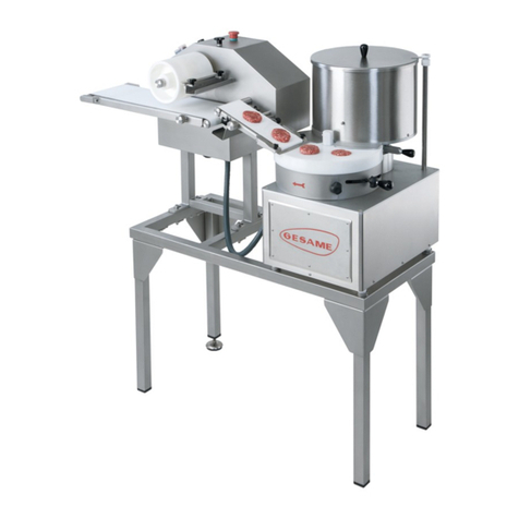
GESAME MH100A User manual

Es imprescindible leer este manual, incluyendo las instrucciones de seguridad, antes de poner en funionamiento la máquina.
You must read this manual and all of the safety instructions before starting the machine.

Este manual contiene información útil e importante, que deberá ser tenida en cuenta, para el uso y mantenimiento de la máquina.
También contiene indicaciones importantes para evitar posibles accidentes o daños mayores y garantizar un buen funcionamiento.
crea oportunas para mejorar la máquina, por exigencias comerciales o constructivas, manteniendo sin embargo, las carac-
terísticas principales descritas en este manual.
Los textos originales de este manual se han realizado con la lengua original del fabricante que es el Español. La traducción al Inglés
se ha realizado partiendo de estos textos originales en Español.
This manual contains useful and important information that
must be considered in the use and maintenance of the machine.
It also contains important instructions to avoid major accidents or damage and to ensure the correct working order of the machine.
in order to
improve the machine or due to commercial or constructive requirements, although the main characteristics described in this manual
shall be maintained.
The original texts in this manual have been written in the manufacturer’s native language, which is Spanish.
The English translation has been produced based on these original texts.
Es imprescindible leer este manual, incluyendo todas las instrucciones de seguridad, antes de poner en funcionamiento la máquina.
Un mal mantenimiento o modificaciones en la máquina pueden ocasionar daños y lesiones importantes al operario.
Datos y especificaciones sujetos a modificaciones sin previo aviso.
You must read this manual and all of the safety instructions before starting the machine. Incorrect maintenance or modifications to the
machine may lead to significant damage or injuries to the operator.
Data and specifications subject to amendment without prior notice.
No será aceptada ninguna responsabilidad en caso de daños debidos a ajustes no autorizados de la máquina y partes eléctricas
realizados por parte del comprador o por uso inadecuado, manejo defectuoso, modificaciones estructurales, supresión de elementos
protectores o de seguridad y uso de repuestos o accesorios que no sean los
El vendedor no se responsabilizará hacia el comprador de los defectos ocasionados por el desgaste natural de la máquina y accesori-
os.
No responsability shall be accepted in the event of damage due to unauthorised adjustments of the machine and electrical parts carried out
by the purchaser or due to undue use, In these cases, the purchaser is responsible for all risks. The vendor
shall not be liable to the purchaser for any defects caused by the natural wear and tear of the machine.

3
4
5
6
7-8
9
3.1 9
9
9
10
10-12
13-14
15
15
16
16
17
17-19
20
6. 21-22
7. 23-27
Información importante para garantizar la seguridad del operario.
Important information to ensure operator safety.
Información importante para garantizar el estado de la máquina.
Important information to ensure the correct working order of the machine.
Información general y consejos.
General information and advice.

4
La dosificadora de hamburguesas automática MH
100A es una máquina muy versátil que permite
dosificar cualquier tipo de forma en función de
los platos que se suministran con ella.
Permite formas redondas desde diámetro 22mm
a diámetro 130mm, forma ovalada y formas
especiales a partir de 10 mm de altura mínima
la porción hasta 28mm la máxima.
Consta de un motorreductor que acciona las
palas de alimentación, una transmisión por
engranajes, para hacer girar el plato dosificador y
unos expulsores de dosificación regulables en
altura que permiten ajustar el peso deseado
La cinta inclinada es un accesorio opcional de la
máquina, que tiene su propio motorreductor. Esta
cinta recoge la hamburguesa que sale del plato
dosificador y la transporta.
Además, la velocidad de giro del plato y la
velocidad de la cinta transportadora son
regulables, mediante un único potenciómetro
situado en el panel de mando.
La máquina también dispone de los siguientes
accesorios: un dispensador de papel y de un
pedal para controlar el funcionamiento.
It allows round shapes ranging from 22 to 130 in
diameter, oval shapes and special shapes with 10
mm minimum portion height and 28 mm
It has a gearmotor that moves the paddles, the
transmission with gears to make the dosing plate rotate,
height-adjustable dosing ejectors to adjust the
desired weight, an optional inclined belt that collects
the shape of the dosing plate. This belt has its own
gearmotor and is fully independent.
Furthermore, the plate’s rotation speed and the
speed of the pulling belts may also be adjusted by
using the two potentiometers located in the main
Capacidad depósito
24 L. / 6,35 Gallons
Peso total (sin accesorios)
85kg
Peso total (con cinta) 95kg
Dimensiones (sin cinta)
44x61x74cm
(width x depth x height)
Dimensiones (con cinta)
74x61x74cm
(width x depth x height)

5
La máquina está equipada con varios dispositivos
de seguridad para la prevención de accidentes.
The machine is fitted with several safety devices
to prevent accidents.
SAFEGUARDS:
1. There is a metal plaque on the moulding
plate (1,Fig.1) to prevent the fingers to be
trapped on the hole. When the conveyor is
assembled, this metal plaque must be
removed, otherwise the conveyor belt will not
work properly.
The plaque can be easily removed unscrewing
the screws (Fig.2).
1. Sobre el plato dosificador se ha colocado una
tapa protectora (1, Fig.1) para evitar que se
puedan introducir los dedos en el pistón.
Cuando se monta la cinta transportadora, esta
tapa protectora debe extraerse de la máquina.
Si no se extrae este tapa, la cinta no funcionará
correctamente.
Mediante un destornillador se extraen los dos
tornillos, y se extrae fácilmente la tapa protectora.
(Fig.2).
Fig.2
Cuando la máquina funciona sin cinta
transportadora siempre tiene que tener montada
la tapa protectora.
Fig.1
1

6
1. The machine is equipped with a transformer-
separator to carry out the entire manoeuvre under
low voltage (24V), a latching contactor and a
rotation variator for the plate and the conveyor
belt with one potentiometer (2,Fig.3). Also is
equipped with a stop-start button (3,Fig.3).
3
2
Fig.4
4
1. La máquina va provista de un transformador-
separador para efectuar toda la maniobra a baja
tensión (24V), un contactor con enclavamiento y
un variador de frecuencia que permite regular la
velocidad de giro del plato y de la banda
transportadora mediante un potenciómetro (2,
Fig.3). También dispone de un pulsador paro-
marcha (3, Fig.3).
2. La tapa superior del depósito lleva incorporado
un imán (4, Fig.4) el cual obliga a tener ésta en
su posición correcta; si no es así, el detector
magnético no detecta el imán, lo cual impide que
la máquina se pueda poner en marcha.
2. The upper cover of the tank is fitted with a
magnet (4, Fig.4) to ensure it remains in the
correct position. Where this is not the case, the
magnetic sensor does not detect the magnet
and the machine cannot be started.
3. En el lateral de la cinta transportadora
inclinada se ha colocado un imán, (5, Fig.5) el
cual también obliga a tener ésta en su posición
correcta; si no es así, el detector magnético no
detecta el imán, lo cual impide que la máquina
se pueda poner en marcha.
4.Todos estos elementos eléctricos que
incorporan la dosificadora automática de
hamburguesas, tras una interrupción del
suministro eléctrico, es necesario presionar el
pulsador de marcha para ponerla de nuevo en
marcha, esto evita el peligro de una puesta en
marcha involuntaria.
3. A magnet has been placed on the side of
the inclined pulling band (5,Fig.5), which also
forces it to be in the correct position. Otherwise,
the magnetic detector does not detect the
magnet, which stops the machine from turning
on.
4. For all of these electrical elements
incorporated into the automatic hamburger
dosing device, after cut-off of electrical supply, it
is necessary to push the start button to start it up
again. This prevents the danger implied by an
involuntary start-up.
Fig.3
Fig.5 5

7
Descargar y transportar la máquina, aún
embalada y colocada sobre el palet, hasta su
emplazamiento final utilizando una transpaleta.
Retirar el embalaje de la máquina, levantando la
caja.
Do not unpack the machine until it is placed in the
working area. Use a forklift to move it around.
Unpack the machine, lifting the box up.
3.2 INSTALACIÓN EN EL LUGAR DE TRABAJO
La máquina debe instalarse sobre una superficie
plana y comprobar que esté bien nivelada.
Que tenga suficiente espacio libre a su alrededor
para poder trabajar sin obstáculos.
Que el nivel de iluminación sea adecuado, de 30
a 60 lux. y cerca de la fuente de alimentación.
Antes de su puesta en marcha, limpiar el interior
de la máquina y las cintas de arrastre con un
trapo húmedo.
The machine must be installed on a table that is
stable and resistant enough to withstand its
weight and any strain placed on it.
There must be enough free space around it in
order to work without obstacles.
The level of lighting must be suitable, from 30 to
60 lux., and close to the power supply.
The machine should be cleaned with a wet cloth
before turning it on.
Asegurarse de que la tensión de red coincida con
la de la máquina suministrada y que aparece
indicada en la placa de características:
La base del enchufe tiene que quedar a una altura
entre 60 y 90 centímetros del suelo y en lugar
visible para el operario, de forma que se pueda
comprobar que la máquina esté desenchufada de
la red cuando se realicen operaciones que
puedan entrañar algún riesgo (limpieza, cambio
de platos, desmontaje…).
La base del enchufe debe tener siempre toma de
tierra (muy importante). No enchufar la máquina
si se observa que el cable de red u otros
elementos se encuentran dañados.
Para su conexión, consultar esquema eléctrico.
Make sure the mains voltage is the same as that
of the supplied machine, as indicated on the
nameplate:
The socket must be at a height of between 60
and 90 centimetres from the ground and in a
visible place for the operator so that he can
ensure the machine is unplugged from the mains
before performing operations that involve some
kind of risk (cleaning, plate changes or
dismantling, etc.).
The socket must always be earthed (very
important).
Do not plug the machine in if the mains cable,
the pedal cable or other components are
damaged.
To plug the machine, refer to Wiring Diagram.

8
En la dosificadora de hamburguesas automática
MH100A identificamos seis elementos para su
utilización:
-depósito
-palas
-plato
-cinta transportadora (opcional)
-dispensador de papel (opcional)
-pedal (opcional)
4.1 SISTEMA DE TRABAJO
Es recomendable hacer estas operaciones
con la máquina parada.
Tirar de la tapa del depósito (1, Fig.6) hacia arriba
para retirarla. Introducir la carne picada en el depósito
(Fig.7)
No hacer funcionar la máquina en seco (sin
carne).
Se recomienda que la carne esté entre 1º y
3ºC y no llenar el depósito hasta arriba; ya
que la masa puede perder consistencia si gira
durante demasiado tiempo: es mejor llenarlo
hasta la mitad e ir rellenándolo de vez en
cuando, utilizando la tolva que se puede
suministrar con la máquina como accesorio
opcional.
Colocar la tapa del depósito, encajando el imán
con el soporte detector magnético.
In the MH Super 114 automatic hamburger
dosing device, we identify six elements to use it:
-tank
-blades
-plate
-belt conveyor (optional)
-paper dispenser (optional)
-switch foot (optional)
4.1 OPERATING SYSTEM
These operaons should be performed with the
machine turned o.
Pull the tank cover (1, Fig.6) upwards to
withdraw it. Place the ground meat in the tank
(Fig.7).
Do not make the machine operate while dry
(without meat).
The meat should be at a temperature of
between 1° and 3 °C and the tank should not
be fully filled, as the mass could lose
consistency if it is allowed to rotate for too
long: it is wiser to half-fill it and top it up
every once in a while using the hopper that
can be supplied with the machine as an
optional accessory.
Replace the tank cover,fitting the magnet onto
the magnetic detector support.
Las palas (2, Fig.7) que se encuentran dentro del
depósito, giran con el fin de presionar la carne
hacia abajo.
The blades (2, Fig.7) locked inside the tank,
rotate in order to push the meat downwards.
1
2
Fig.6
Fig.7

9
Al poner la máquina en marcha el plato va
girando, a la vez que los expulsores bajan, y al
pasar por debajo del depósito se llenan de
carne (1,Fig.8).
Al volver a salir el expulsor, se extraen las
hamburguesas del plato. El operario debe extraer
las hamburguesas del plato de forma manual
mediante una pala.
Si está montada la cinta transportadora
(opcional), las hamburguesas suben
automáticamente por la cinta al salir del plato
(1,Fig.9).
On turning on the machine, the plate rotates while
the extractors lower and, on passing below the tank,
are filled with meat (1,Fig.8).
When the ejector once again exits, it rises with
the beginning of the pulling belt remaining
inclined, which will raise the dosed portion, which
is then deposited on the flat pulling belt to be
ejected or for end finishing before leaving the
pulling belt.
If the inclined belt is assembled (optional), the
patties go directly up the belt (1,Fig.9)
The lever (1, Fig.10) is used to adjust the
weight of the patties, by moving it forward or
backwards.
The position of the conveyor belt in relation to
the forming machine can be adjusted with
several nuts (Fig.11). This must be adjusted in
accordance with the diameter of the patty, so
the transition from the rotating mould to the
conveyor belt is smoother.
1
Fig.10
Fig.9
Con la maneta graduadora (1, Fig.10) podemos
obtener el peso deseado de la hamburguesa,
moviendo hacia delante o hacia atrás.
Moviendo ésta hacia delante conseguiremos
menor peso y si la movemos hacia atrás
conseguiremos más peso.
La posición de la cinta transportadora respecto a
la dosificadora se puede ajustar mediante varios
tornillos (Fig.11). En función del diámetro de las
hamburguesas se debe ajustar la posición de la
cinta. de esta forma se consigue mejorar la
transferencia de las hamburguesas entre el plato
giratorio y la cinta inclinada.
1

10
Mediante dos tornillos superiores (1, Fig.11) se
puede ajustar la inclinación de la cinta. Y
mediante los tornillos inferiores (2,Fig.12) se
ajusta la distancia entre la cinta y el punto de
salida de las hamburguesas en el plato. Se debe
acercar lo máximo posible la cinta al punta de
salida.
Ajustando correctamente los parámetros
anteriores se mejora la transferencia de las
hamburguesas en la entrada de la cinta.
The tilt of the belt can be adjusted with the two
screws (1,Fig.11) located on the top. The
distance of the belt in relation to the machine can
be adjusted with the two screws (2,Fig.12)
located at the bottom.
Correctly adjusting the above parameters
improves the transition of patties between the
mould and the belt.
Fig.11
1
Fig.13
Fig.12
2
Fig.14

11
4.2 ACCESORIOS OPCIONALES
CINTA TRANSPORTADORA
La cinta transportadora es un accesorio opcional
de la dosificadora. Cuando la máquina funciona
sin cinta transportadora, tiene que llevar instalado
el connector ciego sin cables (1, Fig.16).
Mediante dos tuercas grandes hexagonales se
fija la cinta a la estructura de la dosificadora (1,
Fig.17). Al montar la cinta transportadora, se
debe extraer el connector ciego e instalar el
connector con cable de la cinta transportadora.
También se debe extraer la tapa de protección de
los dedos, al colocar la cinta en la máquina.
PEDAL
Como accesorio opcional también está disponible
un pedal para controlar el funcionamiento de la
máquina. SIN pedal la máquina tiene que llevar
colocado un connector ciego sin cable (2,Fig.16).
Cuando se coloca el pedal, debe extraerse el
connector ciego y colocar el connector (1,Fig.18)
proveniente del mismo pedal.
4.2 OPTIONAL ACCESSORIES
BELT CONVEYOR
The conveyor belt is an optional accessory of the
machine. When the forming machine is operating
without the conveyor belt, the blanking plug must
always be connected (1,Fig.16)
The conveyor belt is attached to the structure of
the forming machine with the two hexagonal nuts
(1, Fig.17). When assembling the conveyor belt,
the blanking plug must be extracted and the
conveyor plugged.
The protector plaque on the forming machine
has to be removed when assembling the
conveyor machine.
SWITCH FOOT
The switch foot is available as an additional
accessory. When the machine is operating
without it, a blanking plug is placed (2 Fig 16).
When the switch foot is connected, the blanking
plug must be removed (1,Fig.18) and a switch
plug must be connected.
1
Fig.17
1
1
Fig.16
2
Fig.18

12
DISPENSADOR DE PAPEL
La máquina también puede llevar montado el
dispensador de papel (1,Fig.19) para colocar
papel de diámetro 110mm encima de la
hamburguesa. Este dispensador va fijado al
depósito mediante dos pomos (2,Fig19), se
puede montar y desmontar fácilmente sin el uso
de herramientas.
En el dispensador de papel se activa o desactiva
su funcionamento mediante un posicionador
(3,Fig.19).
El plato que se utiliza cuando se usa el
dispensador de papel es especial, tiene un
mecanizado exclusivo (1,Fig.20) para el
dispensador.
PAPER DISPENSER
The machine has a paper interleaving system (1,
Fig.19) that puts 110mm diameter paper on top of
the patties. This system can be quickly
assembled and disassembled with 2 knobs
(2,Fig.19).
The paper interleave system is activated with the
positioner (3,Fig.19).
The paper interleaving system uses a special
mold with a special insertion (1,Fig.20)
Fig.19
1
Fig.20
1
3
2

13
Desconectar de la red antes de comenzar la
operación de limpieza.
Deben limpiarse después de cada utilización,
todas las partes de la máquina en contacto
con la carne.
Desmontar las partes en contacto con la
carne para efectuar la limpieza. El resto de la
máquina debe limpiarse con un trapo
húmedo, nunca con sistemas de limpieza o
sustancias que puedan dañar la parte
eléctrica.
El limpiador es un rascador (1,Fig.21) situado en
la cinta transportadora.
Una vez se ha terminado la utilización de la
máquina se debe extraer la banda (2,Fig.21) y abrir
el limpiador y proceder a la limpieza de estos dos
elementos. Limpiar con agua y un paño humedo
el rascador, que se queda fijo en la máquina.
Para extraer la banda transportadora se debe
estirar el posicionador y hacer girar el extremo de
plástico según la imagen Fig.21.
Unplug the machine before starting the
cleaning operation.
All parts of the machine that are in
contact with the meat must be cleaned after
each use.
Remove the parts in contact with meat for
cleaning. The rest of the machine shall be
cleaned with a damp cloth, never with
cleaning systems or substances that can
damage the electrical components.
The cleaning system is a scraper located
underneath the conveyor belt. Once the machine
has been used, the belt band bust be removed (2,
Fig.21). Clean it with water and use a wet cloth to
clean the scraper, which is fixed on the machine.
To extract the conveyor band, pull the trigger and
twist the plastic according to the image Fig.21
Fig.21
2
1

14
DESMONTAR Y MONTAR EL DEPOSITO
Para desmontar el depósito se debe extraer
préviamente la tapa del depósito (1,Fig.22). Se
hace girar levemente el depósito (2,Fig.22) y se
estira en dirección vertical, y se extrae
fácilmente.
5.2 DISASSEMBLE AND ASSEMBLE THE
TANK
To disassemble the hopper, first remove the lid
(1, Fig.22). Sightly twist the hopper (2, Fig 22)
and pull it vertically.
5.3 DISASSEMBLE AND ASSEMBLE THE
PADDLES
To disassemble the paddles, first remove the nut
(1, Fig.23), unfasten it with the tool if needed.
Thereafter pull the paddles vertically (2,Fig.23).
Fig.22
1
2
DESMONTAR Y MONTAR LAS PALAS
Para desmontar las palas se debe extraer el
pomo de fijación (1,Fig.23), desenroscándolo con
la herramienta.
Una vez se ha quitado este pomo se estira en
dirección vertical y se extraen las distintas partes
de las palas (2,Fig.23).
Fig.23
1
2

15
5.4 DESMONTAR Y MONTAR EL FONDO
DEPOSITO
Para extraer el fondo del depósito de deben girar
las dos pinzas (1,Fig.24), y luego se estira el
fondo (2,Fig.24) en dirección vertical.
Para el MONTAJE, invertir la secuencia del
desmontaje.
5.5 DESMONTAR Y MONTAR EL PLATO
DOSIFICADOR
Desenroscamos la tuerca (1,Fig.25) con la llave
especial teniendo en cuenta que es de “rosca
izquierda” y extraer el plato (2,Fig.25) hacia
arriba.
El plato dosificador dispone de unos pomos en
su parte inferior, mediante los cuales se pueden
separar las distintas partes del plato y proceder a
una limpieza más profunda de las distintas
partes.
Si la cinta transportadora está montada en la
máquina, se debe abrir el extremo de plástico
(1,Fig.27) de la cinta para que se pueda extraer
el plato. NO es necesario extraer toda la cinta
para desmontar el plato.
To disassemble the hopper base, twist the two
bolts (1, Fig.24), and then pull the base vertically
(2, Fig 24).
To assemble it, repeat the sequence inverse.
5.5 DISASSEMBLE AND ASSEMBLE THE
PLATE
To remove the dispensing plate, first remove the
tank in the manner indicated above.
Loosen the nut (1,Fig.25) using the special
wrench, remembering that it has a “left-hand
thread” and pull the plate out from the top.
(2,Fig.25)
The plate has screws underneath, to break it
apart for a more in-depth cleaning.
If the conveyor belt is assembled, open the
plastic endpoint (1 Fig,27) to remove the plate. It
is NOT necessary to dissemble the conveyor
belt to remove the plate.
Fig.24
21

16
1
Fig.25
3
Con el fin de evitar confusiones, en el
momento de montar, la tuerca del plato de
rosca izquierda es de polietileno BLANCO y la
tuerca de las palas es de ACERO
INOXIDABLE.
Para desmontar los expulsores del plato hay
que abrir los anillos elásticos (1,Fig.28) situados
en la parte inferior del eje del expulsor (2,Fig.28) y
extraerlos junto con la arandela (3,Fig.28) y el
muelle.
En esta operación los expulsores quedan sueltos
pudiendo ya realizarse una perfecta limpieza de
todo el conjunto.
No es recomendable lavar en lavavajillas ya
que las altas temperaturas podrían dañar el
plato y los expulsores. Utilizar sólo agua tibia,
con detergentes neutros.
Hay que tener muy en cuenta en el momento
de montar el plato y las palas, que ambos
llevan una “ranura de arrastre” (Fig.29-
Fig.30), la cual hay que hacer coincidir con el
pasador de arrastre de sus ejes (MUY
IMPORTANTE).
In order to avoid confusion during assembly,
the left-hand thread nut on the plate is
made of WHITE polyethylene and the nut
on the blades is STAINLESS STEEL.
To remove the plate extractor, open the elastic
rings (1,Fig.28) at the bottom of the extractor
shaft (2,Fig.28) and remove them together with
the washer (3,Fig.28) and the springs.
After this operation, the extractors will be left
loose and the entire unit can be correctly cleaned.
Do not wash in a dishwasher, as high
temperatures could damage the plate and the
extractors. Use tepid water only, with neutral
detergents.
Remember, when fitting the plate and the
blades, that both have a “feed groove”(Fig.29-
Fig.30), which must match the feed pin on
their shafts (VERY IMPORTANT).

17
Fig.28
1
Fig.29
23
Fig.30
Fig.27

18
DESMONTAR EL GRADUADOR
Una vez se ha quitado el plato dosificador, se
puede extraer el graduador (1,Fig.31). Se gira el
graduador en sentido horario hasta que se salga
de la máquina.
Una vez desmontado se puede proceder a su
limpieza.
5.6 DISASSEMBLE THE GRADER
Once the mould is off, the adjuster can be
removed (1,Fig.31). Twist the adjuster
anticlockwise until it exits de machine.
Then it is possible to clean the machine.
Fig.31
1

19
6. ESQUEMA ELÉCTRICO
WIRING DIAGRAM
Línia general sobre enchufe monofásico (230VAC)
General line on single-phase plug (230VAC)

20
6. ESQUEMA ELÉCTRICO
WIRING DIAGRAM
Línia general sobre enchufe monofásico (110VAC USA)
General line on single-phase plug (110VAC USA)
Table of contents
Other GESAME Commercial Food Equipment manuals
Popular Commercial Food Equipment manuals by other brands

Silver King
Silver King SKPZ92-EDUS2 Technical manual and replacement parts list

ITV
ITV 110 1P 4B user manual

SERVIT
SERVIT 423FFDS17 user manual

Rational
Rational iVario 2-XS Original installation manual

ROCAM
ROCAM VEGA 60x40 L8 1P+R instruction manual

Apach
Apach BAKERY Line ST A 20 Use and maintenance manual