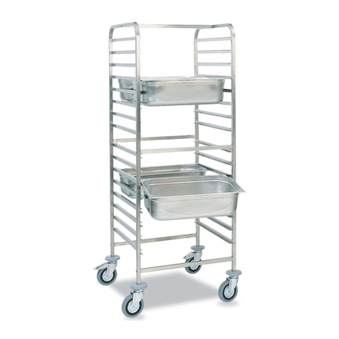
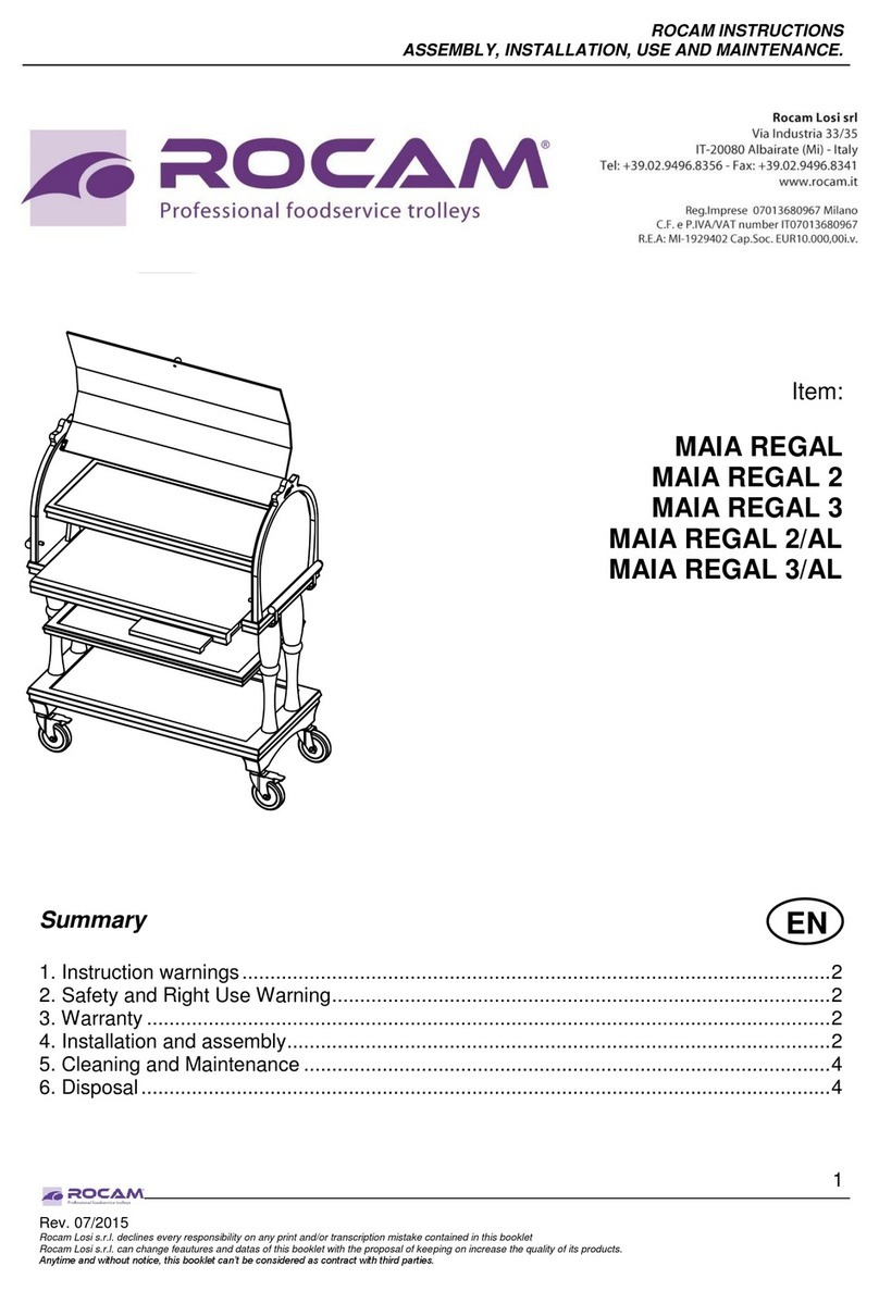
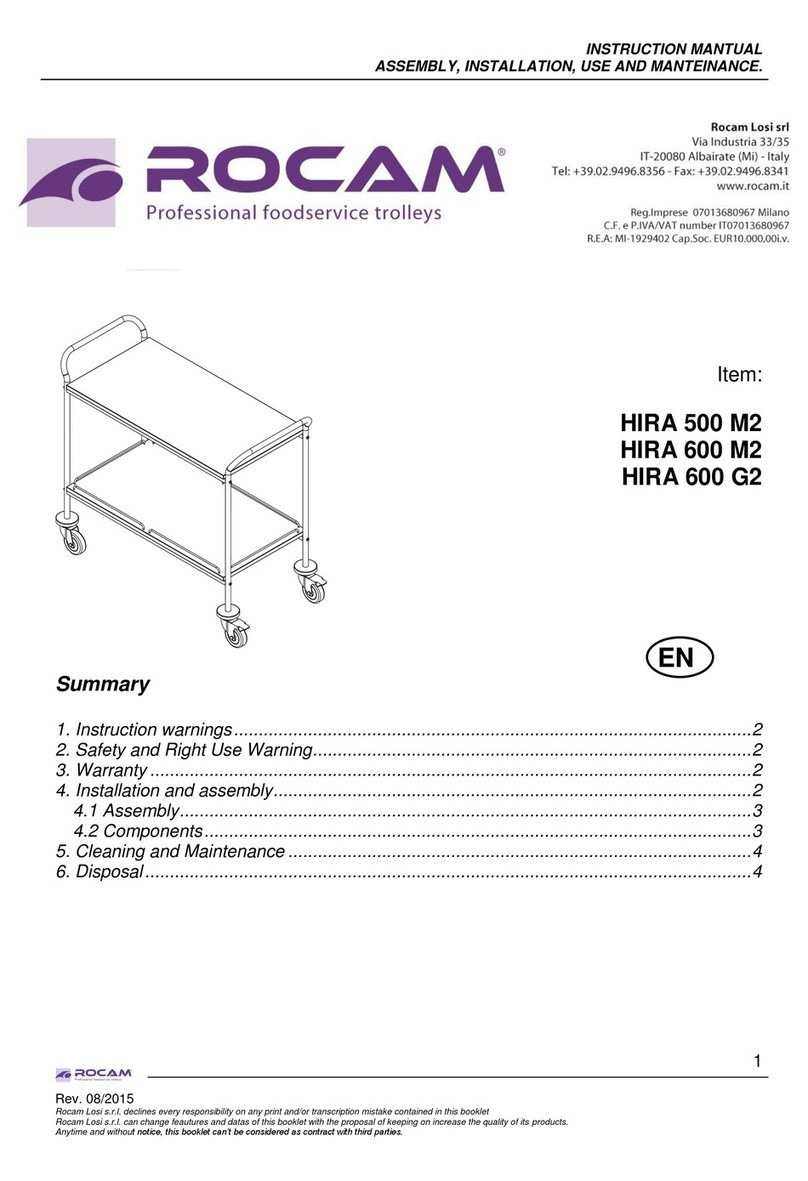
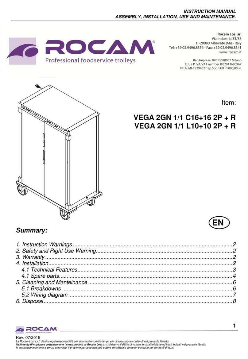
ROCAM VEGA 60x40 L8 1P+R User manual

1
Instruction manual
VEGA 60x40 L8 1P + R
VEGA GN 1/1 C10 1P + R
VEGA GN 1/1 C16 1P + R
VEGA GN 1/1 L10 1P + R
VEGA GN 2/1 C16 1P + R
VEGA GN 2/1 L10 1P + R
VEGA 2GN 1/1 C16+16 2P + R
VEGA 2GN 1/1 L10+10 2P + R
Summary
EN
1. Instruction warnings...............................................................................................................................................2
2. Safety and Right Use Warnings...........................................................................................................................2
3. Warranty.................................................................................................................................................................. 2
3.1 Unpacking.........................................................................................................................................................2
4. Appliance Start Up................................................................................................................................................. 3
5. Technical Features................................................................................................................................................ 3
6. Troubleshooting......................................................................................................................................................3
7. Cleaning and maintenance...................................................................................................................................4
8. Disposal................................................................................................................................................................... 4
9. Spare parts..............................................................................................................................................................4
10. Wiring diagrams................................................................................................................................................... 5

2
1. Instruction warnings
User has to hold the whole instructions. User must store up this document in case of use. The
manufacturer is not responsible of any damage incurred due to the failure of improper use of this manual.
All measures in this manual are in mm.
2. Safety and Right Use Warnings
The Rocam Losi products meet the latest technological evolutions and current safety
guidelines. Trolley line VEGA P, object of this booklet, is designed to be in compliance
with directives and field laws, in order to guarantee a safe and reliable product.
Any other use will be considered inappropriate to the original destination. The producer is
not responsible of any damage caused by an improper use. Responsibility lies only on
user. A proper use also includes compliance with the instructions for use and installation
and any additional documentation as well as the conditions of inspection and maintenance.
3. Warranty
We thank you for purchasing a Rocam Losi product, designed and produced for a professional
environment. Due to commercial and construction requirements, the manufacturer reserves the right to
make changes in order to enhance the quality and use of product. Rocam Losi s.r.l., in compliance with
European Community legislation, grants its products for 12 months. This warranty does not include
electrical parts, labour and all replacements related to an improper use of the good. Any manipulation
carried out automatically excludes the liability of the manufacturer. The products or parts to be replaced
or repaired for unequivocal defects in workmanship and materials used must be in a “free port” at the
offices of the producer, who after a careful inspection, will repair or replace them. The repairs are carried
out exclusively at the headquarters of the manufacturer, and none cost incurred by the customer for
repairs will be refunded by the manufacturer unless explicitly agreed.
ANY MANIPULATION AUTOMATICALLY EXCLUDES THE MANUFACTURER’S LIABILITY AND THE
WARRANTY ON THIS PRODUCT.
3.1 Unpacking
This item is packed and shipped assembled. The manufacturer declines every responsibility for
damages of someone or something caused by the failure to comply with the instructions of this manual.
Do not make any structural change to the trolley.
The elements composing the trolley (plastic, polyurethane foam, bubble wrap, Styrofoam, cardboard and
so on) must be kept away from children as potential sources of danger and must be collected and
disposed off separately in accordance with local regulations.
The manufacturer declines every responsibility of damage of someone or something caused by the
failure to comply with the instructions of this manual.
After the unpacking of the item from its packing, proceed by removing the adhesive plastic tape before
starting up the product. Any residual glue has to be removed carefully (do not use abrasive cleaners).
The device is designed to run on AC to the voltage specified on the technical data plate (located on the
bottom of the tank).
The grounding line is marked by the colours yellow/green and must not be interrupted.
The device is provided with a cable in accordance with the CE regulations and with a schuko plug (that
can be replaced, when necessary, with a different plug, suitable for the specified wattage and in
accordance to the current regulations and guidelines; when necessary, replace the provided cable with a
new one with the same features)
Before switching on the appliance
• Check if the electrical system can withstand the appliance’s load (WATT as indicated on the
technical plate)
• Make sure that the electrical system is provided with ground connection according to the current
norms and guidelines.
• Connect the appliance with the ground network through a cable connected to the specific screw
placed on the external casing of the appliance.
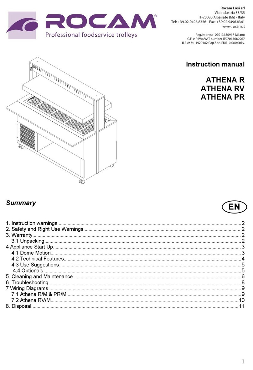
3
4. Appliance Start Up
Once ready to start the appliance, plug the device in
the electrical system and press the red power switch
placed on the upper part of the unit.
As you turn on the appliance the thermostat display will
flash and then it will display “30° C”.
Once started up, the appliance reaches the pre-set
temperature quickly (depending by the starting
temperature, the room temperature and the exposure of
the buffet trolley).
The thermostat is set from the manufacturer on +75°C
for a optimal use of the device. Use the attached
instructions to change the settings of the digital
thermostat.
WARNING: Once the thermostat reaches the max standard temperature (75°C) set
from the manufacturer, the inside temperature will increase up to about 15°C
(according to the situation, to the quantity of product inside the appliance, etc…).
This is not a defect but the result of the double insulated walls effect which retain the
heat for a long time even
FIRST SERVICE WARNINGS:
Some unpleasant smells and smoke could come out the appliance during the first use of the heated appliance
because of the production traces of grease, FOR THE FIRST SERVICE TURN ON THE APPLIANCE (WITH
NOTHING INSIDE) AND LEAVE THE DOOR OPEN FOR SOME MINUTES, in order to eliminate any residual that
could affect the food inside.
WARNING:
Once turned on, the appliance will reach the desired temperature very quickly. In order to avoid any
inconvenience, turn the device on only shortly before starting the service and turn it off shortly after the
end. Do not make any structural change to the appliance.
5. Technical Features
Vega 2GN
1/1 C16+16
2P + R
Vega 2GN
1/1 L10+10
2P + R
Vega GN 2/1
C16 1P + R
Vega GN 2/1
L10 1P + R
Vega GN 1/1
C16 1P + R
Vega GN 1/1
L10 1P + R
Vega GN 1/1
C10 1P + R
Vega 60x40
L8 1P + R
Heating
elements
1700 W +
1700 W
1700 W +
1700 W
1700 W
1700 W
1700 W
1700 W
700 W
700 W
Power
supply
230 V
Temperatu
re Range
+30°/+75°C
Shape
guides
2 x 16 “C”
type
2 x 10 “L”
type
16 x “C”
type
10 x “L”
type
16 x “C”
type
10 x “L”
type
10 x “C”
type
8 x “L” type
Weight
(Kg)
110
110
110
110
95
95
50
55
6. Troubleshooting
Problem
Possible reasons
Solutions
The trolley does
not heat up
Power cut
Check the power presence in the electricity network.
Heating element is burned
Contact the retailer
Thermostat is broken
Contact the retailer
Switch button is broken
Contact the retailer
Power cable is worned-out
Replace the cable with a new one with the same
technical features

4
7. Cleaning and maintenance
WARNING:
Before any cleaning operation unplug the device from the electrical system. Never
wash the appliance with water jets in order to prevent water seepage inside the
electrical components.
Before any cleaning operation wait for the appliance to be cooled down (wait at least
one hour from the end of the service).
The thermic trolley should be cleaned with specific cleansers for stainless steel.The trolley is supplied
with a safety thermostat set to 150°C, which works in case of malfunction of the electronic thermostat. To
reset the system following an interruption due to the safety thermostat, unscrew the top and push the red
button on it.
8. Disposal
At the end of its life cycle, the device must be disposed according to the current regulations
and must, where possible, be disassembled and disposed according to the nature of its
various components. The packing materials (plastic, foam, bubble wrap, styrofoam,
cardboard etc) must be kept away from children as potential sources of danger and must
be collected and disposed separately in accordance with the local regulations.
This marking shown on the product or its literature, indicates that it should not be disposed with other
household wastes at the end of its working life.
To prevent possible harm to the environment or human health from uncontrolled waste disposal, please
separate this from other types of wastes and recycle it responsibly to promote the sustainable reuse of
material resources. Household users should contact either the retailer where they purchased this product,
or their local government office, for details of where and how they can take this item for environmentally
safe recycling.
9. Spare parts
Please find attached assembly and components list at the end of this booklet.

5
10. Wiring diagrams
VEGA 2GN 1/1 C16+16 2P + R - VEGA 2GN 1/1 L10+10 2P + R
Ref.
Description
TS
Safety Thermostat
E-TH
Electronic Thermostat
SON
Probe Electronic Thermostat
RES
Heating Element

6
VEGA GN 1/1 C16 1P + R – VEGA GN 1/1 L10 1P + R
VEGA GN 1/1 C10 1P + R – VEGA 60x40 L8 1P + R
VEGA GN 2/1 C16 1P + R / VEGA GN 2/1 L10 1P + R
Ref.
Description
TS
Safety Thermostat
E-TH
Electronic Thermostat
SON
Probe Electronic Thermostat
RES
Heating Element
This manual suits for next models
7
Table of contents
Other ROCAM Commercial Food Equipment manuals

ROCAM
ROCAM VEGA GN 1/1 C16 User manual

ROCAM
ROCAM MAIA REGAL Quick start guide

ROCAM
ROCAM VEGA 1/1 C8+8 User manual

ROCAM
ROCAM HIRA 500 M2 Quick start guide

ROCAM
ROCAM ATHENA PR User manual

ROCAM
ROCAM ATHENA BM User manual

ROCAM
ROCAM Vega P Series Quick start guide

ROCAM
ROCAM VULCANO 1/1 User manual

ROCAM
ROCAM VULCANO1/1 User manual

ROCAM
ROCAM ATHENA SAL Series User manual