Restmoment RX-3100 Series User manual

Restmoment ALL Digital Conference System
(Restmoment RX-3100 series embedded conference system)
Installation and Operating Manual
V1.1(20150127)

WWW.RESTMOMENT.COM
- 2 -
Contents
PART 1 SAFETY OPERATION..............................................................................................................................- 3 -
1.1 SAFETY OPERATION.......................................................................................................................................................... - 3-
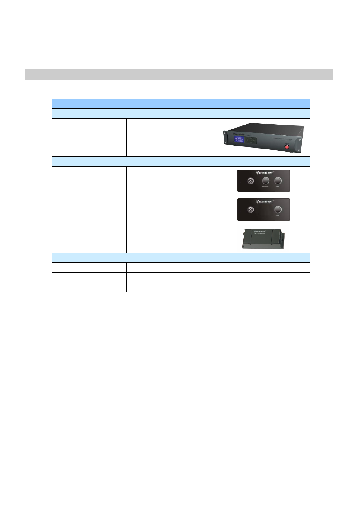
PART 2 SYSTEM COMPONENT......................................................................................................................................- 4 -
2.1 SYSTEM COMPONENT....................................................................................................................................................... - 4-
PART 3 ALL DIGITAL CONFERENCE CONTROLLER...............................................................................................- 5 -
3.1 SYSTEM CONTROLLER RX-M3100................................................................................................................................ - 5-
3.1.1 Function and feature.................................................................................................................................................- 5 -
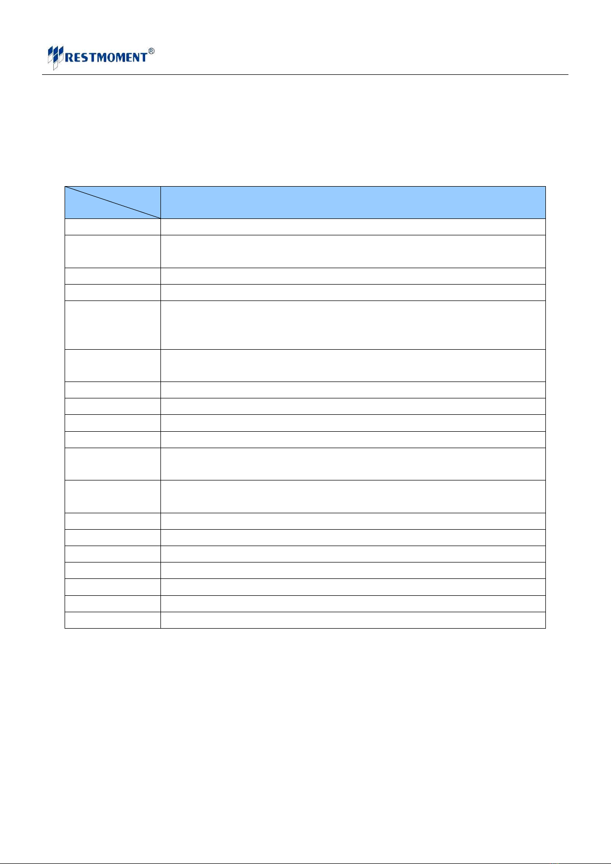
3.1.2 Technical Parameter of conference main controller.................................................................................................- 6 -
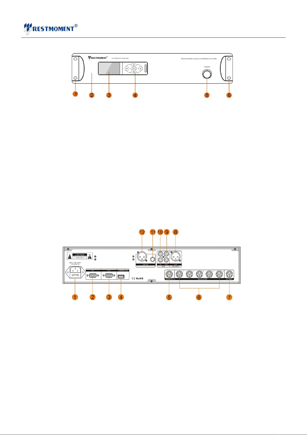
3.1.3 System Ports and Keys..............................................................................................................................................- 6 -
3.2 CONTROLLER ADJUSTMENT.............................................................................................................................................. - 9-
3.2.1 Starting initialization ................................................................................................................................................- 9 -
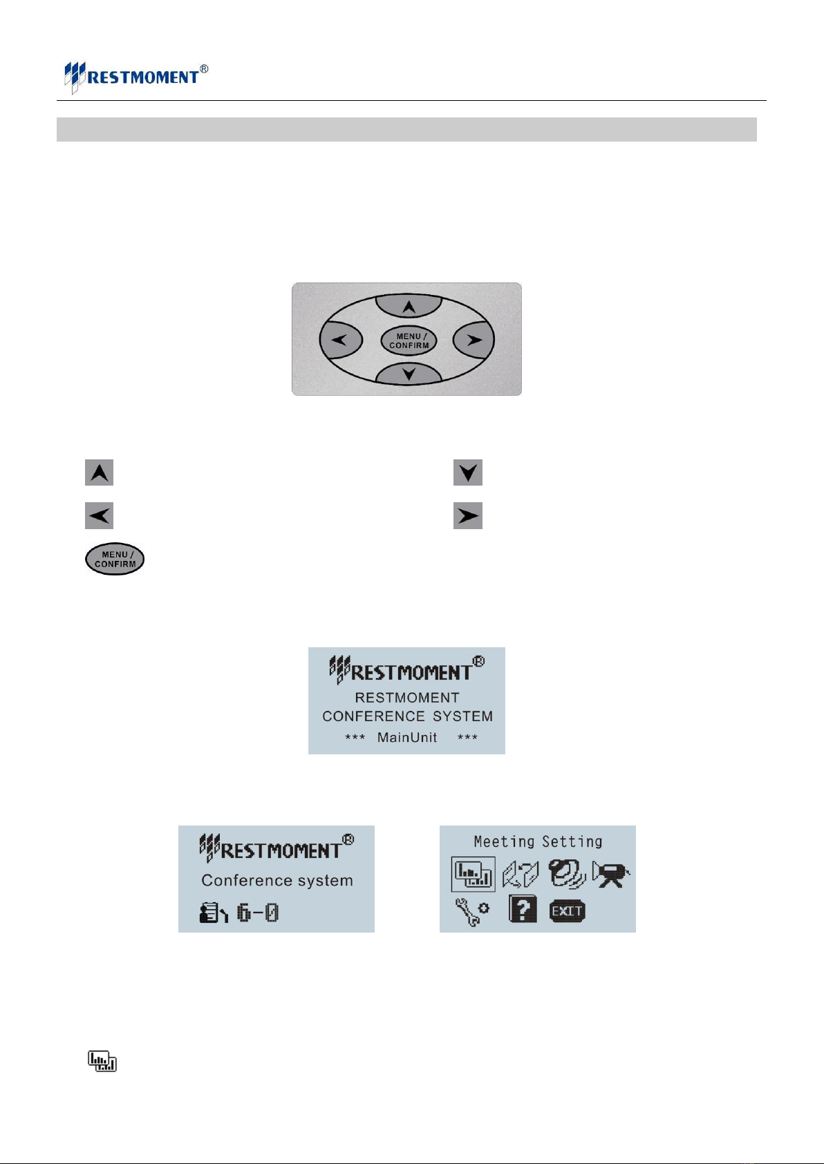
3.2.2 Main menu instruction..............................................................................................................................................- 9 -
3.2.3 New system adjustment step....................................................................................................................................- 10 -
PART 4 EMBEDDED CONFERENCE UNIT.................................................................................................................- 19 -
4.1 SUMMARIZE RX-C/D3100 ............................................................................................................................................. - 19 -
4.1.1 Function and feature...............................................................................................................................................- 19 -
4.1.2 Conference unit technical parameter......................................................................................................................- 20 -
4.1.3 Function key schematic diagram ............................................................................................................................- 20 -
4.1.4 Cable Distributor....................................................................................................................................................- 21 -
PART 5 SYSTEM CONNECTION FIGURE ..................................................................................................................- 22 -
PART 6 FAQ .......................................................................................................................................................................- 24 -

WWW.RESTMOMENT.COM
- 3 -
PART 1 Safety Operation
1.1 Safety Operation
Firstly, thank you very much for using RESTMOMENT conference system. To make sure safety of equipment and
user, please read this safety instruction carefully before installing and using, and operate seriously according
to this manual. Also please keep this safety instruction for future reference. Notices are as below:
1. Wiring during installation must follow national electric safety standards, national fireproofing
regulations and all related local regulations.
2. Protect the power cord from being walked on and do not stack things on the power cord, particularly at
plugs.
3. To make sure earth wire connecting well. Do not use 2- pin plugs. Power supply: 220V 50Hz.
4. Power supply cords:
America, Japan: AC 110 V~120 V 60 Hz
Asia, Europe: AC 220 V~240 V 50 Hz
5. The packaging of equipment is designed for protecting 1.5 meters dropping, but please prevent from stress
and shocking during transportation, installation and storing.
6. Do not place the system equipments on too cold or too hot room.
7. Keep good ventilation to protect the machine.
8. Unplug the system during wet weather or when unused for long periods of time
9. Must unplug the equipment before below operations:
Taking down or resetting any part on machine
Reconnecting any plug in system
10. Do not disassemble or maintain the product by non-authorized personnel to avoid accident or damage. Warning
label is as below:
11. Prevent from any chemicals or liquid.
12. Please check all the connections completely before turning on. Check the set-up of main unit before usage.
13. If you find top warning label on product, it means: Do not open the machine cover to avoid electric shock.
Also please do not place the useless part in the case. Any trouble, please contact with the authorized
personnel.

PART 2 System Component
2.1 System Component
RX-3100 Embedded conference
Main unit
RX-M3100V
Main unit
Embedded unit
RX-C3100
Chairman unit
RX-D3100
Delegate unit
RX-1-4
Cable distribution
Accessories
RX-MBVS
PC software
RX-6P
6 pin cable
RJ-45
5 cat cable

WWW.RESTMOMENT.COM
- 5 -
PART 3 All Digital Conference CONTROLLER
3.1 System Controller RX-M3100
System controller is the core component of ADWCS system. Can control all of the conference
function via the navigation key board of the panel, and LCD display..
Conference controller
3.1.1 Function and feature
Restmoment original conference technique, compliant to IEC60914.
Control all the conference functions by navigation keyboard on front panel
Adopt high speed RISC Embedded hardware structure, more reliable, faster.
Adopt digital audio transmission technique, close to CD sound quality.
2.8 Inch LCD, Chinese and English menu, could order any language.
Built-in input/out volume adjustment.
System can support 150pcs chairman units simultaneously and appoint one as executive chairman.
MIC management modes
Limited mode: 1~6pcs units can be opened simultaneously
FIFO mode: the last opened MIC covers the first opened MIC.
Apply mode: executive chairman can approve or reject the speaking.
Voice activating mode
Free discussion mode: allow all the units to be opened simultaneously
6 channels output ports, which can connect 180pcs units.
Many connecting modes, including “Hand in hand on one line”, “Hand in hand by splitter” and “ Hand in hand in ring
form”
Working with extension controller, the whole system can be extended to 4094pcs units.
Turning off speaking unit, camera will track previous unit. Turning off all the speaking units, it will return to
overall view.
Protocols sharing, it can compatible with all the popular cameras. As the units positions being exchanged,
camera always keep the correct tracking position by edit ID automatically.

WWW.RESTMOMENT.COM
- 6 -
Cooperating with conference management software, the system can have more functions with easier operation.
3.1.2 Technical Parameter of conference main controller
Model
Parameter
All digital conference main controller
Working power
Two models:AC100~120V, 8A / AC220~240V, 4A
Power
consumption
Depends on the quantity of connecting units: Single unit 25W, Maximum 420W
Unit capacity
180pcs units, can be extended to 4096pcs
Audio input
RCA ×2 2V p-p
6.3mm ×1 -50dB
XLR ×1 -50dB
Audio output
RCA ×2 2V p-p
XLR ×1 -50dB
Output impedance
47KΩ
Frequency respond
20~20KHz
SNR
102dB
Dynamic range
106dB
Total harmonic
distortion
< 0.05%
Channel
separation
102dB
Control model
Scalable 8/16/32/64 CH
Connector
RS-232/RS-485
Camera capacity
big 6 pin DIN
Color
Dark grey
Net weight
8KG
Dimension
432×90×350 mm
Installation
Suitable for 19 inch normal stand
3.1.3 System Ports and Keys
Front panel:

WWW.RESTMOMENT.COM
- 7 -
3.2 Front panel
1、Mounting hole for 19 inch stand
2、Front panel of main controller. Aluminum Alloy
3、LCD screen, can adjust the brightness and contrast.
4、5-dimensional direction operation、control key
5、Switch, with electrifying indicator.
6、Mounting hole for 19 inch stand
RX-M3100 Systematic Diagram of Back Panel Ports:
1. Power port: Input AC 100~120V, 8A/AC 220~240V, 4A 50-60Hz power supplier
2. RS232 interface (PC): Computer control system interface.
3. RS232 interface(CCU): Central control system interface.
4、USB interface ( CONTRUL IN): Function extension interface. Reserve for function extension
5、6P DIN interface (INTERPRET IN): interpretation controller digital interface, access to INTERPRET OUT
of the interpretation controller interface.
6、5 PCS 6P DIN digital interfaces ( DELEGATES ): 5 channels conference unit output. Can connect all digital
conference unit equipments in same series.
7、6P DIN digital interface ( EXTEND ): Extension main unit digital interface, connect to EXTEND IN port
of extension main unit.
8、XLR Balance Audio out (BALANCE OUT): Balance Audio out.
9、RCA Audio interface ( LINK OUT ):Audio output interface of System controller, can connect peripheral

WWW.RESTMOMENT.COM
- 8 -
amplifying system or recording system
10、RCA Audio interface ( LINK IN ): Input interface of the third sound source
11、6.3mm MIC input socket
12、Cannon balance interface MIC, connect MIC
RX-M3100V Back panel (Fit with the function of video host):
Back panel
1. Power port: Input AC 100~120V, 8A/AC 220~240V, 4A 50-60Hz power supplier
2. RS232 interface (PC): Computer control system interface.
3. RS232 interface(CCU): Central control system interface.
4、USB interface ( CONTRUL IN): Function extension interface. Reserve for function extension
5、6P DIN interface (INTERPRET IN): interpretation controller digital interface, access to INTERPRET OUT
of the interpretation controller interface.
6、5 PCS 6P DIN digital interfaces ( DRAGOMAN ): 5 channels conference unit output. Can connect all digital
conference unit equipments in same series.
7、6P DIN digital interface ( EXTEND ): Extension main unit digital interface, connect to EXTEND IN port
of extension main unit.
8、Video signal output interface (VIDEO OUT): 8 channels output, connect with television etc outside display
screen.
9、Video signal input interface (VIDEO IN): 8 channels output, connect with camera.
10、XLR Balance Audio out (BALANCE OUT): Balance Audio out.
11、RCA Audio interface ( LINK OUT ):Audio output interface of System controller, can connect peripheral
amplifying system or recording system
12、RCA Audio interface ( LINK IN ): Input interface of the third sound source
13、6.3mm MIC input socket
14、Cannon balance interface MIC, connect MIC
15、RS485 interface: connect with camera, the positive and negative matching
16、2 USB interfaces ( CONTROL OUT ): Function extension interface. Reserve for function extension

WWW.RESTMOMENT.COM
- 9 -
3.2 ControllerAdjustment
When turn on the switch, system controller automatic test and recovery facility.
3.2.1 Starting initialization
1.System controller interface and key operation:
System controller operate interface
Four-dimensional key “up”Four-dimensional key “down”
Four-dimensional key “left”Four-dimensional key “right”
MENU/CONFIRM
2.When open the power, controller will check connection equipment, display equipment list. After editing
ID No, the quantity is the same as equipment list.
controller opening interface
3.if one minute without operation, screen will back to standby interface, as the follow figure
Standby interface main operation interface
3.2.2 Main menu instruction
Conference event: edit conference event and check agenda result.

WWW.RESTMOMENT.COM
- 10 -
Work mode: setup unit work mode.
Speaker set: setup output and input volume.
Video-tracing: setup panorama/unit video tracing.
System setup: unit NO、chairman unit、LED setup、language、IC card and speech count down time.
Help: system version No.
Exit: Exit system menu.
3.2.3 New system adjustment step
3.2.3.1Adjustment steps
1) Check connection as system connection diagram, then turn on system controller. System check units
automatically and show equipment list. Please confirm the equipment list is the same as actually quantity. After
than, system enter standby interface.
Notice: in this list, the chairman unit is executive chairman.
2) Setup unit quantity and ID No.
Press , enter system main unit, select system setup, then select to edit ID No, press
again. Move cursor to “start”key, press at previous.
During this time, the red indicator light on units will flicker. Press “---”on units' display, then the
system can edit ID number for each unit. (From 0001 to total) Finishing it, please press “STOP”on main controller
and return.

WWW.RESTMOMENT.COM
- 11 -
Notice: System need re-edit ID No in below instance
1、Setup new system
2、Move、change、add or delete units
3、There is same ID number for 2 or more units.
4、There is no ID number for unit.
5、ID number is over the total quantity on main controller.
6、System resets. (Return to factory setup)
Notice: We suggest re-edit ID No in below instance
1、Changing the system connection
2、Moving or deleting units
At this moment, we could edit ID No for this unit. Enter “Edit ID No”menu, select right key, and edit
one ID No, as below Figure:
Setup ID No, move cursor to “start”, press . At previous, press unit’s “MIC”key.
3.2.3.2 Vote incontroller
Before vote, should setup units quantity. Vote people quantity should be the same as setup
quantity (for instance, we setup units quantity as 50).
Press , enter system main menu, then enter conference event setup interface, see below Figure
Menu include:
New sign in: setup sign in conference event, enter sign in interface, press “start”, see below Figure:

WWW.RESTMOMENT.COM
- 12 -
New vote: setup vote conference event, enter vote interface, press “start”. More than 10 vote modes
could be selected. see below Figure
New poll: setup poll conference event, enter poll interface, press “start”. Many poll modes could
be selected, for instance, 5 elect 4, see below Figure
Result Display: enter result display interface, could see vote、sign in and poll result. See below
Figure
Result display
Sign in result inquiry

WWW.RESTMOMENT.COM
- 13 -
Vote result inquiry
Poll result inquiry
Meeting Setting: setup count-down time and count rule, see below Figure
Back: back to previous menu
3.2.3.3 Setup work mode in controller
Press enter system main menu and work mode interface, see below Figure:
This menu include:
Limit mote: set the number of delegates permitted to speak at the same time. see below Figure

WWW.RESTMOMENT.COM
- 14 -
FIFO mode: microphone key control with override of the active microphones. see below Figure
Apply mode: microphone key with request –to-speak registration (AUTO). see below Figure
Voice mode: voice-activated microphones with selectable threshold. see below Figure
Notice: Only can choose 1 from 4 modes. Executive chairman and Chairman unit can turn on without limitation
3.2.3.4 Setupvideo trace in controller
Press enter system main menu and volume setup interface, see below Figure:
This menu include:
Camera parameter: setup baud rate、protocol、save No. See below Figure

WWW.RESTMOMENT.COM
- 15 -
Could setup 8 cameras with difference protocol and baud rate.
Operation option: setup scene、save No. See below Figure
Setup scene
1.Unit: 001 option, select scene 0001, press .
Notice: left and right key adjust camera panorama. One camera could have 2 panorama.
2.Move cursor to , adjust camera panorama position.
Notice: “up down、left right”is for camera moving speed.
3.Adjust Focus、Aperture、Zoom、up down、left right.
Notice: “up down、left right”is for camera moving speed.
4.Move cursor to “camera 01”, select correspondence panorama.
Notice: Camera address No will change automatically when adjust panorama position.
5.Move cursor to save NO: 001, select one to save camera position.
6.Move cursor to save “panorama 001”as preset point
Notice: Save No can’t repeat. back to previous menu, RST meat clear all save No.
Setup unit tracing steps: ( see below Figure)
1、Select “unit 0001”, press .
2、Move cursor to , preset unit position
3、“up down、left right”is for camera moving speed.
4、Move cursor to “camera 01”, select correspondence unit.
5、Move cursor to save NO:001, select one to save camera position.
6、Move cursor to save “unit 001”as preset point
Notice: Save No can’t repeat. back to previous menu, RST meat clear all save No.

WWW.RESTMOMENT.COM
- 16 -
Video matrix: setup controller 8 matrix video output. See below Figure
Out put 1-8 meant video output; 1-8 meant 8 cameras.
For instance, setup output 1 with 1-8 cameras video signal, as below steps:
1、Move cursor to “output1”, press , move cursor to 1-8, press , grounding is black.
2、Move cursor to save it.
Turn off video:
As above Figure: preset camera 1 to trace unit No1-5, setup 4 panorama.
“camera 1 corresponding MIC”setup unit 1-5.
3 options
“previous unit”
“No action”
“ID 0001”
“turn off all to panorama”camera switch to panorama when all units are off.
“1~4”meant panorama 1~4. black grounding.
“time”meant camera 1 panorama switch time.
“cameras switch”panorama switch have two types.
“gradation”select panorama gradation according to port.
“dependence”select panorama gradation according to camera No.
For instance:
Port 1 have camera 1、camera 2、camera 3, all cameras have 4 panoramic positions.
“gradation”,panoramic switch gradation: 1a、1b、1c、1d、2a、2b、2c、2d、3a、3b、3c、3d、4a、4b、
4c、4d
“dependence”, panoramic switch gradation: 1a、2a、3a、4a、1b、2b、3b、4b、1c、2c、3c、4c、1d、2d、
3d、4d

WWW.RESTMOMENT.COM
- 17 -
3.2.3.5 Setup volume in controller
Press enter system main menu and volume setup interface, see below Figure:
This menu include
Input volume: could adjust volume as meeting room request.
Output volume: could adjust volume as meeting room request.
3.2.3.6 Setpu system function in controller
Press , enter system main menu, then enter system setup interface, see below Figure
This menu include:
Edit No: setup total human quantity and unit No.
Circuitry checking: Check the quantity of controller and units which connect with system
Notice: Comparing the quantity of checking result with actual units, if data is same, the system connection is normal.
If data is less than actual units, the system connection is in trouble.
Status setup: setup executive chairman unit.
One system only has one executive chairman unit. ID item displays all common chairman unit.
Screen setup: setup LED brightness and contrast. See below Figure:
One system only has one executive chairman unit. ID item displays all common chairman unit.

WWW.RESTMOMENT.COM
- 18 -
MIC setup: Setup “MIC volume”
Other setup: IC card sign-in function, speech count down time. As below Figure:
Central control setup: Baud rate of central control is 9600
Back: back to previous menu.

WWW.RESTMOMENT.COM
- 19 -
PART 4 Embedded conference unit
4.1 Summarize RX-C/D3100
图4.1 Embedded conference unit RX-C/D3100
4.1.1 Function and feature
Restmoment original all digital conference technique, Compliant to IEC60914
All digital audio transmission technique, point to point connection mode, remote transmission won’t
influence sound quality. Distance between two units could reach to 150m.
Embedded design,modern and fashion
Every unit have assigned ID address.
All units are connected by “Hand in hand”
Support “PnP”
Strong anti-interference from mobile phone; Anti-interference from external driving source.
Units have automatic gain function.
5 work modes
Limited mode
Apply mode
Free discussion mode
FIFO mode
Voice activating mode
Chairman unit have Priority, could switch off or mute the speaking units.
Working with camera, Can presetup video trace function.
System support 150 chairman units, could specify one as executive chairman, carry out function as
follow,
Switch work mode Switch off appointed MIC

WWW.RESTMOMENT.COM
- 20 -
Receive or reject application speech
Switch off all MICS
Switch off the earliest MIC
Working with management software to achieve more functions.
4.1.2 Conference unit technical parameter
Mode
Parameter
RX-C/D3100
System capacity
100pcs Depends on system controller,≤65535
Frequency response
30---20KHz
MIC type
Capacitive
MIC sensitivity
-47Db
SNR
90Db
Dynamic range
92Db
Total harmonic
distortion
< 0.05%
Working power
supplier
24DC,-5%
Working current
40mA ±5%
Transmission distance
150M
Maximum
consumption
1W
Control type
RS-485
Connection mode
Hand in Hand
Edit number of units
User-defined
Quantity of chairman
units in a system
150pcs
Quantity of power on
units
1/2/3/4/5/6/or all
Connector
RJ45
Color
Grey, Black, Silver
Installation
Embedded
4.1.3 Function key schematic diagram
Table of contents
Other Restmoment Conference System manuals